EP0314325A1 - Débitmètre à gaz pour usage chimique - Google Patents
Débitmètre à gaz pour usage chimique Download PDFInfo
- Publication number
- EP0314325A1 EP0314325A1 EP88309385A EP88309385A EP0314325A1 EP 0314325 A1 EP0314325 A1 EP 0314325A1 EP 88309385 A EP88309385 A EP 88309385A EP 88309385 A EP88309385 A EP 88309385A EP 0314325 A1 EP0314325 A1 EP 0314325A1
- Authority
- EP
- European Patent Office
- Prior art keywords
- wires
- transmitting
- wire
- flow
- receiving
- Prior art date
- Legal status (The legal status is an assumption and is not a legal conclusion. Google has not performed a legal analysis and makes no representation as to the accuracy of the status listed.)
- Granted
Links
- 238000011144 upstream manufacturing Methods 0.000 claims abstract description 3
- 230000029058 respiratory gaseous exchange Effects 0.000 claims description 5
- 238000000034 method Methods 0.000 claims description 2
- 238000010438 heat treatment Methods 0.000 claims 2
- 238000005259 measurement Methods 0.000 abstract description 2
- 239000007789 gas Substances 0.000 description 14
- 230000000241 respiratory effect Effects 0.000 description 6
- 210000004072 lung Anatomy 0.000 description 4
- 230000004044 response Effects 0.000 description 4
- 230000008859 change Effects 0.000 description 3
- 239000012530 fluid Substances 0.000 description 3
- 238000012806 monitoring device Methods 0.000 description 3
- XLYOFNOQVPJJNP-UHFFFAOYSA-N water Substances O XLYOFNOQVPJJNP-UHFFFAOYSA-N 0.000 description 3
- 230000000977 initiatory effect Effects 0.000 description 2
- 238000012544 monitoring process Methods 0.000 description 2
- 230000036387 respiratory rate Effects 0.000 description 2
- 239000000126 substance Substances 0.000 description 2
- 206010014561 Emphysema Diseases 0.000 description 1
- 101000907549 Takifugu obscurus Flavor peptide Proteins 0.000 description 1
- 208000006673 asthma Diseases 0.000 description 1
- 238000004364 calculation method Methods 0.000 description 1
- 238000010276 construction Methods 0.000 description 1
- 230000001419 dependent effect Effects 0.000 description 1
- 238000013461 design Methods 0.000 description 1
- 238000001514 detection method Methods 0.000 description 1
- 238000010586 diagram Methods 0.000 description 1
- 201000010099 disease Diseases 0.000 description 1
- 208000037265 diseases, disorders, signs and symptoms Diseases 0.000 description 1
- 230000000694 effects Effects 0.000 description 1
- 230000005674 electromagnetic induction Effects 0.000 description 1
- 230000010365 information processing Effects 0.000 description 1
- 229910052751 metal Inorganic materials 0.000 description 1
- 239000002184 metal Substances 0.000 description 1
- 238000012986 modification Methods 0.000 description 1
- 230000004048 modification Effects 0.000 description 1
- 210000003097 mucus Anatomy 0.000 description 1
- 230000008569 process Effects 0.000 description 1
- 230000002035 prolonged effect Effects 0.000 description 1
- 208000023504 respiratory system disease Diseases 0.000 description 1
- 238000012552 review Methods 0.000 description 1
- WFKWXMTUELFFGS-UHFFFAOYSA-N tungsten Chemical compound [W] WFKWXMTUELFFGS-UHFFFAOYSA-N 0.000 description 1
Images

Classifications
-
- A—HUMAN NECESSITIES
- A61—MEDICAL OR VETERINARY SCIENCE; HYGIENE
- A61B—DIAGNOSIS; SURGERY; IDENTIFICATION
- A61B5/00—Measuring for diagnostic purposes; Identification of persons
- A61B5/08—Measuring devices for evaluating the respiratory organs
- A61B5/087—Measuring breath flow
- A61B5/0878—Measuring breath flow using temperature sensing means
-
- G—PHYSICS
- G01—MEASURING; TESTING
- G01F—MEASURING VOLUME, VOLUME FLOW, MASS FLOW OR LIQUID LEVEL; METERING BY VOLUME
- G01F1/00—Measuring the volume flow or mass flow of fluid or fluent solid material wherein the fluid passes through a meter in a continuous flow
- G01F1/704—Measuring the volume flow or mass flow of fluid or fluent solid material wherein the fluid passes through a meter in a continuous flow using marked regions or existing inhomogeneities within the fluid stream, e.g. statistically occurring variations in a fluid parameter
- G01F1/7044—Measuring the volume flow or mass flow of fluid or fluent solid material wherein the fluid passes through a meter in a continuous flow using marked regions or existing inhomogeneities within the fluid stream, e.g. statistically occurring variations in a fluid parameter using thermal tracers
Definitions
- This invention relates to a gas flow meter for clinical use; more particularly, it relates to a pulsed wire fluid flow monitoring device or a tidal volume monitoring device.
- Pneumotachometers or anemometers are instruments that measure the instantaneous flow rate of respired gas. In a clinical environment, they are often used to measure forced expiratory flow, maximum mid-expiratory flow and peak flow rates (see, for example, Plant, D.I., and Webster, J.G., "Ultrasonic measurement of respiratory flow", IEEE Trans. on BME, 27 , 10). Although it is only the flow rate that they may measure directly, absolute volume changes may be obtained by integrating the flow rate.
- the 'flow volume loop' may also be obtained which may be a great help to a physician in obtaining information about the lung and diagnosing diseases, such as emphysema and asthma (see, for example, Plant and Webster, loc cit ; Polo, W.M., "Pneumotachography", Acta Anesth. Scand., Suppl. XI, 171-178; Buss, C., et al , "Design and construction of a pulsed ultrasonic air flowmeter", IEEE Trans. on BME, 33 , 8; Hyatt, R.E., and Black, L.F. , "The flow-volume curve a current perspective", American Review of Respiratory Disease, 107 ).
- diseases such as emphysema and asthma
- Neonates For monitoring Neonates, it is generally accepted that a dynamic range of from 0 to 100 ml/s, a dead space of less than 1.8 ml and a freguency response of 50 Hz or more are adequate. For many applications, it is also necessary to know the direction of flow (i.e. inhalation or exhalation). Some instruments are unable to tell this and they are fitted with one-way valves to differentiate between inhalation and exhalation. There are many different types of pneumotachographs each having certain advantages and disadvantages, the ones most commonly used in clinical environments being Fleisch Pneumotachographs, Wright's Respirometers and Hot wire anemometers.
- Fleisch Pneumotachographs comprise a bundle of narrow tubes placed in the path of the gas flow. As the gas passes through these tubes, a pressure drop, which is linearly related to the flow rate, is developed across them. This pressure drop is measured by a differential pressure transducer calibrated to read out directly in units of flow rate.
- the main disadvantage is in the requirement that the flow must be laminar for the relation between the flow rate and the pressure drop to be linear. Consequently, there are eight different sizes of flow head to accommodate flow rates up to 14 litres/min. Over prolonged use, the sensor becomes clogged with mucus which changes the flow pattern and therefore the accuracy.
- Hot wire anemometry is based on the principle that the passage of cool air over a substance tends to reduce the temperature of that substance by an amount depending on the flow rate (see, for example, Sullivan, et al , loc cit ). Instruments based on this principle usually employ a short tungsten wire heated to a constant temperature well above the temperature of the air in the lungs, say at 50 degrees centigrade. Respiratory air flows over the wire and, at higher flow rates, more electrical energy is needed to keep the wire temperature constant. This energy is not linearly related to the flow rate, but follows a complex relation to, inter alia the ambient temperature, gas viscosity and specific heat capacity. This necessitates complex linearising to counteract the above shortcomings.
- linearisers are usually effective at only one flow rate. Furthermore, these sensors are inherently unidirectional which makes them impractical for measuring tidal volumes. A possible modification to such a sensor is to use one-way valve to add bidirectionality. This is a mechanical device and leads to a reduced frequency response.
- the present invention relates to a pulsed wire fluid monitoring device comprising at least two pulsed wires and at least two sensor wires, the said wires being fixed in the flow of the fluid, means for supplying heat to the pulsed wire, means for detecting and monitoring the heat pulse arriving at the sensor wire, means for measuring the interval between successive pulses, means for measuring the interval between initiating the pulse and detecting the pulse at the sensor wire.
- the present invention is independent of gas composition and ambient temperature, it has no moving parts and hence fast response time, it has a high dynamic range of flow rate, it presents low resistance to the respiratory path and it is very light and compact with low dead space.
- the present invention provides a pulsed hot wire anemometer apparatus characterised in that it comprises two transmitting wires (10,11), and two receiving wires (12,13) in the same plane perpendicular to gas flow, the transmitting wires being on opposite sides of the paired receiving wires and each transmitting wire being upstream of and equally spaced from its receiving wire and both being in a plane parallel to gas flow.
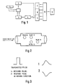
- the sensor head (1) comprises two transmitting wires (10) and (11), one sensor wire (12) and a reference wire (13), receiving wires.
- a pulse of, for example, 75 ⁇ s duration is applied to transmitting wires (10) and (11) by pulse generator (2).
- a cylinder of heat is formed around these wires. It is carried to either left or right depending on the respiratory cycle.
- (10) is the transmitting wire
- (12) is the receiving wire
- (13) is the reference wire.
- Wires (12) and (13) form two arms of a Wheatstone bridge.
- the receiving wire will be hotter than the reference wire (13) (since it is placed directly in front of the transmitting wire) and so its resistance will change by a higher proportion. In the other direction, the roles of the wires are interchanged and so the received pulse is inverted (see accompanying Figure 3).
- the receiving and reference wires are in the same plane perpendicular to the air flow, so the resistance thereof changes by the same amount if the bulk temperature of the gas changes. This makes the bridge output independent of the above parameters.
- a smooth plate is preferably placed between the receiving wires parallel to the direction of the flow so that the receiving wires will be in the boundary layer of the plate where the flow will be more laminar. With this embodiment, the range over which the flow is laminar is increased. There are generally also meshes at either end of the sensor to make the flow pattern inside the sensor independent of the geometry of the connecting tubing, which also produces a more even flow.
- the transmitting wires When the transmitting pulse is initiated, the transmitting wires reach a temperature of about 500 degrees centigrade. In very humid conditions, water condenses on the transmitting wire when the wires are cold (i.e. the pulse is not being sent). As the transmitting pulse is being sent, water droplets tend to explode and take away some part of the metal and eventually cause the breakage of the transmitting wires. Generally, a D.C. current is passed through each transmitting wire to keep its temperature at about 70 degrees centigrade so that no droplets form on the transmitting wire. In addition, the whole sensor is generally heated to about 45 degrees centigrade to prevent water from condensing inside the sensor and changing the flow pattern.
- Two calibration potentiometers are preferably incorporated in the sensor to calibrate the flow rate in either direction.
- the transmitting and the receiving wires have to be very tight to maintain response to high flow rate.
- one end of the wire is preferably fixed to a spring that helps to keep the wire tight.
- the wires may be glued in afterwards to prevent their movement.
- the instrument itself contains a differential amplifier whose output is proportional to the temperature difference between the two receiving wires.
- the output of this amplifier feeds a comparator system.
- the comparator measuring the resistance rise in the sensor wire is set to its reference level just before the resistance rise is expected, since this level is dependent on the temperature of the respired gas and a large temperature difference exists between inspired and respired gases.
- the baseline is sampled by a sample-and-hold circuit and presented to the comparator circuitry, this being an aspect of microcomputer control.
- the comparator continually compares the received signal against this reference level and, if the received pulse is over a certain positive threshold or under a certain negative threshold, the comparator concludes that the pulse has arrived in either positive or negative direction and stops the timer T2 which reflects the time of flight.
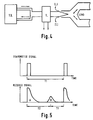
- FIG. 5 depicts graphically the pulsed wire signal and the corresponding detected signals in the sensor wire. Due to electromagnetic induction in the sensor wire from either of the pulsed wires, the received signal is composed of an unwanted induced signal (A) and a signal (B) which results from the pulse of heat arriving at the sensor wire. There are two timing devices, one device (7) measures the actual time (t1) between successive pulses being sent, the second device (6) measures the time (t2) between sending a pulse and the detection of the pulse at the sensor wire. As in accompanying Figure 5, there is a delay time (t3) to allow for a series of calculations, manipulations and display routines which are performed before the next sample may be initiated.
- t3 delay time
- the time between samples (t1) is a variable figure equal to the flight time, where flight time is the time taken for the electrically generated heat pulse to reach the sensor wire i.e. t2, plus an amount of programming time (t3). Therefore, the only accurate way of assessing volume flow is to apply the flow rate (1/t2) obtained in a sample over the time t1 between initiation of successive samples.
- the present instrument may be used to estimate leaks, i.e. the difference between inspiration and expiration volume.
- Leakage may be estimated as follows: The ventilator is set to a low respiration rate of the order of 10 breaths per minute so that the flow rate reaches a steady value during each respiration cycle. If there is no leak, the flow waveform approximates that illustrated in accompanying Figure 6. In the presence of a leak, the flow pattern changes to such as illustrated in accompanying Figure 7. At point C, the pressure inside the lungs and the ventilator are equal and the flow into the lungs drops to zero and Qx is the leakage flow rate during inspiration time. The same applies during expiration, i.e. Qy is the leakage flow rate during expiration (if PFFP is not applied then Qy drops to zero).
- Alveolar tidal volume (alveolar tidal volume 1 + alveolar tidal volume 2) / 2. ADDITIONALLY:
- sample 1 present sample
- sample 2 previous sample
- sample 3 sample before previous sample
Landscapes
- Health & Medical Sciences (AREA)
- Life Sciences & Earth Sciences (AREA)
- Physics & Mathematics (AREA)
- Biomedical Technology (AREA)
- Medical Informatics (AREA)
- Pulmonology (AREA)
- General Physics & Mathematics (AREA)
- Biophysics (AREA)
- Pathology (AREA)
- Engineering & Computer Science (AREA)
- Fluid Mechanics (AREA)
- Heart & Thoracic Surgery (AREA)
- Physiology (AREA)
- Molecular Biology (AREA)
- Surgery (AREA)
- Animal Behavior & Ethology (AREA)
- General Health & Medical Sciences (AREA)
- Public Health (AREA)
- Veterinary Medicine (AREA)
- Measurement Of The Respiration, Hearing Ability, Form, And Blood Characteristics Of Living Organisms (AREA)
- Measuring Volume Flow (AREA)
Applications Claiming Priority (2)
| Application Number | Priority Date | Filing Date | Title |
|---|---|---|---|
| GB878723623A GB8723623D0 (en) | 1987-10-08 | 1987-10-08 | Gas flow meter |
| GB8723623 | 1987-10-08 |
Publications (2)
| Publication Number | Publication Date |
|---|---|
| EP0314325A1 true EP0314325A1 (fr) | 1989-05-03 |
| EP0314325B1 EP0314325B1 (fr) | 1992-03-18 |
Family
ID=10624976
Family Applications (1)
| Application Number | Title | Priority Date | Filing Date |
|---|---|---|---|
| EP19880309385 Expired EP0314325B1 (fr) | 1987-10-08 | 1988-10-07 | Débitmètre à gaz pour usage chimique |
Country Status (4)
| Country | Link |
|---|---|
| EP (1) | EP0314325B1 (fr) |
| JP (1) | JPH01199122A (fr) |
| DE (1) | DE3869321D1 (fr) |
| GB (2) | GB8723623D0 (fr) |
Cited By (9)
| Publication number | Priority date | Publication date | Assignee | Title |
|---|---|---|---|---|
| EP0461281A1 (fr) * | 1990-06-12 | 1991-12-18 | Atochem North America, Inc. | Dispositif pour détécter un écoulement d'air à travers une canalisation |
| WO1992010725A1 (fr) * | 1990-12-11 | 1992-06-25 | Abbey Biosystems Limited | Anemometre a resistance electrique |
| US5201322A (en) * | 1988-08-17 | 1993-04-13 | Elf Atochem North America, Inc. | Device for detecting air flow through a passageway |
| WO1994005204A1 (fr) * | 1992-09-09 | 1994-03-17 | British Technology Group Limited | Debitmetres |
| DE4335332A1 (de) * | 1993-10-18 | 1995-04-20 | Bitop Gmbh | Verfahren und Vorrichtung zur insbesondere nicht invasiven Ermittlung mindestens eines interessierenden Parameters eines Fluid-Rohr-Systems |
| WO1997020500A1 (fr) * | 1995-12-05 | 1997-06-12 | Pulmonary Interface, Inc. | Interface pulmonaire |
| DE102007023840A1 (de) * | 2007-05-21 | 2008-11-27 | Abb Ag | Thermischer Massendurchflussmesser und Verfahren zu dessen Betrieb |
| DE102010054388A1 (de) * | 2010-12-06 | 2011-11-24 | Gebr. Schmidt Fabrik für Feinmechanik GmbH & Co. KG | Verfahren und Auswertegerät zur bidirektionalen Messung von Strömungsgeschwindigkeiten |
| WO2011161060A1 (fr) * | 2010-06-22 | 2011-12-29 | Heinen & Löwenstein Gmbh | Système d'assistance de ventilation, insufflateur, système et procédé pour la ventilation non invasive d'enfants prématurés |
Families Citing this family (4)
| Publication number | Priority date | Publication date | Assignee | Title |
|---|---|---|---|---|
| US5698795A (en) * | 1996-03-29 | 1997-12-16 | Ohmeda Inc. | Thermal time of flight signal guard |
| JP2010131264A (ja) * | 2008-12-05 | 2010-06-17 | Nippon Koden Corp | 呼吸気情報測定センサ |
| DE102009045956A1 (de) * | 2009-10-23 | 2011-04-28 | Endress + Hauser Flowtec Ag | Verfahren zur Erfassung des Durchflusses und thermisches Durchflussmessgerät |
| DE102009045958A1 (de) * | 2009-10-23 | 2011-05-12 | Endress + Hauser Flowtec Ag | Thermisches Durchflussmessgerät |
Citations (5)
| Publication number | Priority date | Publication date | Assignee | Title |
|---|---|---|---|---|
| US3687130A (en) * | 1969-11-26 | 1972-08-29 | Pelam Inc | Instrument to measure pulmonary function |
| US3962917A (en) * | 1974-07-03 | 1976-06-15 | Minato Medical Science Co., Ltd. | Respirometer having thermosensitive elements on both sides of a hot wire |
| US4237730A (en) * | 1978-09-15 | 1980-12-09 | Selas Corporation Of America | Fluid velocity measurement system |
| EP0024327A1 (fr) * | 1979-08-16 | 1981-03-04 | Rico Gesellschaft für Mikroelektronik mbH | Appareil de mesure du debit d'air respiré avec détermination du sens de passage |
| US4483200A (en) * | 1981-01-19 | 1984-11-20 | Anima Corporation | Thermal pulse flowmeter |
-
1987
- 1987-10-08 GB GB878723623A patent/GB8723623D0/en active Pending
-
1988
- 1988-10-07 GB GB8823582A patent/GB2210983A/en not_active Withdrawn
- 1988-10-07 DE DE8888309385T patent/DE3869321D1/de not_active Expired - Lifetime
- 1988-10-07 EP EP19880309385 patent/EP0314325B1/fr not_active Expired
- 1988-10-08 JP JP63254687A patent/JPH01199122A/ja active Pending
Patent Citations (5)
| Publication number | Priority date | Publication date | Assignee | Title |
|---|---|---|---|---|
| US3687130A (en) * | 1969-11-26 | 1972-08-29 | Pelam Inc | Instrument to measure pulmonary function |
| US3962917A (en) * | 1974-07-03 | 1976-06-15 | Minato Medical Science Co., Ltd. | Respirometer having thermosensitive elements on both sides of a hot wire |
| US4237730A (en) * | 1978-09-15 | 1980-12-09 | Selas Corporation Of America | Fluid velocity measurement system |
| EP0024327A1 (fr) * | 1979-08-16 | 1981-03-04 | Rico Gesellschaft für Mikroelektronik mbH | Appareil de mesure du debit d'air respiré avec détermination du sens de passage |
| US4483200A (en) * | 1981-01-19 | 1984-11-20 | Anima Corporation | Thermal pulse flowmeter |
Cited By (12)
| Publication number | Priority date | Publication date | Assignee | Title |
|---|---|---|---|---|
| US5201322A (en) * | 1988-08-17 | 1993-04-13 | Elf Atochem North America, Inc. | Device for detecting air flow through a passageway |
| EP0461281A1 (fr) * | 1990-06-12 | 1991-12-18 | Atochem North America, Inc. | Dispositif pour détécter un écoulement d'air à travers une canalisation |
| WO1992010725A1 (fr) * | 1990-12-11 | 1992-06-25 | Abbey Biosystems Limited | Anemometre a resistance electrique |
| WO1994005204A1 (fr) * | 1992-09-09 | 1994-03-17 | British Technology Group Limited | Debitmetres |
| US5634471A (en) * | 1992-09-09 | 1997-06-03 | British Technology Group Limited | Flowmeters |
| DE4335332A1 (de) * | 1993-10-18 | 1995-04-20 | Bitop Gmbh | Verfahren und Vorrichtung zur insbesondere nicht invasiven Ermittlung mindestens eines interessierenden Parameters eines Fluid-Rohr-Systems |
| WO1997020500A1 (fr) * | 1995-12-05 | 1997-06-12 | Pulmonary Interface, Inc. | Interface pulmonaire |
| DE102007023840A1 (de) * | 2007-05-21 | 2008-11-27 | Abb Ag | Thermischer Massendurchflussmesser und Verfahren zu dessen Betrieb |
| US7644612B2 (en) | 2007-05-21 | 2010-01-12 | Abb Ag | Thermal mass flow meter and method for its operation |
| DE102007023840B4 (de) * | 2007-05-21 | 2012-02-09 | Abb Ag | Thermischer Massendurchflussmesser und Verfahren zu dessen Betrieb |
| WO2011161060A1 (fr) * | 2010-06-22 | 2011-12-29 | Heinen & Löwenstein Gmbh | Système d'assistance de ventilation, insufflateur, système et procédé pour la ventilation non invasive d'enfants prématurés |
| DE102010054388A1 (de) * | 2010-12-06 | 2011-11-24 | Gebr. Schmidt Fabrik für Feinmechanik GmbH & Co. KG | Verfahren und Auswertegerät zur bidirektionalen Messung von Strömungsgeschwindigkeiten |
Also Published As
| Publication number | Publication date |
|---|---|
| DE3869321D1 (de) | 1992-04-23 |
| EP0314325B1 (fr) | 1992-03-18 |
| GB8723623D0 (en) | 1987-11-11 |
| GB8823582D0 (en) | 1988-11-16 |
| GB2210983A (en) | 1989-06-21 |
| JPH01199122A (ja) | 1989-08-10 |
Similar Documents
| Publication | Publication Date | Title |
|---|---|---|
| EP0314325B1 (fr) | Débitmètre à gaz pour usage chimique | |
| US6681643B2 (en) | Method and apparatus for determining a zero gas flow state in a bidirectional gas flow conduit | |
| US5038773A (en) | Flow meter system | |
| Meriläinen et al. | A novel sensor for routine continuous spirometry of intubated patients | |
| EP3243046B1 (fr) | Un débitmètre | |
| US5398695A (en) | Cardiopulmonary performance analyzer having dynamic transit time compensation | |
| Buess et al. | A pulsed diagonal-beam ultrasonic airflow meter | |
| JPS6244223A (ja) | 肺機能を分析する方法及び装置 | |
| JPH02195941A (ja) | 呼吸気流量計 | |
| WO1992010725A1 (fr) | Anemometre a resistance electrique | |
| Mandal | Respirometers including spirometer, pneumotachograph and peak flow meter | |
| JPH0323867B2 (fr) | ||
| US20130345590A1 (en) | Apparatus for quantifying expiratory and inspiratory airflow | |
| US3391569A (en) | Respiration monitor calibrator | |
| Jaffe | Gas flow measurement | |
| JPS6399841A (ja) | 鼻腔通気度計の較正方法 | |
| Elliott et al. | Turbulent airflow meter for long-term monitoring in patient-ventilator circuits | |
| JPS6340967Y2 (fr) | ||
| KR100682026B1 (ko) | 소형 단방향 기류 계측용 호흡관 | |
| West et al. | Measurement of gas volume and gas flow | |
| Roberts | Measurement of volume and flow in gases | |
| Okihara et al. | Integration of flow sensor and optical fiberscope for in-situ breathing and surface image evaluations in small airway | |
| JPH0727941Y2 (ja) | 高頻度人工呼吸器用流量センサ | |
| KR20130052167A (ko) | 병원전 단계 심폐소생술을 위한 호흡기류센서 | |
| Hasegawa et al. | MEMS Flow Sensor Capable of Measuring Multi-Vital Signs of Respiration, Heart Rate, and Body Temperature |
Legal Events
| Date | Code | Title | Description |
|---|---|---|---|
| PUAI | Public reference made under article 153(3) epc to a published international application that has entered the european phase |
Free format text: ORIGINAL CODE: 0009012 |
|
| AK | Designated contracting states |
Kind code of ref document: A1 Designated state(s): DE FR GB IT NL |
|
| 17P | Request for examination filed |
Effective date: 19890808 |
|
| 17Q | First examination report despatched |
Effective date: 19910111 |
|
| GRAA | (expected) grant |
Free format text: ORIGINAL CODE: 0009210 |
|
| AK | Designated contracting states |
Kind code of ref document: B1 Designated state(s): DE FR GB IT NL |
|
| ITF | It: translation for a ep patent filed | ||
| ET | Fr: translation filed | ||
| REF | Corresponds to: |
Ref document number: 3869321 Country of ref document: DE Date of ref document: 19920423 |
|
| RAP2 | Party data changed (patent owner data changed or rights of a patent transferred) |
Owner name: BRITISH TECHNOLOGY GROUP PLC |
|
| RAP4 | Party data changed (patent owner data changed or rights of a patent transferred) |
Owner name: BRITISH TECHNOLOGY GROUP LTD |
|
| NLT2 | Nl: modifications (of names), taken from the european patent patent bulletin |
Owner name: BRITISH TECHNOLOGY GROUP PLC TE LONDEN, GROOT-BRIT |
|
| PGFP | Annual fee paid to national office [announced via postgrant information from national office to epo] |
Ref country code: FR Payment date: 19920929 Year of fee payment: 5 |
|
| PGFP | Annual fee paid to national office [announced via postgrant information from national office to epo] |
Ref country code: DE Payment date: 19921005 Year of fee payment: 5 |
|
| PG25 | Lapsed in a contracting state [announced via postgrant information from national office to epo] |
Ref country code: GB Effective date: 19921007 |
|
| PGFP | Annual fee paid to national office [announced via postgrant information from national office to epo] |
Ref country code: NL Payment date: 19921031 Year of fee payment: 5 |
|
| PLBE | No opposition filed within time limit |
Free format text: ORIGINAL CODE: 0009261 |
|
| STAA | Information on the status of an ep patent application or granted ep patent |
Free format text: STATUS: NO OPPOSITION FILED WITHIN TIME LIMIT |
|
| 26N | No opposition filed | ||
| GBPC | Gb: european patent ceased through non-payment of renewal fee |
Effective date: 19921007 |
|
| PG25 | Lapsed in a contracting state [announced via postgrant information from national office to epo] |
Ref country code: NL Effective date: 19940501 |
|
| NLV4 | Nl: lapsed or anulled due to non-payment of the annual fee | ||
| PG25 | Lapsed in a contracting state [announced via postgrant information from national office to epo] |
Ref country code: FR Effective date: 19940630 |
|
| PG25 | Lapsed in a contracting state [announced via postgrant information from national office to epo] |
Ref country code: DE Effective date: 19940701 |
|
| REG | Reference to a national code |
Ref country code: FR Ref legal event code: ST |
|
| PG25 | Lapsed in a contracting state [announced via postgrant information from national office to epo] |
Ref country code: IT Free format text: LAPSE BECAUSE OF NON-PAYMENT OF DUE FEES;WARNING: LAPSES OF ITALIAN PATENTS WITH EFFECTIVE DATE BEFORE 2007 MAY HAVE OCCURRED AT ANY TIME BEFORE 2007. THE CORRECT EFFECTIVE DATE MAY BE DIFFERENT FROM THE ONE RECORDED. Effective date: 20051007 |