EP0314356A2 - Système de codage par prédiction - Google Patents
Système de codage par prédiction Download PDFInfo
- Publication number
- EP0314356A2 EP0314356A2 EP88309692A EP88309692A EP0314356A2 EP 0314356 A2 EP0314356 A2 EP 0314356A2 EP 88309692 A EP88309692 A EP 88309692A EP 88309692 A EP88309692 A EP 88309692A EP 0314356 A2 EP0314356 A2 EP 0314356A2
- Authority
- EP
- European Patent Office
- Prior art keywords
- time
- input
- data
- predictive
- base expansion
- Prior art date
- Legal status (The legal status is an assumption and is not a legal conclusion. Google has not performed a legal analysis and makes no representation as to the accuracy of the status listed.)
- Granted
Links
Images


Classifications
-
- H—ELECTRICITY
- H04—ELECTRIC COMMUNICATION TECHNIQUE
- H04N—PICTORIAL COMMUNICATION, e.g. TELEVISION
- H04N19/00—Methods or arrangements for coding, decoding, compressing or decompressing digital video signals
- H04N19/50—Methods or arrangements for coding, decoding, compressing or decompressing digital video signals using predictive coding
- H04N19/503—Methods or arrangements for coding, decoding, compressing or decompressing digital video signals using predictive coding involving temporal prediction
- H04N19/51—Motion estimation or motion compensation
- H04N19/577—Motion compensation with bidirectional frame interpolation, i.e. using B-pictures
-
- H—ELECTRICITY
- H04—ELECTRIC COMMUNICATION TECHNIQUE
- H04N—PICTORIAL COMMUNICATION, e.g. TELEVISION
- H04N19/00—Methods or arrangements for coding, decoding, compressing or decompressing digital video signals
- H04N19/42—Methods or arrangements for coding, decoding, compressing or decompressing digital video signals characterised by implementation details or hardware specially adapted for video compression or decompression, e.g. dedicated software implementation
- H04N19/436—Methods or arrangements for coding, decoding, compressing or decompressing digital video signals characterised by implementation details or hardware specially adapted for video compression or decompression, e.g. dedicated software implementation using parallelised computational arrangements
-
- H—ELECTRICITY
- H04—ELECTRIC COMMUNICATION TECHNIQUE
- H04N—PICTORIAL COMMUNICATION, e.g. TELEVISION
- H04N19/00—Methods or arrangements for coding, decoding, compressing or decompressing digital video signals
- H04N19/50—Methods or arrangements for coding, decoding, compressing or decompressing digital video signals using predictive coding
- H04N19/503—Methods or arrangements for coding, decoding, compressing or decompressing digital video signals using predictive coding involving temporal prediction
-
- H—ELECTRICITY
- H04—ELECTRIC COMMUNICATION TECHNIQUE
- H04N—PICTORIAL COMMUNICATION, e.g. TELEVISION
- H04N19/00—Methods or arrangements for coding, decoding, compressing or decompressing digital video signals
- H04N19/30—Methods or arrangements for coding, decoding, compressing or decompressing digital video signals using hierarchical techniques, e.g. scalability
Definitions
- This invention relates to a predictive coding system, and more particularly to a predictive coding system which handles data having a high transmission rate.
- DPCM differential PCM coding
- differential data are non-linearly quantized for the purpose of reducing the amount of data.
- the value of predictive error is large, the difference between the typical value of non-linearly quantized data and the true value becomes large, resulting in deterioration of image data transmitted.
- the predictive coding of an image it is possible to use the so-called two-dimensional predictive coding which uses the correlation in the vertical direction of an image, as well, to further reduce the predictive error.
- an image used for prediction can not be freely selected in the case of performing the aforementioned processing, so that it is impossible to reduce the predictive error.
- the sampling frequency of color signals is generally set lower than the sampling frequency of luminance signals because details of the color attract less of the viewer's attention.
- two DPCM-coding circuits and clock circuits for driving are required, one of each for luminance signals and one of each for color signals.
- a predictive coding system comprising (a) input means for inputting a data sequence sequentially including a number of samples, (b) distribution means for distributing the data sequence input by said input means by making a predetermined time interval including a plurality of samples as a unit to output n-channel data sequences, where n is an integer not smaller than 2, (c) n time-base expansions means for performing time-base expansion of the n-channel data sequences output from said distribution means, and (d) n predictive coding circuits in which the n-channel data sequences which have been time-base expanded by said n time-base expansion means are input, respectively.
- a predictive coding system comprising (a) input means for inputting a data sequence indicating video signals, (b) distribution means for distributing the data sequence input by said input means by making a horizontal scanning line interval as a unit to output n-channel data sequences, where n is an integer not smaller than 2, (c) time-base expansion means for performing time-base expansion of the n-channel data sequences output from said distribution means, respectively, and (d) n predictive coding circuits in which the n-channel data sequences which have been time-base expanded by said n time-base expansion means are input, respectively, said n predictive coding circuits being constituted so as to give and receive data indicating local decoded values each other, and performing predictive coding by utilizing data indicating local decoded values from other predictive coding circuits.
- a predictive coding system comprising (a) input means for inputting a data sequence indicating luminance signals and a data sequence indicating color signals, respectively, (b) distribution means for distributing the data sequence indicating luminance signals input by said input means by making a horizontal scanning line interval as a unit to output n-channel data sequences, where n being an integer not smaller than 2, (c) time-base expansion means for performing time-base expansion of n-channel data sequences output from said distribution means, respectively, and (d) (n+1) predictive coding circuits in which the n-channel data sequences which have been time-base expanded by said n time-base expansion means, respectively, and the data sequence indicating color signals input by said input means are input, respectively.
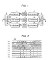
- FIG. 1 is a diagram illustrating a configuration of a coding unit of a system as an embodiment of the present invention
- FIG. 2 is a timing chart for explaining the processing timing of each part in FIG. 1.
- FIG. 1 there is shown a terminal 1 in which a data sequence obtained by sampling television signals is input, and the data input is distributed to three channels by a data distributor 2.
- the data distributor 2 sequentially and cyclically supplies the data input to line momories 3, 4 and 5 for each 1 horizontal scanning line (H).
- FIG. 2 (a) graphically illustrates data being input to the distributor 2, where numerals show horizontal scanning line numbers.
- FIG. 2 (b), (c) and (d) show input data of line momories 3, 4 and 5, respectively, oblique lines showing the absence of data input, and the numerals being horizontal scanning line numbers.
- the line memories 3, 4 and 5 are for expanding the time bases of input data by three times and for outputting the resultant data, respectively, and take in data of 1H interval, and perform data read-out during a period of 3H interval of the input data.
- the data output timings of the line momories 3, 4 and 5 are, as shown in FIG. 2 (3), (f) and (g), set so that data of 3H interval are similtaneously output in parallel.
- the transmission rate of data read from the line memories 3, 4 and 5 becomes 1/3 of the transmission rate of data input, and these data are input to DPCM coders 6, 7 and 8 in parallel.
- the DPCM coders 6, 7 and 8 perform a well-known processing, and supply differential data to line memories 11, 12 and 13 in parallel.
- the line memories 11, 12 and 13 take in differential data, perform time compression to 1/3 in a unit of 1H interval and output the resultant data.
- the read-out timings for these operations are set so that each memory 11, 12 and 13 sequentially outputs data of 1H interval for each 1H period of the input data.
- the differential data read out from the line memories 11, 12 and 13 are subjected to time-base multiplexing in a data multiplexing circuit 14, are line-sequentially output with a timing shown in FIG. 2 (h) like the original input data, and are sent out to various transmission lines via a terminal 15.
- the transmission rate of data input to each DPCM coder, 6 7 and 8 becomes 1/3 of the input data, and on the whole DPCM coding can be performed with a speed three times the respective processing speed of the DPCM coders 6, 7 and 8.
- data of the total picture elements with regard to each horizontal scanning line are sequentially input to each DPCM coder, so that a coding utilizing a correlation between adjacent picture elements can be performed, and thus the predictive error does not become large when a predictive value is produced.
- FIG. 3 is a diagram illustrating a configuration of a decoding unit corresponding to the coding unit in FIG. 1, wherein differential data are line-sequentially input to a terminal 21 via a transmission line.
- a data distributor 22 sequentially and cyclically supplies these differential data for every 1H interval thereof to line memories 23, 24 and 25.
- the line memories 23, 24 and 25 have a configuration to perform the time-base expansion of differential data of 1H interval input during a period of 1H interval of the input differential data in a unit of 1H interval to three times, respectively, and to output the resultant data. They output the data simultaneously like the line memories 3, 4 and 5.
- DPCM decoders 26, 27 and 28 receive the outputs from the line memories 23, 24 and 25, perform DPCM decoding, and supply the decoded data to line memories 31, 32 and 33.
- the line memories 31, 32 and 33 perform the time-base compression of decoded data of 1H interval input during a period of 3H interval of the input differential data in a unit of 1H interval to 1/3.
- the line memories 31, 32 and 33 sequentially output the decoded data of 1H interval to input in a data multiplexing circuit 34, and these data are line-seqientially multiplexed again to be output from a terminal 35.
- decoding can be performed with a speed three times the processing speed of each DPCM decoder.
- FIGS. 4 and 5 are diagrams illustrating a concrete example of the DPCM coders 6, 7 and 8 in FIG. 1, respectively.
- FIG. 4 there are shown a terminal 41 to which PCM data are to be input, an arithmetic unit 42 which outputs a differential value between a predictive value and an input value, a quantizer 43 which non-linearly quantizes the output of the arithmetic unit 42 with a quantizing characteristic Q to reduce bit numbers, and data from the non-linear quantizer 43 are output from a terminal 48 as the output from this coder.
- a circuit 44 for setting the typical value for the output value of the quantizer 43 has a characteris tic Q ⁇ 1 inverse to the quantizing characteristic Q
- an adder 45 is for adding the aforementioned typical value and the predictive value of the preceding picture element to obtain the local decoded value.
- a coefficient multiplier 46 which multiplies the predictive coefficient P is delayed by a period of one picture element interval by a delay circuit 47 to be used as a new predictive value, and is supplied to the arithmetic unit 42 and the adder 45.
- This adder itself is well known, so that detailed explanation of the operation thereof will be omitted.
- the adder in FIG. 4 produces the predictive value by using only an adjacent picture element in the same horizontal scanning line as the picture element in question.
- the system according to the present invention is not only applicable to such a system using a coder which performs the so-called preceding value prediction, but also is applicable to a system using a coder which uses even the correlation of an image in the temporal direction: one example of this kind of coder is shown in FIG. 5.
- FIG. 5 like components to those in FIG. 4 are indicated by like numerals, and explanation thereof will be omitted.
- the local decoded value obtained by the adder 45 is multiplied with the predictive coefficient in the coefficient multiplier 46, and then is input to the delay circuit 47 for one picture element interval and to a delay circuit 51 for one frame interval.
- the outputs of these delay circuits 47 and 51 are multiplied with the coefficient in coefficient multipliers 52 and 53, and then are added in an adder 54 to obtain the predictive value.
- Coefficients (k) and (1-k) of the coefficient multipliers 52 and 53 are determined in a movement detection circuit 55 which detects the amount of the correlation of the image in the temporal direction. That is, the larger the correlation in the temporal direction, the smaller becomes the value of k.
- a movement detection circuit 55 which detects the amount of the correlation of the image in the temporal direction. That is, the larger the correlation in the temporal direction, the smaller becomes the value of k.
- video signals have been presumed as data to be handled, it is not limited thereto and the present invention can be applied even to the case in which other information signals are handled.
- a unit for time-base conversion has been taken as 1H interval, taking in consideration the fact that an initializing timing of the DPCM coder, i.e., a timing which sends data not differentiated will exist at least with a timing of the start of each horizontal scanning line.
- the initializing cycle may be made as a unit for time-base conversion.
- n ( ⁇ 2)-channel parallel processing it is possible in general to perform n ( ⁇ 2)-channel parallel processing. It is needless to say that in this case a time-base expansion circuit for expanding n times is provided in the front stage of n coders, and a time-base compression circuit for compressing to 1/n is provided in the rear stage.
- FIGS. 6 (A), (B) and (C) are diagrams for explaining a system of an embodiment of the present invention.
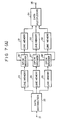
- FIG. 6 (A) is a diagram illustrating a schematic configuration of a coding unit of a system as the present embodiment, in which like components as in FIG. 1 are indicated by like numerals, and detailed explanation thereof will be omitted.
- DPCM coders 6′, 7′ and 8′ perform two-dimensional prediction by using data from other coders 8′, 6′ and 7′, and supply differential data to line memories 11, 12 and 13 in parallel.
- FIG. 6 (B) is a diagram illustrating concrete configurations of the two-dimensional DPCM coders 6′, 7′ and 8′ in FIG. 6 (A), and FIG. 6 (C) is a diagram for explaining the method for operating of predictive values by the coders in FIG. 6 (B).
- a circuit within the two-dimensional DPCM coder 6′ will be explained.
- a terminal 100 in which data read out from the line memory 6 are input.
- An arithmetic unit 101 is for operating the differential value between the predictive value and the input value, and a quantizer 102 non-linearly quantizes the output of the arithmetic unit 101 with a quantizing character Q to reduce bit numbers, and data which the non-linear quantizer 102 outputs are supplied to a delay circuit 113 and to a circuit 103.
- the circuit 103 for setting the typical value for the output value of the quantizer 102 has a characteristic Q ⁇ 1 inverse to the quantizing characteristic Q, and an adder 104 is for adding the aforementioned typical value and the predictive value of the preceding picture element to obtain the local decoded value.
- the output of a predictive unit 105 is supplied to the arithmetic unit 101 and the adder 104 as the predictive value.
- the above-described components 101-105 in the coder 6′ are the same as the components 122-126 and 132-136 in the coders 7′ and 8′, respectively, and the configuration is the same as for predictive units 105, 126 and 136 of each coder 6, 7 and 8.
- explanation will be made by taking the predictive unit 105 as an example.
- a delay unit 106 is for delaying the local decoded value obtained from the adder 104 by a period of 1 picture element interval (D).
- the output of said delay unit 106 is the local decoded value of the picture element right before that, i.e., the adjacent picture element in the horizontal direction (shown as C in FIG. 6 (C)).
- a delay unit 112 is for delaying the local decoded value output from an adder 135 of the coder 8 by a period shorter than 3 horizontal scanning periods by an amount equal to the interval of 6 picture elements ( 3H - 6D ).
- 3 horizontal scanning period means 3 horizontal scanning period of the input signals to the terminal 1 in FIG. 1 (A), which corresponds to a period wherein the image data of 1H interval are input to the coders 6, 7 and 8, respectively.
- the coder 8 there is provided a delay unit for a period of 4 times the interval of a picture element in the input side.
- the local decoded value of the picture element shown as A in FIG. 6 (C)
- the output of a delay unit 109 for 1D is the local decoded value of the picture element (shown as B in FIG. 6 (C)) in the preced ing line at the same location in the horizontal direction.
- the coefficients a, b and c of the local decoded values of the picture elements A, B and C are multiplied by coefficient multipliers 108, 110 and 107, added by an adder 111 to obtain the predictive value of the picture element S. That is, in order to operate the predictive value of the picture element S in FIG. 6 (C), the local decoded values of 3 picture elements shown by O in the figure are used.
- Data input are delayed by 1D by a delay unit 121 in the coder 7, so that if it is assumed that the predictive value obtained from the predictive unit 126 evaluates the predicttive value with regard to the picture element S in FIG. 6 (C), the local decoded value output from the coder 6 to the coder 7 becomes the one with regard to the picture element A.
- data input are delayed by 2D by a delay unit 131 in the coder 8, so that if it is assumed that the predictive value obtained from the predictive unit 136 is with regard to the picture element S in FIG. 1 (C), the local decoded value output from the coder 7 to the coder 8 becomes the one with regard to the picture element A.
- delay units 113 and 127 have delay periods of 4D and 2D, respectively, and are provided so that the outputs of the coders 6, 7 and 8 have the same timing with regard to picture elements aligning in the vertical direction.
- the transmission rates of data input in each DPCM coder 6, 7 and 8 become 1/3 of that of the input data, and on the whole DPCM coding can be performed with a speed three times the processing speed of each of the DPCM coders 6, 7 and 8. Since data of total picture elements with regard to each horizontal scanning line are sequentially input in each DPCM coder, a coding utilizing a correlation between adjacent picture elements can be performed, and thus predictive error does not become large when a predictive value is produced. Further, in the line right before, picture elements located in front and in rear in the horizontal direction can be utilized, so that a two-dimensional prediction with a high predictive accuracy becomes possible.
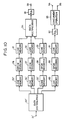
- FIG. 7 (A) is a diagram illustrating a schematic configuration of a decoding unit corresponding to the coding unit in FIG. 6.
- DPCM decoders 26′, 27′ and 28′ receive the outputs of the line memories 23, 24 and 15 and decoded values of other decoders to perform DPCM decoding, and supply the decoded data to line memories 31, 32 and 33.
- FIG. 7 (B) is a diagram illustrating concrete configurational examples of the decoders 26′, 27′ and 28′ which correspond to the decoders 6′, 7′ and 8′ illustrated in FIG. 6 (B).
- delay units 211 and 221 for 2D and 4D for shifting the decoding timings of picture elements aligning in the vertical direction of a picture
- typical value-setting circuits 201, 212 and 213 the same as 103 respectively, adders, 202, 213 and 223 for outputting decoded values
- arithmetic units 205, 216 and 225 for performing the same operations as the predictive unit 105
- a delay unit 206 for supplying decoded values of scanning lines decoding-processed in the decoder 28 during a period right before (3H - 6D)
- delay units 203 and 214 for 4D and 2D for making coincide the output timings of the decoded values of picture elements aligning in the vertical direction of a picture.
- decoding can be performed with a speed three times the processing speed of each DPCM decoder.
- the processing time T of data from the outputs of the predictive units 105, 126 and 136 to the inputs have been neglected, but it can not be neglected when it is intended to realize a higher speed of the processing. If this time T is taken into consideration, the delay time of the delay unit 106 should be made as (D - T). That is, it is necessary to precede the processing timing of the coder which generates the local decoded value used in the operation of the predictive value to the processing timing of the coder which operates this predictive value by T.
- the configuration of a two-dimensional predictive unit is not limited to the configuration of the above-described embodiment. However, it is necessary to design by taking into consideration the existance of the aforementioned period T.
- FIG. 8 is a diagram illustrating a configuration of a coding unit of a system as further another embodiment of the present invention
- FIG. 9 is a timing chart for explain ing the processing timing of each unit in FIG. 8.
- a terminal 10 in which luminance signals are to be input, and an analog-digital (A/D) converter 9 which performs sampling of the luminance signals input with a predetermined frequency F s to make digital data of several bits.
- the data sequence which the A/D converter 9 outputs is supplied to the data distributor 2, and to the DPCM coders 6, 7 and 8 via the line memories 3, 4 and 5 to be coded like in FIG. 1, and is supplied to line memories 11′, 12′ and 13′.
- FIG. 1 is a diagram illustrating a configuration of a coding unit of a system as further another embodiment of the present invention
- FIG. 9 is a timing chart for explain ing the processing timing of each unit in FIG. 8.
- FIG. 8 there are shown a terminal 10 in which luminance signals are to be
- FIG. 9 (a) graphically illustrates data being input in the distributor 2, where Y indicates the luminous signal and numerals indicate horizontal scanning line numbers.
- FIG. 9 (c), (d) and (e) indicate input data in the line memories 3, 4 and 5, respectively, and oblique lines indicate the absence of data input.
- the data output timings of the line memories 3, 4 and 5 are, as shown in FIG. 9 (f), (g) and (h), set so that data for 3H interval are simultaneously output in parallel.
- This output timing of the A/D converter 79 is graphically illustrated in FIG. 9 (b).
- C indicates color signals. Accordingly, when C1 is C N , then C3, C5 and C7 are also C N , and C2, C4, C6 and C8 are C W .
- a line memory 80 delays the output of the A/D converter 79 by a period of 3H, and outputs with a timing shown in FIG. 9 (i).
- the capacity of the line memory 80 is the same as the capacity of the line memories 3, 4 and 5, but the line memory 80 can delay by a period of 3H since the sampling number per unit time of the line-sequential color signals is 1/3 of the sampling number of the luminance signals.
- a DPCM coder 81 in which the output data of the line memory 80 are to be input is capable of having totally the same configuration as the DPCM coders 6, 7 and 8, and at the same time common clocks can be used for the driving thereof.
- the output data of the DPCM coder 81 are supplied to a line memory 82 with a timing illustrated in FIG. 9 (i), and the line memory 82 takes in a portion of 3H interval thereof, performs time-base compression, and outputs with a timing illustrated in FIG. 9 (k). That is, it outputs by 1H interval at a time during the last 1/4H period of each 1H period.
- the line memories 11′, 12′ and 13′ output by 1H interval during the first 3/4 period of each 1H period ( shown in FIG.
- a data multiplexing circuit 14′ performs multiplexing of these output data of the line memories 11′, 12′, 13′ and 82, and send outs from a terminal 15′ to various transmission lines with a timing illustrated in FIG. 9 (l).
- the DPCM coders 6, 7, 8 and 81 can have the totally same configuration, so that it is not necessary to prepare separate coders for luminance signals and for color signals, and thus it is possible to realize circuits with a lower cost.
- the circuit configuraion can be simplified because each DPCM coder 6, 7, 8 and 81 can be operated with a common clock.
- FIG. 10 is a diagram illustrating a configuration of a decoding unit corresponding to the coding unit in FIG. 8, wherein data sent out from the coder in FIG. 8 are input in a terminal 21′ via a transmission line.
- a data distributor 22′ supplies these data to line memories 23′, 24′, 25′ and 89 for every 1H interval with time sharing.
- the line memories 23′, 24′ and 25′ have a configuration wherein dif ferential data of 1H interval input during a period of 3/4H interval of the input differential data are performed time-base expansion thereof in a unit of 1H interval, respectively, and the resultant data are output in a period of 3H interval, and the line memories 3, 4 and 5 are arranged to simultaneously output the same data in the same way.
- the DPCM decoders 26, 27 and 28 receive the outputs of the line memories 23, 24 and 25, perform DPCM decoding of luminance signals, and supply the decoded data to line memories 31, 32 and 33.
- the line memories 31, 32 and 33 perform time-base compression to 1/3 the decoded data of 1H interval input during a period of 3H interval of the input differential data in a unit of 1H interval, respectively.
- the line memories 31, 32 and 33 sequentially output the decoded data of 1H interval to input in a data multiplexing circuit 34, and these data are line-sequentially multiplexed again, are input in a D/A converter 38 to be made as analog data, and are output from a terminal 39 as luminance signals.
- differential data with regard to line-sequential color signals are output by 1H interval for every 1H period during a period of 1 ⁇ 4H interval, and the line memory 89 performs time-base expansion of these data to 4 times in a unit of 1H interval and inputs to a DPCM decoder 90.
- the data decoded by the DPCM decoder 90 are delayed by a period of 3H by a line memory 91, and then are supplied to a D/A converter 92 to be restored to analog line-sequential color-difference signals.
- the line-sequential color-difference signals output form the D/A converter 92 are subjected to the concurrent operation of a well-known concurrent operation circuit 93 by performing line interpolation in the vertical direction of a picture with regard to C N and C W , and are output from terminals 94 and 95 as two kinds of color difference signals.
- luminance signals can be processed with a speed three times the processing speed of each DPCM decoder, and at the same time each decoder 26, 27, 28 and 90 can have totally the same configuration. Further, these decoders can be operated with the same clock.
Landscapes
- Engineering & Computer Science (AREA)
- Multimedia (AREA)
- Signal Processing (AREA)
- Computing Systems (AREA)
- Theoretical Computer Science (AREA)
- Compression Or Coding Systems Of Tv Signals (AREA)
- Color Television Systems (AREA)
- Compression, Expansion, Code Conversion, And Decoders (AREA)
Applications Claiming Priority (6)
| Application Number | Priority Date | Filing Date | Title |
|---|---|---|---|
| JP272282/87 | 1987-10-27 | ||
| JP62272282A JPH01114181A (ja) | 1987-10-27 | 1987-10-27 | 符号化システム |
| JP62276346A JPH01119185A (ja) | 1987-10-31 | 1987-10-31 | 予測符号化装置 |
| JP276346/87 | 1987-10-31 | ||
| JP27634787A JP2603274B2 (ja) | 1987-10-31 | 1987-10-31 | 符号化装置 |
| JP276347/87 | 1987-10-31 |
Publications (3)
| Publication Number | Publication Date |
|---|---|
| EP0314356A2 true EP0314356A2 (fr) | 1989-05-03 |
| EP0314356A3 EP0314356A3 (fr) | 1990-08-16 |
| EP0314356B1 EP0314356B1 (fr) | 1999-03-31 |
Family
ID=27335990
Family Applications (1)
| Application Number | Title | Priority Date | Filing Date |
|---|---|---|---|
| EP88309692A Expired - Lifetime EP0314356B1 (fr) | 1987-10-27 | 1988-10-17 | Système de codage par prédiction |
Country Status (3)
| Country | Link |
|---|---|
| US (1) | US5103294A (fr) |
| EP (1) | EP0314356B1 (fr) |
| DE (1) | DE3856318T2 (fr) |
Cited By (6)
| Publication number | Priority date | Publication date | Assignee | Title |
|---|---|---|---|---|
| WO1991010314A1 (fr) * | 1989-12-22 | 1991-07-11 | Eastman Kodak Company | Compression a haute vitesse de donnees d'imagerie |
| EP0442548A1 (fr) * | 1990-01-30 | 1991-08-21 | Laboratoires D'electronique Philips S.A.S. | Dispositifs de codage et de décodage à longueur variable de signaux numériques |
| FR2662318A1 (fr) * | 1990-05-15 | 1991-11-22 | Philips Electronique Lab | Dispositif de decodage a longueur variable de signaux numeriques. |
| EP0398328A3 (fr) * | 1989-05-18 | 1993-01-13 | Nec Corporation | Dispositif de codage pour le codage et le décodage d'un signal d'image à vitesse élevée |
| EP0588410A1 (fr) * | 1992-09-14 | 1994-03-23 | Koninklijke KPN N.V. | Système comprenant un premier codeur pour coder un premier signal digital et un second codeur pour coder un second signal digital (e.g. un signal vidéo stéréoscopique) |
| WO2002065785A3 (fr) * | 2001-02-13 | 2003-03-27 | Quvis Inc | Systeme dilatable de traitement d'images animees |
Families Citing this family (4)
| Publication number | Priority date | Publication date | Assignee | Title |
|---|---|---|---|---|
| US5249047A (en) * | 1987-10-27 | 1993-09-28 | Canon Kabushiki Kaisha | Predictive coding system |
| SG52321A1 (en) * | 1990-03-05 | 1998-09-28 | Mitsubishi Electric Corp | Variable length coding method |
| JPH06153151A (ja) * | 1992-10-31 | 1994-05-31 | Sony Corp | ディジタルビデオ信号記録装置 |
| TWI477142B (zh) * | 2008-06-20 | 2015-03-11 | 晨星半導體股份有限公司 | 影像處理電路及相關方法 |
Family Cites Families (10)
| Publication number | Priority date | Publication date | Assignee | Title |
|---|---|---|---|---|
| DE2237255B2 (de) * | 1971-07-31 | 1975-10-09 | K.K. Ricoh, Tokio | Verfahren und Einrichtung zum Verarbeiten von Videosignalen |
| US3795763A (en) * | 1972-04-18 | 1974-03-05 | Communications Satellite Corp | Digital television transmission system |
| DE2908321C2 (de) * | 1979-03-03 | 1984-06-28 | Robert Bosch Gmbh, 7000 Stuttgart | Verfahren und Schaltungsanordnung zum Übertragen oder Speichern eines breitbandigen kontinuierlichen Signals in mehreren schmalbandigen Kanälen |
| GB2106348B (en) * | 1981-09-24 | 1985-09-04 | British Broadcasting Corp | Video signal coding |
| JPS58147288A (ja) * | 1982-02-26 | 1983-09-02 | Fujitsu Ltd | 差分符号化方式 |
| US4521803A (en) * | 1982-10-07 | 1985-06-04 | General Electric Company | System for compatible transmission of high-resolution TV |
| CA1223333A (fr) * | 1983-07-29 | 1987-06-23 | Yoshiyuki Ota | Appareil de traitement de signaux video |
| DE3333404A1 (de) * | 1983-09-15 | 1985-04-04 | Siemens AG, 1000 Berlin und 8000 München | Verfahren und schaltungsanordnung zur verbesserung der bildqualitaet durch aktivitaetsgesteuerte dpcm-codierung |
| JPS6097791A (ja) * | 1983-11-01 | 1985-05-31 | Fujitsu Ltd | 符号化回路 |
| JPS63146677A (ja) * | 1986-12-10 | 1988-06-18 | Matsushita Electric Ind Co Ltd | 映像信号の予測符号化装置 |
-
1988
- 1988-10-17 DE DE3856318T patent/DE3856318T2/de not_active Expired - Lifetime
- 1988-10-17 EP EP88309692A patent/EP0314356B1/fr not_active Expired - Lifetime
-
1991
- 1991-08-15 US US07/746,181 patent/US5103294A/en not_active Expired - Lifetime
Cited By (7)
| Publication number | Priority date | Publication date | Assignee | Title |
|---|---|---|---|---|
| EP0398328A3 (fr) * | 1989-05-18 | 1993-01-13 | Nec Corporation | Dispositif de codage pour le codage et le décodage d'un signal d'image à vitesse élevée |
| WO1991010314A1 (fr) * | 1989-12-22 | 1991-07-11 | Eastman Kodak Company | Compression a haute vitesse de donnees d'imagerie |
| EP0442548A1 (fr) * | 1990-01-30 | 1991-08-21 | Laboratoires D'electronique Philips S.A.S. | Dispositifs de codage et de décodage à longueur variable de signaux numériques |
| FR2662318A1 (fr) * | 1990-05-15 | 1991-11-22 | Philips Electronique Lab | Dispositif de decodage a longueur variable de signaux numeriques. |
| EP0588410A1 (fr) * | 1992-09-14 | 1994-03-23 | Koninklijke KPN N.V. | Système comprenant un premier codeur pour coder un premier signal digital et un second codeur pour coder un second signal digital (e.g. un signal vidéo stéréoscopique) |
| US5596321A (en) * | 1992-09-14 | 1997-01-21 | Koninklijke Ptt Nederland N.V. | System comprising a first encoder for coding a first digital signal, a second encoder for coding a second digital signal and at least one decoder for decoding coded digital signals, and coder and decoder for use in the system |
| WO2002065785A3 (fr) * | 2001-02-13 | 2003-03-27 | Quvis Inc | Systeme dilatable de traitement d'images animees |
Also Published As
| Publication number | Publication date |
|---|---|
| DE3856318T2 (de) | 1999-09-23 |
| US5103294A (en) | 1992-04-07 |
| EP0314356B1 (fr) | 1999-03-31 |
| EP0314356A3 (fr) | 1990-08-16 |
| DE3856318D1 (de) | 1999-05-06 |
Similar Documents
| Publication | Publication Date | Title |
|---|---|---|
| JP3076579B2 (ja) | 送信装置及び受信装置 | |
| EP0881835B1 (fr) | Méthode de codage et de décodage pour un signal vidéo entrelacé avec conversion de champs périodiquement sélectionnés en trames à balayage séquentiel | |
| JP3205498B2 (ja) | 連続画像の符号化方法及び復号化方法 | |
| EP0585051B1 (fr) | Procédé et appareil de traitement d'images | |
| US5920343A (en) | Imaging system with image processing for re-writing a portion of a pixel block | |
| CN1058689A (zh) | 使用前馈量化估计器的数据压缩 | |
| JPH11317951A (ja) | データ符号化装置、データ符号化方法及びデータ伝送方法 | |
| CN1127055A (zh) | 提供可定标的压缩视频信号的方法和设备 | |
| EP0314356A2 (fr) | Système de codage par prédiction | |
| US5249047A (en) | Predictive coding system | |
| EP0435951B1 (fr) | Traitement de signaux video et memoires video | |
| EP0634726B1 (fr) | Appareil pour le transformée discrète du cosinus | |
| US5353060A (en) | Process and device for the transformation of image data | |
| US5345268A (en) | Standard screen image and wide screen image selective receiving and encoding apparatus | |
| JP2603274B2 (ja) | 符号化装置 | |
| JPH11239347A (ja) | 画像データ符号化装置及び画像データ符号化方法 | |
| JPH01114181A (ja) | 符号化システム | |
| JP2885227B2 (ja) | 画像・音声同期処理装置 | |
| JPS61140289A (ja) | テレビジヨン信号の高能率符号化方法 | |
| JP2785824B2 (ja) | 画像信号の高能率符号化装置 | |
| JP2603290B2 (ja) | カラービデオ信号処理方法 | |
| JPH01119185A (ja) | 予測符号化装置 | |
| JP2696869B2 (ja) | 画像符号化装置 | |
| JP2917436B2 (ja) | 画像信号の高能率符号化装置 | |
| Bizon et al. | Real-time demonstration hardware for enhanced DPCM video compression algorithm |
Legal Events
| Date | Code | Title | Description |
|---|---|---|---|
| PUAI | Public reference made under article 153(3) epc to a published international application that has entered the european phase |
Free format text: ORIGINAL CODE: 0009012 |
|
| AK | Designated contracting states |
Kind code of ref document: A2 Designated state(s): DE FR GB |
|
| PUAL | Search report despatched |
Free format text: ORIGINAL CODE: 0009013 |
|
| AK | Designated contracting states |
Kind code of ref document: A3 Designated state(s): DE FR GB |
|
| 17P | Request for examination filed |
Effective date: 19901231 |
|
| 17Q | First examination report despatched |
Effective date: 19921204 |
|
| GRAG | Despatch of communication of intention to grant |
Free format text: ORIGINAL CODE: EPIDOS AGRA |
|
| GRAG | Despatch of communication of intention to grant |
Free format text: ORIGINAL CODE: EPIDOS AGRA |
|
| GRAH | Despatch of communication of intention to grant a patent |
Free format text: ORIGINAL CODE: EPIDOS IGRA |
|
| GRAG | Despatch of communication of intention to grant |
Free format text: ORIGINAL CODE: EPIDOS AGRA |
|
| GRAH | Despatch of communication of intention to grant a patent |
Free format text: ORIGINAL CODE: EPIDOS IGRA |
|
| GRAH | Despatch of communication of intention to grant a patent |
Free format text: ORIGINAL CODE: EPIDOS IGRA |
|
| GRAA | (expected) grant |
Free format text: ORIGINAL CODE: 0009210 |
|
| AK | Designated contracting states |
Kind code of ref document: B1 Designated state(s): DE FR GB |
|
| REF | Corresponds to: |
Ref document number: 3856318 Country of ref document: DE Date of ref document: 19990506 |
|
| ET | Fr: translation filed | ||
| PLBE | No opposition filed within time limit |
Free format text: ORIGINAL CODE: 0009261 |
|
| STAA | Information on the status of an ep patent application or granted ep patent |
Free format text: STATUS: NO OPPOSITION FILED WITHIN TIME LIMIT |
|
| 26N | No opposition filed | ||
| REG | Reference to a national code |
Ref country code: GB Ref legal event code: IF02 |
|
| PGFP | Annual fee paid to national office [announced via postgrant information from national office to epo] |
Ref country code: DE Payment date: 20071031 Year of fee payment: 20 |
|
| PGFP | Annual fee paid to national office [announced via postgrant information from national office to epo] |
Ref country code: FR Payment date: 20071022 Year of fee payment: 20 Ref country code: GB Payment date: 20071005 Year of fee payment: 20 |
|
| REG | Reference to a national code |
Ref country code: GB Ref legal event code: PE20 Expiry date: 20081016 |
|
| PG25 | Lapsed in a contracting state [announced via postgrant information from national office to epo] |
Ref country code: GB Free format text: LAPSE BECAUSE OF EXPIRATION OF PROTECTION Effective date: 20081016 |