EP0314359A2 - Support de bobine à haute fréquence pour l'imagerie de l'articulation de mâchoires par résonance magnétique - Google Patents
Support de bobine à haute fréquence pour l'imagerie de l'articulation de mâchoires par résonance magnétique Download PDFInfo
- Publication number
- EP0314359A2 EP0314359A2 EP88309709A EP88309709A EP0314359A2 EP 0314359 A2 EP0314359 A2 EP 0314359A2 EP 88309709 A EP88309709 A EP 88309709A EP 88309709 A EP88309709 A EP 88309709A EP 0314359 A2 EP0314359 A2 EP 0314359A2
- Authority
- EP
- European Patent Office
- Prior art keywords
- surface coil
- longitudinal axis
- holder
- positioning
- adjustable
- Prior art date
- Legal status (The legal status is an assumption and is not a legal conclusion. Google has not performed a legal analysis and makes no representation as to the accuracy of the status listed.)
- Granted
Links
Images


Classifications
-
- G—PHYSICS
- G01—MEASURING; TESTING
- G01R—MEASURING ELECTRIC VARIABLES; MEASURING MAGNETIC VARIABLES
- G01R33/00—Arrangements or instruments for measuring magnetic variables
- G01R33/20—Arrangements or instruments for measuring magnetic variables involving magnetic resonance
- G01R33/28—Details of apparatus provided for in groups G01R33/44 - G01R33/64
- G01R33/32—Excitation or detection systems, e.g. using radio frequency signals
- G01R33/34—Constructional details, e.g. resonators, specially adapted to MR
- G01R33/34007—Manufacture of RF coils, e.g. using printed circuit board technology; additional hardware for providing mechanical support to the RF coil assembly or to part thereof, e.g. a support for moving the coil assembly relative to the remainder of the MR system
-
- G—PHYSICS
- G01—MEASURING; TESTING
- G01R—MEASURING ELECTRIC VARIABLES; MEASURING MAGNETIC VARIABLES
- G01R33/00—Arrangements or instruments for measuring magnetic variables
- G01R33/20—Arrangements or instruments for measuring magnetic variables involving magnetic resonance
- G01R33/28—Details of apparatus provided for in groups G01R33/44 - G01R33/64
- G01R33/32—Excitation or detection systems, e.g. using radio frequency signals
- G01R33/34—Constructional details, e.g. resonators, specially adapted to MR
- G01R33/341—Constructional details, e.g. resonators, specially adapted to MR comprising surface coils
Definitions
- the present invention relates to the field of magnetic resonance imaging (MRI) utilizing nuclear magnetic resonance (NMR) phenomena and in particular, to an improved holder for accurately positioning and securing an MRI RF "surface coil” used to image the temporomandibular joint or other parts of the body.
- MRI magnetic resonance imaging
- NMR nuclear magnetic resonance
- Magnetic resonance imaging is now coming into widespread commercial usage. However, there are still many areas of MRI technology which need improving. One such area of improvement involves what is commonly referred to as an MRI "surface coil” convenient for accurate positioning arrangements (to examine, for example, anatomical areas of the head such as the temporomandibular joint and middle ear). MRI Surface coils of the variety used for imaging the temporomandibular joint offer distinct advantages over larger head or body coils for reasons well known in the art.
- oblique surface coil imaging of the temporomandibular joint is an exacting procedure and requires very precise positioning and securing of the imaging device on the area being examined. It is also known that the surface coil should be oriented with its housing (sometimes referred to as a "pad") positioned directly next to the patient. Further, care should be taken to ensure that no gaps exist between the patient's face and the surface coil.
- the MRI imaging device be positioned and tightly secured at an exact reproducible angle on the face, eye or other head part in order to obtain consistent and meaningful diagnostic data.
- the ′977 patent to Brown discloses a tomography-related system in which a frame is fixed to the body part being examined and operates in conjunction with a CT scanner and display apparatus.
- the frame includes a holder for guiding the desired therapeutic instrument and structure for providing reference indications of the location of the therapeutic equipment.
- the ′352 patent to Patil concerns a computer-assisted tomography stereotactic system in which a pair of vertically-disposed support members are longitudinally movable and mounted at opposite sides of a platform having selectively and vertically movable carrier supports.
- the ′069 patent to Barbier et al discloses an apparatus whereby the head of the patient is held in place horizontally using an indexed sliding cradle for an X-ray scanner.
- a vertical ring encircles the head and includes rest supports behind the ears and behind the eyes at the cheekbone area.
- An adjustable, horizontally projecting instrument support structure is mounted on an arcuate track in the ring between the head rests.
- the ′758 patent to Patil et al discloses a tomography stereotatic frame for use with a CT scanner which comprises a platform for support having an area for supporting the patient's head.
- An inverted, substantially U-shaped frame is movably mounted on the support.
- a "probe holder” is movably mounted on either of the leg portions of the frame to permit a drill or probe to be extended therethrough.
- the ′220 patent to Perry also relates to a stereotatic surgery frame which is fixed to the patient's anatomy.
- the frame defines a predetermined, three-dimensional coordinate system in which surgical devices may be precisely positioned.
- the ′112 patent to Kopf et al concerns a head positioner for radiological and other medical procedures in which the components are secured to form a unitary head band structure capable of repeated and periodic use in positioning the cranium of a human skull in precisely the same position relative to other medical equipment.
- the ′397 patent to Travis et al discloses skull radiography apparatus comprising a skull receiving tray which is pivotally mounted on a base plate about an axis parallel to the longitudinal axis of the tray. An "aligner rod" overlying the tray provides swinging movement about the tray axis.
- the ′397 structure also includes means on the base plate indicating the angular position of the rod.
- the apparatus according to the invention provides four separate means for positioning and securing the MRI RF surface coil relative to the temporomandibular joint or other anatomical part being imaged.
- the exemplary apparatus according to the invention also provides means for positioning and securing the anatomical part itself (as opposed to adjustment of the surface coil), thereby providing fifth and sixth means for independently positioning and securing the coil in an exact orientation relative to the body part being examined.
- the present invention includes an adjustable holder for magnetic resonance imaging comprising means for positioning and securing the imaging device at a first predetermined point along the longitudinal axis of the holder, together with means for positioning and securing the imaging device at a second predetermined point transverse to the longitudinal axis of the holder and at a radial distance R from the longitudinal axis.
- an adjustable holder for magnetic resonance imaging comprising means for positioning and securing the imaging device at a first predetermined point along the longitudinal axis of the holder, together with means for positioning and securing the imaging device at a second predetermined point transverse to the longitudinal axis of the holder and at a radial distance R from the longitudinal axis.
- the longitudinal axis of the surface coil holder will be parallel to, but not necessarily the same as, the true longitudinal axis (e.g. the "Z-axis") of the remainder of an MRI imaging system within which the surface coil operates.
- the four independently adjustable positioning and securing means for the surface coil holder in accordance with the invention provide an operator with considerable flexibility in locating the coil at the exact desired position and orientation relative to the body part being examined.
- the surface coil holder may be positioned and secured at any point along the longitudinal axis of the holder using a pair of opposing "runner feet" which are slidably mounted to the holder base plate, thereby enabling the holder to move back and forth in a longitudinal direction.
- a pair of parallel, generally U-shaped orientation guides transverse to the longitudinal axis (referred to herein as coil orientation "runner guides") allow for orbital movement of the surface coil to any desired radial point at a distance R from the longitudinal axis.
- the surface coil can be adjusted by pivotal rotation of the coil about an axis which is substantially parallel to the longitudinal axis.
- the coil can be moved radially inwardly and outwardly relative to the patient's head by way of an adjustable orientation arm operatively connected to clamping and adjusting means on the U-shaped runner guides.
- the objective of using the above four independently adjustable positioning and securing means is to enable the operator to place the coil in an exact orientation flat against the body part to be examined during imaging.
- the present invention also contemplates two separate means for positioning the body part to be examined.
- the support structure for the body part (such as the tempormandibular joint area of the head) may be rotated (and then secured) about an axis parallel to the longitudinal axis of the holder at an oblique angle of up to 45 degrees.
- a sixth means for positioning anatomical parts is accomplished by way of longitudinal, as opposed to rotational, adjustment of the support structure for the body part.
- an object of the present invention to provide for an improved apparatus for imaging anatomical body parts such as the temporomandibular joint or middle ear using an RF MRI surface coil.
- the Z axis (also referred to herein as the "L" axis) is defined as the longitudinal axis of the coil holder. Assuming that the holder is in its normal operating position with its base plate horizontal and enclosed by the remainder of an MRI imaging system with the patient lying horizontal, the Z axis passes through the center of the holder frame at a vertical distance R (the radius of curvature of the parallel runner guides 26 and 27 shown in FIGURE 1) directly below the top (midpoint) of the runner guides. The longitudinal Z axis is therefore equidistant from the vertical side portions of runner guides 26 and 27.
- R the radius of curvature of the parallel runner guides 26 and 27 shown in FIGURE 1
- the X axis is defined as being perpendicular to the Z axis in a horizontal direction from a point on the Z axis exactly midway between the parallel paths defined by runner guides 26 and 27.
- the Y axis runs from the intersection of the X and Z axis in a vertical direction perpendicular to the Z axis.
- the means described herein for positioning and securing an MRI RF imaging device in accordance with the present invention involve two predetermined points--the first being a point along the longitudinal Z axis of the holder (see axis "L" on FIGURE 2), and the second being a point in a place transverse to the longitudinal axis as defined by the X and Y axis at a predetermined radial distance from the Z axis.
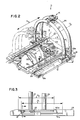
- Holder 10 includes a recessed base plate 12 which is adjustably mounted on a PlexiglasTM assembly base plate 11 which typically forms a permanent part of the patient bed. In its mounted position on assembly base plate 11, holder 10 may be moved in a direction parallel to the longitudinal Z axis by virtue of a plurality of rounded vertical projections on the underside of base plate 12 (see items 31a and 31b on FIGURE 4).
- Base plate 12 is slidably mounted in opposing longitudinal slots 13a and 13b of base plate 11 to thereby permit the entire holder to move within opening 30.
- holder 10 will be initially positioned with respect to assembly base plate 11 before any other adjustments are made to the position of surface coil holder as described in detail below.
- the surface coil holder in accordance with the invention includes five separate means for positioning the MRI RF surface coil 14 relative to the body part being examined, such as the temporomandibular joint or other areas of the human skull. As indicated above, four of those means serve to position and orient the surface coil itself, with the fifth being used to position the patient's head at a desired angle oblique to the longitudinal axis of holder 10.
- FIGURE 1 shows, in general form, the four independently adjustable positioning and securing means, three of which are depicted at 16 and allow the surface coil to be positioned at a predetermined radial distance transverse to the longitudinal axis of holder 10.
- the surface coil may be moved along an orbital path about the longitudinal axis of the holder by way of a pair of parallel cylindrical U-shaped runner guides 26 and 27 which are fixedly secured to opposing runner feet 17 and 18.
- Coil positioning and securing assembly 16 also includes means for moving the surface coil inwardly and outwardly along a given radius transverse to the longitudinal axis, as well as means for rotating surface coil 14 in a step-wise manner about an axis generally parallel to the longitudinal axis by way of the pivoting means shown generally at 25.
- the holder may be positioned at a predetermined point along the longitudinal axis by way of opposing runner feet 17 and 18 which are slidably mounted on holder base plate 12 and cooperate with runner rails 23 and 24, respectively, to allow for movement of holder 10 in either direction parallel to the longitudinal axis.
- Both runner rails 23 and 24 include corresponding identical position indicator markings 29 to facilitate accurate positioning of the holder along the Z axis.
- the body part to be examined may be adjustably positioned relative to surface coil 14 by means of a head cradle 19 which slidably cooperates with a cradle support base (item 38 on FIGURE 2) which in turn is fixedly secured to recessed holder base plate 12.
- the cradle support base 38 includes means as described below for rotating head cradle 19 up to 45 degrees about an axis parallel to the longitudinal Z axis. Means are also provided for securing the head cradle in the desired angular orientation.
- Cradle 19 may also be adjusted in a direction parallel to the longitudinal axis of the holder (see discussion of FIGURE 2 below).
- the patient's head rests on a head support cushion 20 and may be secured into position prior to and during the imaging operation using chin strap 21 and forehead strap 22.
- the surface coil holder in accordance with the invention is preferably used in MRI RF imaging operations relating to the head area.
- the holder could be adapted for other parts of the human body with only minor modifications in structure to, for example, the configuration of cradle 19. Further, those skilled in the art will recognize that all parts of the holder must be non-magnetic in construction using, for example, high density nylon or other rigid plastic material.
- each of the runner guides is disposed transverse to axis L and has a radius of curvature R sufficient to provide clearance for the average human head, together with the associated surface coil imaging apparatus.
- the radial portion of each runner guide terminates in opposing downwardly projecting leg portions shown at 26a, 26b, 27a and 27b having the terminal ends thereof adjustably fixedly secured to runner feet 18 and 17, respectively.
- FIGURE 2 also shows in phantom the direction and amount of movement D for the holder along the longitudinal axis by way of slidably mounted runner feet 18 and 17 which, once in the desired position, may be locked into place by foot locks 28a and 28b.
- the exact desired position of each runner foot may be determined by hairline indicators 39a and 39b secured to each foot with indicator markings 29 on runner rails 23 and 24 indicating the exact longitudinal position of the holder.
- FIGURE 2 also illustrates exemplary means for orienting the patient's temporomandibular joint or other body part to be imaged relative to MRI RF surface coil 14 by adjustably rotating head cradle 19.
- head cradle 19 has a curvilinear configuration which is open at the top and both ends thereof to define a trough-like support structure for the patient's head.
- the cradle may be rotated through an angle of approximately 45 degrees about an axis which is substantially parallel to the longitudinal axis of holder 10.
- the radius of curvature of cradle 19 should be large enough to support and partially enclose the average human skull and deformable cushion head support 20.
- cradle 19 also has a configuration in which the longitudinal side edge portion, e.g., side edge 19a, terminates in a downwardly sloping edge portion 19b which in turn terminates in an arcuate end portion 19c sized to support the neck area of the patient.
- the longitudinal side edge portion e.g., side edge 19a
- the longitudinal side edge portion 19b terminates in a downwardly sloping edge portion 19b which in turn terminates in an arcuate end portion 19c sized to support the neck area of the patient.
- Cradle 19 is supported by a cradle base support structure 38 which has a matching curvilinear configuration and is adjustably secured to holder base plate 12 by means of dowel pins (not shown) on the underside of each end of support 38 which engage one of two sets of dowel pin holes in base plate 12.
- the underside surface of head cradle 19 and the top surface of cradle support structure 38 define a conforming bearing surface for rotational movement of head cradle 19 against its fixed support. That is, cradle 19 slides freely within support base 38 about an axis which is parallel to the longitudinal axis of holder 10.
- the adjustment and securing means for head cradle 19 include a calibrated vernier-like angle plate 32 which is rigidly secured to the rearward end of cradle 19.
- Angle plate 32 has an arcuate configuration and includes an elliptical opening or slot 37 in the center thereof having a radius of curvature slightly less than that of the head cradle itself.
- Angle plate 32 slidably engages pivot pin 34 which passes through slot 37 to be secured to pressure block 35 which in turn is slidably mounted on the top surface of cradle 19.
- Pressure block 35 may be biased in a direction toward arcuate angle plate 32 by turning adjusting and securing knob 33 in a clockwise direction.
- adjusting knob 33 is first loosened to allow the cradle to be rotated about pivot pin 34. Knob 33 is then tightened causing pressure blocks 33 and 35 to press against opposite sides of vernier angle plate 32 and thereby lock the cradle into the desired position.
- the exact angle of rotation is determined by way of a location pointer and indicator marks on the top surface of angle plate 32 with the zero degree line being defined at the center of slot 37.
- a sixth means of positioning anatomical parts is by way of the cradle adjustment along the longitudinal axis of the holder.
- Holder base plate 12 has two sets of dowel pin holes which allow the head cradle assembly to be positioned along the longitudinal axis in two fixed positions. Detachment is done by lifting the cradle assembly so that the dowel pins, which are fixedly secured to the bottom of cradle base support 38 will disengage from the dowel pin holes in base plate 12.
- FIGURE 2 also depicts the relative positions of chin strap 21 and forehead strap 22, which may be adjustably moved in a direction parallel to the longitudinal axis to accommodate an individual patient's head configuration. That is, straps 21 and 22 are slidably mounted within opposing adjusting slots 40a and 40b in the sides of runner rails 23 and 24. As FIGURE 3 illustrates, adjusting slot 40a on the outside of runner rail 23 extends for a distance D2 to allow for the various desired positions for each holding strap.
- FlGURE 3 also shows one aspect of the means for adjusting the relative position of runner feet 23 and 24.
- Longitudinal slot 41a slidably cooperates with the runner foot adjusting and securing means discussed below with respect to FIGURE 10.
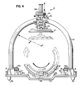
- FIGURE 4 of the drawings shows in greater detail the surface coil orientation locking (securing) means depicted generally as item 16 in FIGURE 1.
- the preferred positioning and securing means consists of two opposing upper and lower adjustable clamping jaws 46 and 47 which are slidably mounted to parallel runner guides 26 and 27.
- Split bottom clamping jaw 47 includes two parallel clamping arms 47a and 47b for clamping engagement with each parallel runner guide on its bottom surface thereof. Each clamping arm thus has dual clamping surfaces with a radius of curvature matching the radius of curvature of the cylindrical runner guides (see also FIGURE 6).
- Top clamping jaw 46 has only a single clamping arm 46a for each parallel runner guide. Each side of arm 46 thus has an upwardly curving clamping surface, also with a radius of curvature matching the runner guides. Together, clamping jaws 46 and 47 slidably encase parallel runner guides 26 and 27 and, prior to tightening, allow the entire coil orientation securing means to be moved in a orbital manner along the runners within a plane defined by the the X and Y axis, i.e., transverse to the longitudinal axis of holder 10.
- Clamping jaws 46 and 47 each have concentric openings therein sized to receive a cylindrical orientation arm 56 which may be moved inwardly and outwardly along an axis transverse to the longitudinal axis of the holder to thereby adjust the position of the surface coil at a prescribed radial distance from the longitudinal axis.
- the coil orientation securing means depicted on FIGURE 4 includes first and second locking knobs 44 and 45, respectively, both of which threadably engage an orientation arm adjustment sleeve (see item 55 on FIGURE 5 and item 60 on FIGURE 6).
- the top orientation arm locking knob 44 serves to tighten cylindrical orientation arm 56 into the desired position while locking knob 45 acts to clamp the clamping jaws 46 and 47 around the parallel runner guides.
- FIGURES 4, 5 and 6 of the drawings further illustrate the means for adjusting and securing surface coil 14 at a predetermined radial distance from the longitudinal axis.
- Adjustable orientation arm 56 slidably cooperates with sleeve 60 having a conical bearing surface which mates with an expandable and contractible conical collet or gripping wedge 59 disposed in the sleeve and surrounding orientation arn 56.
- Conical gripping wedge 59 is capable of being compressed due to the cutout portions along its longitudinal axis when locking knob 44 is turned in a clockwise direction. Cylindrical orientation arm 56 may thus be locked into the desired position by turning locking knob 44 in a clockwise direction which forces gripping wedge 59 into frictional engagement with orientation arm 56. Since conical wedge 59 and the conical surface of sleeve 60 are at slightly different angles, disengagement of conical wedge 59 from cylindrical orientation arm 56 will occur when locking knob 44 is turned counterclockwise.
- Orientation arm 56 also includes a keyway 57 which cooperates with a key 80 in 60 (see FIGURE 14) such that the movement upwardly and downwardly of orientation arm 56 occurs without any rotational movement.
- Orientation arm 56 is also prevented from extending below the top of locking nut 44 by way of flange cap 58 which is threadably secured to the top of the arm.
- FIGURES 4, 5 and 6 also illustrate the means (shown generally as 25) for pivotally adjusting the position of MRI RF surface coil 14.
- Such means includes a gimble-like pivot head 49 which rotates in a step-wise manner about acrylic pivot pin 53 which operatively connects pivot head 49 and cylindrical pivot rod 65 (see FIGURE 7) disposed inside orientation arm 56 and resiliently biased upwardly by spring means.
- Pivot head 49 also includes a pair of opposing rigid detent-engaging fingers 54a and 54b (see FIGURE 8) secured to each side of pivot head 49 which selectively engage one of a plurality of parallel detents 52 in the bottom surface of the upper pivot block 48.
- the detents are arranged along an arc such that the step-wise engagement of fingers 54a and 54b results in a pivotal rotation of the MRI RF surface coil about 15 to 22 degrees relative to the longitudinal axis of orientation arm 56.
- the projecting end portions of the detent-engaging fingers have the same general configuration as the detents themselves.
- the operator In order to rotatably adjust the position of surface coil 14, the operator merely exerts a slight downward pressure to thereby rotate the coil in a step-wise manner (from detent to detent) to the desired angular position.
- the top surface of pivot head 50 and the edges of fixed pivot mounting block 48 also define a bearing surface at the edges between the two components during rotation of the head.
- FIGURE 7 of the drawings depicts the preferred means by which the cylindrical pivot rod 65 may be resiliently biased upwardly. It also illustrates in greater detail the pivot head and means for providing step-wise adjustment of the MRI RF surface coil and shows exemplary means for providing releasably locking engagement between the surface coil and pivot adjustment means 25.
- cylindrical pivot rod 65 is disposed inside orientation arm 56 and connects at the lower end thereof to pivot pin 53.
- the upper end of pivot rod 65 threadably engages spring support washer 63a which "floats" within a cylindrical bore section of orientation arm 56.
- Pivot rod 65 is resiliently biased upwardly by virtue of spring 64 which is compressed between spring support washer 63a and flat washers 63b and 63c which rest on the shoulder of cylindrical bore 66 within orientation arm 56.
- FIGURE 8 of the drawings shows an exploded view of pivot head 50 whereby the projecting detent-engaging fingers 54a and 54b are fixedly secured to corresponding slots in pivot head 50 by virtue of securing pins 69.
- Pivot head 50 may also preferably be made in one piece, such as a solid piece of nylon.
- FIGURE 9 depicts the lower portion of pivot head 50 showing the relative positions of cylindrical pivot rod 65 as connected to pivot pin 53.
- the bottom portion of pivot head 50 contains male threads for engagement with a threaded surface coil attachment knob 51 (see FIGURES 4 and 15) to thereby secure surface coil 14 to the entire pivot means 25.
- the lower threaded portion of pivot head 50 contains two openings, 67 and 68, respectively. Cylindrical opening 67 is sized to receive cylindrical securing pin 79 in surface coil 14 (see FIGURE 14).
- Upper elliptical opening 68 facilitates the engagement of the securing pin into opening 67 at the time surface coil 14 is mounted to the pivot head, thereby allowing securing pin 79 to "snap fit" into opening 67 due to the inherent resilience of the plastic near the elliptical opening.
- FIGURES 10, 11, 12 and 13 Exemplary means for positioning the MRI RF surface coil in a direction parallel to the longitudinal axis of the holder are depicted in FIGURES 10, 11, 12 and 13.
- Such means includes a pair of opposing block-like runner feet 17 and 18, each of which contains dual openings in the top to receive the terminal ends of runner guides 26 and 27.
- Each runner foot is capable of sliding movement along the top surface of holder base plate 12 by virtue of four small wheels (shown by way of example as 74a and 74b) disposed in slots 73a, 73b 73c, and 73d which in turn are rotatably mounted to the feet by way of axles 75 and 76.
- the bottom portion of eacl wheel thereby extends below the bottom surface of the foot to contact the top surface of holder base plate 12.
- Each runner foot also slidably engages a longitudinal rail runner (shown as 23 on FIGURE 10) which is fixedly secured to each side of holder base plate 12.
- Each runner foot operatively connects to slot 41a in the runner rail by virtue of a tension rod 71 disposed in openings within slot 41a and runner foot 17 and secured to latch mechanism 28a.
- Rectangular flange 42a which is rigidly secured to one end of tension rod 71 slidably engages the inside vertical surface of runner rail 23 for sliding movement as the runner foot 17 moves back and forth.
- foot 17 engages runner rail 23 by virtue of a curved foot guide positioner 72 which engages a corresponding matching curved longitudinal slot 90 on the inside of runner rail 23.
- Tension rod 71 is secured to a foot lock mechanism 28a by way of screw 78 and sleeve 100.
- Foot lock mechanism 28a preferably consists of over-the-center (cam-like) pressure latch means which serves to translate the pivotal motion of the latch into rectilinear motion to compress the runner foot to its corresponding runner rail and thereby secure the foot at the desired position along the rail.
- a position indicator (item 39a on FIGURE 2) is affixed to the block and provided with a hairline to facilitate fixing the position of the runner foot relative to each runner rail.
- Corresponding position indicator markings 29 are provided on the top surface of each runner rail.
- each of the two pressure latch mechanisms 28a and 28b are loosened by moving the latch in a direction away from the side of runner foot 17 in the manner depicted in FIGURE 13.
- the holder can be secured into position by turning the pressure latch mechanism in the opposite direction thereby biasing the tension rod in a lateral direction and bringing foot 17 into frictional engagement with runner rail 23 along the matching curved surfaces defined by curved foot guide positioner 72 and longitudinal slot 90.
- each plastic ball bearing 94 is resiliently biased against the inside wall of runner foot 17 by way of spring means 91 which presses against the ball bearing via stop washer 92.
- spring means 91 abuts against a threaded plug 93.
- FIGURES 10 and 12 also depict the manner in which the chin and forehead straps 21 and 22 for the surface coil holder are slidably mounted in slot 40a of runner rail 23 by wrapping each strap around a flange-like pin 77 which is disposed in slot 40a for sliding engagement therewith.
- FIGURE 14 of the drawings shows a cross-sectional view of the assembled pivot means 25 in accordance with the invention attached to the surface coil 14 as discussed above.
- FIGURE 15 similarly provides a detailed cross-sectional view of the pivot head 50 secured to the surface coil by virtue of securing pin 79, also as discussed in detail above.
Landscapes
- Physics & Mathematics (AREA)
- Condensed Matter Physics & Semiconductors (AREA)
- General Physics & Mathematics (AREA)
- Magnetic Resonance Imaging Apparatus (AREA)
Applications Claiming Priority (2)
| Application Number | Priority Date | Filing Date | Title |
|---|---|---|---|
| US114343 | 1987-10-30 | ||
| US07/114,343 US5085219A (en) | 1987-10-30 | 1987-10-30 | Adjustable holders for magnetic reasonance imaging rf surface coil |
Publications (3)
| Publication Number | Publication Date |
|---|---|
| EP0314359A2 true EP0314359A2 (fr) | 1989-05-03 |
| EP0314359A3 EP0314359A3 (en) | 1990-10-03 |
| EP0314359B1 EP0314359B1 (fr) | 1996-01-31 |
Family
ID=22354669
Family Applications (1)
| Application Number | Title | Priority Date | Filing Date |
|---|---|---|---|
| EP88309709A Expired - Lifetime EP0314359B1 (fr) | 1987-10-30 | 1988-10-17 | Support de bobine à haute fréquence pour l'imagerie de l'articulation de mâchoires par résonance magnétique |
Country Status (5)
| Country | Link |
|---|---|
| US (1) | US5085219A (fr) |
| EP (1) | EP0314359B1 (fr) |
| JP (1) | JP2615160B2 (fr) |
| AT (1) | ATE133792T1 (fr) |
| DE (1) | DE3854954D1 (fr) |
Cited By (8)
| Publication number | Priority date | Publication date | Assignee | Title |
|---|---|---|---|---|
| WO1990013045A1 (fr) * | 1989-04-21 | 1990-11-01 | Webb Research Ii, Inc. | Stabilisateur de bobine de surface a position variable pour l'imagerie a resonance magnetique |
| EP0437049A3 (en) * | 1989-12-18 | 1991-11-13 | General Electric Company | Antennae for high-resolution magnetic resonance imaging |
| US5201312A (en) * | 1989-12-18 | 1993-04-13 | General Electric Company | Antennae for high-resolution magnetic resonance imaging of the eye |
| WO1994028431A1 (fr) * | 1993-05-21 | 1994-12-08 | The University Of Queensland | Porte-echantillon pour resonance magnetique nucleaire |
| DE102010011902A1 (de) * | 2010-03-18 | 2011-09-22 | Siemens Aktiengesellschaft | Neurochirurgie-Kopfhalter in Kombination mit einer lokalen Spule |
| DE102012206922A1 (de) * | 2012-04-26 | 2013-10-31 | Siemens Aktiengesellschaft | Empfangsspulensystem |
| RU191929U1 (ru) * | 2019-02-14 | 2019-08-28 | Федеральное государственное бюджетное образовательное учреждение высшего образования "Южно-Уральский государственный медицинский университет" Министерства здравоохранения Российской Федерации (ФГБОУ ВО ЮУГМУ Минздрава России) | Позиционер для функциональной магнитно-резонансной томографии височно-нижнечелюстного сустава |
| EP4624969A1 (fr) * | 2024-03-25 | 2025-10-01 | Elekta Instrument AB | Adaptateur de bobine de tête irm, un kit comprenant l'adaptateur de bobine de tête irm et procédé de fixation de la tête d'un patient par rapport à une bobine de tête irm. |
Families Citing this family (83)
| Publication number | Priority date | Publication date | Assignee | Title |
|---|---|---|---|---|
| JPH0616764B2 (ja) * | 1990-02-07 | 1994-03-09 | 株式会社東芝 | 磁気共鳴イメージングのためのコイル装置 |
| US5154178A (en) * | 1990-10-09 | 1992-10-13 | Sri International | Method and apparatus for obtaining in-vivo nmr data from a moving subject |
| FI91357C (fi) * | 1991-11-15 | 1994-06-27 | Picker Nordstar Oy | Anatominen tuenta MRI-laitteeseen |
| JP2637336B2 (ja) * | 1992-06-30 | 1997-08-06 | 株式会社島津製作所 | 磁気共鳴断層撮影装置 |
| JP3742662B2 (ja) * | 1992-08-05 | 2006-02-08 | ゼネラル・エレクトリック・カンパニイ | 開放形磁気共鳴イメージングに適した磁石 |
| US5388580A (en) * | 1992-08-19 | 1995-02-14 | The United States Of America As Represented By The Department Of Health And Human Services | Head holder for magnetic resonance imaging/spectroscopy system |
| US5307039A (en) * | 1992-09-08 | 1994-04-26 | General Electric Company | Frustoconical magnet for magnetic resonance imaging |
| US5311868A (en) * | 1992-10-07 | 1994-05-17 | Peachtree Research & Development, Inc. | Holder for stereotactic frame |
| US5396171A (en) * | 1993-01-04 | 1995-03-07 | General Electric Company | Field mapping fixture for a superconducting magnet for imaging human limbs |
| JPH06209912A (ja) * | 1993-01-18 | 1994-08-02 | Toshiba Corp | 磁気共鳴イメージング装置 |
| US5323112A (en) * | 1993-03-05 | 1994-06-21 | Varian Associates, Inc. | Reproducibly positionable NMR probe |
| US5361764A (en) * | 1993-07-09 | 1994-11-08 | Grumman Aerospace Corporation | Magnetic resonance imaging foot coil assembly |
| US5520181A (en) * | 1993-11-24 | 1996-05-28 | Technology Funding Secured Investors Ii | Positioning device for producing movement in the shoulder |
| US5521507A (en) * | 1995-02-03 | 1996-05-28 | Advanced Nmr Systems, Inc. | Gradient coil power supply and imaging method |
| DE19511796C2 (de) * | 1995-03-30 | 1998-10-01 | Siemens Ag | Kopfantenne für Magnetresonanzuntersuchungen |
| US5706812A (en) * | 1995-11-24 | 1998-01-13 | Diagnostic Instruments, Inc. | Stereotactic MRI breast biopsy coil and method for use |
| US6084409A (en) * | 1996-07-05 | 2000-07-04 | Siemens Aktiengesellschaft | Magnetic resonance scanner having a unitary radio-frequency arrangement |
| US5836878A (en) * | 1997-08-11 | 1998-11-17 | Wisconsin Alumni Research Foundation | Head restraint method and apparatus for use in MRI |
| USD407820S (en) | 1997-09-29 | 1999-04-06 | Ge Yokogawa Medical Systems, Limited | Wrist holder for MRI apparatus |
| GB2350682A (en) * | 1999-06-04 | 2000-12-06 | Marconi Electronic Syst Ltd | Laterally moveable RF coil for MRI |
| US6315783B1 (en) * | 2000-04-07 | 2001-11-13 | Odin Technologies, Ltd. | Surgical head support |
| US8256430B2 (en) | 2001-06-15 | 2012-09-04 | Monteris Medical, Inc. | Hyperthermia treatment and probe therefor |
| US8190234B2 (en) * | 2000-07-28 | 2012-05-29 | Fonar Corporation | Movable patient support with spatial locating feature |
| US7701209B1 (en) * | 2001-10-05 | 2010-04-20 | Fonar Corporation | Coils for horizontal field magnetic resonance imaging |
| US7906966B1 (en) | 2001-10-05 | 2011-03-15 | Fonar Corporation | Quadrature foot coil antenna for magnetic resonance imaging |
| US6784665B1 (en) * | 2001-11-19 | 2004-08-31 | General Electric Company | Multiple degree of freedom adjustable MRI radio frequency array coil system |
| US7907988B2 (en) * | 2002-04-01 | 2011-03-15 | Ilan Elias | Method and device for generating a passive movement in a diagnostic device |
| DE10235963A1 (de) * | 2002-04-01 | 2003-10-16 | Ilan Elias | Vorrichtung zum Erzeugen einer Passivbewegung eines Patienten in einem Magnet-Resonanz-Tomographen |
| US7551954B2 (en) * | 2002-04-25 | 2009-06-23 | Fonar Corporation | Magnetic resonance imaging with adjustable fixture apparatus |
| US7693570B2 (en) * | 2002-04-25 | 2010-04-06 | Fonar Corporation | Magnetic resonance imaging with adjustable fixture apparatus |
| AU2003233602A1 (en) * | 2002-05-17 | 2003-12-02 | Mr Instruments, Inc. | A cavity resonator for mr systems |
| US6980002B1 (en) * | 2002-11-04 | 2005-12-27 | General Electric Company | Integrated cervical-thoracic-lumbar spine MRI array coil |
| DE102004020783A1 (de) * | 2004-04-27 | 2005-11-24 | Ilan Elias | Diagnosegerät |
| JP2004329726A (ja) * | 2003-05-12 | 2004-11-25 | Hitachi Ltd | 手術装置 |
| US7218106B2 (en) * | 2003-12-04 | 2007-05-15 | Kabushiki Kaisha Toshiba | MRI with automatic contour-controlled separation between RF coil and object being imaged |
| JP4751045B2 (ja) * | 2003-12-04 | 2011-08-17 | 株式会社東芝 | 磁気共鳴イメージング装置 |
| ITSV20040015A1 (it) * | 2004-04-07 | 2004-07-07 | Esaote Spa | Dispositivo porta-paziente, come un lettino od un tavolo oppure una poltrona, e per macchine a risonanza magnetica nucleare, macchina a rosonanza magnetica nucleare e metodo per l'acquisizione di immagini in risonanza magnetica nucleare |
| US7526330B1 (en) * | 2004-07-06 | 2009-04-28 | Pulseteq Limited | Magnetic resonance scanning apparatus |
| CN101229061B (zh) * | 2004-11-02 | 2012-11-21 | 株式会社东芝 | 磁共振成像装置和磁共振成像方法 |
| US8401615B1 (en) | 2004-11-12 | 2013-03-19 | Fonar Corporation | Planar coil flexion fixture for magnetic resonance imaging and use thereof |
| CN100360083C (zh) * | 2004-12-31 | 2008-01-09 | 西门子(中国)有限公司 | 磁共振成像设备线圈的转动定位装置 |
| DE102005021621A1 (de) * | 2005-05-05 | 2006-11-16 | Hubert Noras | Empfangsspulen-Halterung für ein MR-Bildgebungssystem |
| US7659719B2 (en) * | 2005-11-25 | 2010-02-09 | Mr Instruments, Inc. | Cavity resonator for magnetic resonance systems |
| DE102006012404A1 (de) * | 2006-03-17 | 2007-09-20 | Siemens Ag | Magnetresonanzanlage |
| WO2007109358A2 (fr) * | 2006-03-21 | 2007-09-27 | Fonar Corporation | Système pour chirurgie assistée par imagerie par résonance magnétique |
| JP4854448B2 (ja) * | 2006-09-28 | 2012-01-18 | 株式会社東芝 | Mri装置及びmri装置用rfコイルユニット |
| US7489133B1 (en) * | 2007-02-28 | 2009-02-10 | Midwest Composite Technologies, Inc. | Tray for positioning an object within an imaging coil |
| WO2008104522A2 (fr) * | 2007-02-28 | 2008-09-04 | Esaote Spa | Appareil d'imagerie par résonance magnétique |
| EP2134235A4 (fr) * | 2007-03-27 | 2015-04-22 | Olympus Medical Systems Corp | Appareil d'endoscopie |
| US8175677B2 (en) * | 2007-06-07 | 2012-05-08 | MRI Interventions, Inc. | MRI-guided medical interventional systems and methods |
| JP2009261814A (ja) * | 2008-04-30 | 2009-11-12 | Ge Medical Systems Global Technology Co Llc | 磁気刺激用コイル、磁気刺激装置、および磁気刺激システム |
| DE102009027119B4 (de) | 2009-06-23 | 2013-01-17 | Sirona Dental Systems Gmbh | Magnetfeldeinheit eines MRT-Systems zur bildgebenden Erfassung eines Kopfbereichs |
| KR101109911B1 (ko) * | 2010-01-19 | 2012-02-29 | 가톨릭대학교 산학협력단 | 치과용 rf 코일, 머리고정 유닛, 및 그것들을 구비한 자기공명영상 시스템 |
| US9655542B2 (en) | 2010-09-29 | 2017-05-23 | Aspect Imaging Ltd. | MRI with magnet assembly adapted for convenient scanning of laboratory animals with automated RF tuning unit |
| DE202011051413U1 (de) | 2010-09-29 | 2012-01-09 | Aspect Magnet Technologies Ltd. | Magnetresonanztomograf mit Magnetenanordnung zum praktischen Scannen von Versuchstieren |
| US10292617B2 (en) | 2010-09-30 | 2019-05-21 | Aspect Imaging Ltd. | Automated tuning and frequency matching with motor movement of RF coil in a magnetic resonance laboratory animal handling system |
| CN104254296A (zh) * | 2011-04-08 | 2014-12-31 | 曼特瑞斯医药有限责任公司 | 头部固定系统和方法 |
| RU2589761C2 (ru) | 2011-04-18 | 2016-07-10 | Конинклейке Филипс Н.В. | Безопасный замок быстрого доступа для катушки приемника мрт |
| WO2013075226A2 (fr) * | 2011-11-26 | 2013-05-30 | Xlr Imaging Inc. | Dispositif d'installation d'un patient et de positionnement de sa tête |
| US10732244B2 (en) | 2012-03-26 | 2020-08-04 | Sirona Dental Systems Gmbh | Systems, methods, apparatuses, and computer-readable storage media for performing diagnostic examinations using MRI |
| EP2866723A4 (fr) | 2012-06-27 | 2016-12-14 | Monteris Medical Corp | Thérapie guidée par image d'un tissu |
| US10595744B2 (en) * | 2014-02-14 | 2020-03-24 | MRI Interventions, Inc. | Surgical tool-positioning devices and related methods |
| US9504484B2 (en) | 2014-03-18 | 2016-11-29 | Monteris Medical Corporation | Image-guided therapy of a tissue |
| US10675113B2 (en) | 2014-03-18 | 2020-06-09 | Monteris Medical Corporation | Automated therapy of a three-dimensional tissue region |
| US9492121B2 (en) | 2014-03-18 | 2016-11-15 | Monteris Medical Corporation | Image-guided therapy of a tissue |
| US20170245779A1 (en) * | 2014-10-17 | 2017-08-31 | National Research Council Of Canada | Pressing apparatus for magnetic resonance imaging and spectroscopy |
| EP3264979A1 (fr) * | 2015-03-04 | 2018-01-10 | Koninklijke Philips N.V. | Ensemble table de patient |
| US10327830B2 (en) | 2015-04-01 | 2019-06-25 | Monteris Medical Corporation | Cryotherapy, thermal therapy, temperature modulation therapy, and probe apparatus therefor |
| JP6641844B2 (ja) | 2015-09-30 | 2020-02-05 | 株式会社Ihi | 充填材 |
| CA3007340C (fr) | 2016-01-27 | 2020-10-27 | Synaptive Medical (Barbados) Inc. | Systeme de bobine de tete et procedes pour ameliorer et/ou optimiser une irm |
| US10809324B2 (en) | 2016-08-03 | 2020-10-20 | Indiana University Research And Technology Corporation | Support for an electronic tablet for use in functional MRI |
| WO2018195654A1 (fr) * | 2017-04-26 | 2018-11-01 | Polyvalor, Limited Partnership | Appareil et procédé de bobine d'irm |
| CN110200630B (zh) * | 2019-05-24 | 2023-06-23 | 上海联影医疗科技股份有限公司 | 用于磁共振成像的线圈支架及磁共振成像设备 |
| JP7270510B2 (ja) * | 2019-09-06 | 2023-05-10 | キヤノンメディカルシステムズ株式会社 | 医用画像診断装置及び心拍計測装置 |
| US11231472B2 (en) * | 2019-09-06 | 2022-01-25 | Quality Electrodynamics, Llc | Adaptive coil base |
| WO2021154574A1 (fr) | 2020-01-31 | 2021-08-05 | Clearpoint Neuro, Inc. | Systèmes de support d'outil chirurgical comprenant des pieds de support allongés avec des longueurs ajustables et procédés associés |
| WO2022036305A1 (fr) * | 2020-08-14 | 2022-02-17 | The Research Foundation for the State Universtiy of New York | Appareils de protection faciale et systèmes les comprenant |
| CN112353380B (zh) * | 2020-10-14 | 2024-08-23 | 上海联影医疗科技股份有限公司 | 用于动物扫描的线圈定位结构及磁共振动物扫描设备 |
| KR102297904B1 (ko) * | 2020-11-19 | 2021-09-07 | 주식회사 이온메디칼 | 마이크로웨이브를 이용한 피부 치료 장치 |
| CN115363563B (zh) * | 2022-08-17 | 2023-11-28 | 浙江大学 | 一种适用头部核磁共振成像的优化定位装置 |
| CA3255410A1 (fr) * | 2023-03-01 | 2024-09-06 | NeuraNova, Inc. | Système de positionnement de bobine pour capteur cérébral non invasif |
| IT202300007260A1 (it) * | 2023-04-14 | 2024-10-14 | Esaote Spa | Sistema per l’acquisizione di immagini in risonanza magnetica intraoperatoria |
| EP4455705A1 (fr) * | 2023-04-28 | 2024-10-30 | Siemens Healthineers AG | Bobine locale et dispositif de résonance magnétique |
Family Cites Families (21)
| Publication number | Priority date | Publication date | Assignee | Title |
|---|---|---|---|---|
| US2220113A (en) * | 1937-11-01 | 1940-11-05 | Dow Chemical Co | Mixed triaryl phosphites |
| US2210113A (en) * | 1938-06-02 | 1940-08-06 | Carolyn L Brock | Head and chin support |
| US2966588A (en) * | 1952-12-15 | 1960-12-27 | Gen Electric | X-ray apparatus |
| US3025397A (en) * | 1959-06-11 | 1962-03-13 | Travis | Skull radiography apparatus |
| DE2238706A1 (de) * | 1972-08-05 | 1974-02-07 | Koch & Sterzel Kg | Roentgenroehrenstativ mit einem cbogen |
| DE2348039C3 (de) * | 1973-09-24 | 1984-05-10 | Siemens AG, 1000 Berlin und 8000 München | Röntgenuntersuchungsgerät |
| NL7607976A (nl) * | 1976-07-19 | 1978-01-23 | Optische Ind De Oude Delft Nv | Inrichting voor tomografie met voorzieningen waardoor signaalprofielen afgeleid van een di- vergerende stralingsbundel kunnen worden gere- construeerd in signaalprofielen die elk corre- sponderen met een bundel van evenwijdig inval- lende stralen. |
| US4256112A (en) * | 1979-02-12 | 1981-03-17 | David Kopf Instruments | Head positioner |
| US4341220A (en) * | 1979-04-13 | 1982-07-27 | Pfizer Inc. | Stereotactic surgery apparatus and method |
| US4608977A (en) * | 1979-08-29 | 1986-09-02 | Brown Russell A | System using computed tomography as for selective body treatment |
| NL7908545A (nl) * | 1979-11-23 | 1981-06-16 | Philips Nv | Inrichting voor het bepalen van een stralingsabsorptie- verdeling in een vlak van een lichaam. |
| US4465069A (en) * | 1981-06-04 | 1984-08-14 | Barbier Jean Y | Cranial insertion of surgical needle utilizing computer-assisted tomography |
| US4463758A (en) * | 1981-09-18 | 1984-08-07 | Arun A. Patil | Computed tomography stereotactic frame |
| FI65365C (fi) * | 1982-07-07 | 1984-05-10 | Instrumentarium Oy | Spolanordning |
| JPS606505U (ja) * | 1983-06-22 | 1985-01-17 | 株式会社日立製作所 | ベツド機構 |
| JPS6024831A (ja) * | 1983-07-20 | 1985-02-07 | 横河メデイカルシステム株式会社 | 核磁気共鳴検出器 |
| US4821729A (en) * | 1984-05-08 | 1989-04-18 | The Johns Hopkins University | Means and method for the noninvasive fragmentation of body concretions having means for accurately locating a concretion |
| JPS6171103U (fr) * | 1984-10-15 | 1986-05-15 | ||
| US4592352A (en) * | 1984-11-30 | 1986-06-03 | Patil Arun A | Computer-assisted tomography stereotactic system |
| JPS62299247A (ja) * | 1986-06-20 | 1987-12-26 | 株式会社日立製作所 | Mri装置用サ−フエイスコイルユニツト |
| DE3628035A1 (de) * | 1986-08-19 | 1988-02-25 | Siemens Ag | Oberflaechenspulenanordnung fuer die untersuchung der kernmagnetischen resonanz |
-
1987
- 1987-10-30 US US07/114,343 patent/US5085219A/en not_active Expired - Lifetime
-
1988
- 1988-10-17 AT AT88309709T patent/ATE133792T1/de active
- 1988-10-17 EP EP88309709A patent/EP0314359B1/fr not_active Expired - Lifetime
- 1988-10-17 DE DE3854954T patent/DE3854954D1/de not_active Expired - Lifetime
- 1988-10-31 JP JP63275993A patent/JP2615160B2/ja not_active Expired - Lifetime
Cited By (9)
| Publication number | Priority date | Publication date | Assignee | Title |
|---|---|---|---|---|
| WO1990013045A1 (fr) * | 1989-04-21 | 1990-11-01 | Webb Research Ii, Inc. | Stabilisateur de bobine de surface a position variable pour l'imagerie a resonance magnetique |
| EP0437049A3 (en) * | 1989-12-18 | 1991-11-13 | General Electric Company | Antennae for high-resolution magnetic resonance imaging |
| US5201312A (en) * | 1989-12-18 | 1993-04-13 | General Electric Company | Antennae for high-resolution magnetic resonance imaging of the eye |
| WO1994028431A1 (fr) * | 1993-05-21 | 1994-12-08 | The University Of Queensland | Porte-echantillon pour resonance magnetique nucleaire |
| DE102010011902A1 (de) * | 2010-03-18 | 2011-09-22 | Siemens Aktiengesellschaft | Neurochirurgie-Kopfhalter in Kombination mit einer lokalen Spule |
| DE102010011902B4 (de) | 2010-03-18 | 2018-05-24 | Siemens Healthcare Gmbh | Neurochirurgie-Kopfhalter in Kombination mit einer lokalen Spule |
| DE102012206922A1 (de) * | 2012-04-26 | 2013-10-31 | Siemens Aktiengesellschaft | Empfangsspulensystem |
| RU191929U1 (ru) * | 2019-02-14 | 2019-08-28 | Федеральное государственное бюджетное образовательное учреждение высшего образования "Южно-Уральский государственный медицинский университет" Министерства здравоохранения Российской Федерации (ФГБОУ ВО ЮУГМУ Минздрава России) | Позиционер для функциональной магнитно-резонансной томографии височно-нижнечелюстного сустава |
| EP4624969A1 (fr) * | 2024-03-25 | 2025-10-01 | Elekta Instrument AB | Adaptateur de bobine de tête irm, un kit comprenant l'adaptateur de bobine de tête irm et procédé de fixation de la tête d'un patient par rapport à une bobine de tête irm. |
Also Published As
| Publication number | Publication date |
|---|---|
| US5085219A (en) | 1992-02-04 |
| EP0314359A3 (en) | 1990-10-03 |
| EP0314359B1 (fr) | 1996-01-31 |
| DE3854954D1 (de) | 1996-03-14 |
| JPH021239A (ja) | 1990-01-05 |
| ATE133792T1 (de) | 1996-02-15 |
| JP2615160B2 (ja) | 1997-05-28 |
Similar Documents
| Publication | Publication Date | Title |
|---|---|---|
| EP0314359B1 (fr) | Support de bobine à haute fréquence pour l'imagerie de l'articulation de mâchoires par résonance magnétique | |
| US6813788B2 (en) | Variable length radiolucent surgical table extension | |
| US6003174A (en) | Radiolucent table extension and method | |
| US5618288A (en) | Stereotactic system for surgical procedures | |
| US5855582A (en) | Noninvasive stereotactic apparatus and method for relating data between medical devices | |
| EP1152727B1 (fr) | Adaptateur articule pour extension de table radiotransparente | |
| CA1289030C (fr) | Cadre pour le support d'instruments chirurgicaux au site d'une incision chirurgicale | |
| EP0904741B1 (fr) | Dispositif de support pour un instrument de chirurgie | |
| US5947981A (en) | Head and neck localizer | |
| EP1267743B1 (fr) | Rallonge de table d'operation radiotransparente et methode | |
| EP1009284B1 (fr) | Ensemble extension de table permeable aux rayons x | |
| US4791371A (en) | Apparatus useful in magnetic resonance imaging | |
| US20100116278A1 (en) | Single screw activated double axle locking mechanism | |
| US4071231A (en) | Pneumoencephalography chair | |
| US7430773B2 (en) | Device to facilitate controlled rotation of the cervical spine | |
| US8845654B2 (en) | Scaled head frame positioner and tabletop adapter | |
| US12396821B2 (en) | Devices for assisting neurosurgical interventions | |
| US5010881A (en) | Orthopedic fixation device | |
| US7613494B2 (en) | Apparatus and methods for imaging using an anatomical positioning system | |
| US7174587B2 (en) | Patient positioning device for radiation therapy | |
| JPH067463A (ja) | 放射線治療用頭部定位器の微動位置合わせ装置 | |
| JP2702017B2 (ja) | 医療用頭蓋固定装置 | |
| CN220404353U (zh) | 手术辅助定位架及手术床 | |
| JP3215773B2 (ja) | 頭蓋固定装置 | |
| CN213941858U (zh) | 一种介入放射用导管固定器 |
Legal Events
| Date | Code | Title | Description |
|---|---|---|---|
| PUAI | Public reference made under article 153(3) epc to a published international application that has entered the european phase |
Free format text: ORIGINAL CODE: 0009012 |
|
| AK | Designated contracting states |
Kind code of ref document: A2 Designated state(s): AT BE CH DE ES FR GB GR IT LI LU NL SE |
|
| PUAL | Search report despatched |
Free format text: ORIGINAL CODE: 0009013 |
|
| AK | Designated contracting states |
Kind code of ref document: A3 Designated state(s): AT BE CH DE ES FR GB GR IT LI LU NL SE |
|
| RHK1 | Main classification (correction) |
Ipc: A61B 19/00 |
|
| 17P | Request for examination filed |
Effective date: 19901227 |
|
| 17Q | First examination report despatched |
Effective date: 19940228 |
|
| GRAA | (expected) grant |
Free format text: ORIGINAL CODE: 0009210 |
|
| AK | Designated contracting states |
Kind code of ref document: B1 Designated state(s): AT BE CH DE ES FR GB GR IT LI LU NL SE |
|
| PG25 | Lapsed in a contracting state [announced via postgrant information from national office to epo] |
Ref country code: IT Free format text: LAPSE BECAUSE OF FAILURE TO SUBMIT A TRANSLATION OF THE DESCRIPTION OR TO PAY THE FEE WITHIN THE PRE;WARNING: LAPSES OF ITALIAN PATENTS WITH EFFECTIVE DATE BEFORE 2007 MAY HAVE OCCURRED AT ANY TIME BEFORE 2007. THE CORRECT EFFECTIVE DATE MAY BE DIFFERENT FROM THE ONE RECORDED.SCRIBED TIME-LIMIT Effective date: 19960131 Ref country code: BE Effective date: 19960131 Ref country code: AT Effective date: 19960131 Ref country code: CH Effective date: 19960131 Ref country code: NL Free format text: LAPSE BECAUSE OF FAILURE TO SUBMIT A TRANSLATION OF THE DESCRIPTION OR TO PAY THE FEE WITHIN THE PRESCRIBED TIME-LIMIT Effective date: 19960131 Ref country code: ES Free format text: THE PATENT HAS BEEN ANNULLED BY A DECISION OF A NATIONAL AUTHORITY Effective date: 19960131 Ref country code: FR Effective date: 19960131 Ref country code: LI Effective date: 19960131 Ref country code: GR Free format text: LAPSE BECAUSE OF FAILURE TO SUBMIT A TRANSLATION OF THE DESCRIPTION OR TO PAY THE FEE WITHIN THE PRESCRIBED TIME-LIMIT Effective date: 19960131 |
|
| REF | Corresponds to: |
Ref document number: 133792 Country of ref document: AT Date of ref document: 19960215 Kind code of ref document: T |
|
| REF | Corresponds to: |
Ref document number: 3854954 Country of ref document: DE Date of ref document: 19960314 |
|
| PG25 | Lapsed in a contracting state [announced via postgrant information from national office to epo] |
Ref country code: SE Effective date: 19960430 |
|
| PG25 | Lapsed in a contracting state [announced via postgrant information from national office to epo] |
Ref country code: DE Effective date: 19960501 |
|
| EN | Fr: translation not filed | ||
| NLV1 | Nl: lapsed or annulled due to failure to fulfill the requirements of art. 29p and 29m of the patents act | ||
| REG | Reference to a national code |
Ref country code: CH Ref legal event code: PL |
|
| PGFP | Annual fee paid to national office [announced via postgrant information from national office to epo] |
Ref country code: GB Payment date: 19960925 Year of fee payment: 9 |
|
| PG25 | Lapsed in a contracting state [announced via postgrant information from national office to epo] |
Ref country code: LU Free format text: LAPSE BECAUSE OF NON-PAYMENT OF DUE FEES Effective date: 19961031 |
|
| PLBE | No opposition filed within time limit |
Free format text: ORIGINAL CODE: 0009261 |
|
| STAA | Information on the status of an ep patent application or granted ep patent |
Free format text: STATUS: NO OPPOSITION FILED WITHIN TIME LIMIT |
|
| 26N | No opposition filed | ||
| PG25 | Lapsed in a contracting state [announced via postgrant information from national office to epo] |
Ref country code: GB Free format text: LAPSE BECAUSE OF NON-PAYMENT OF DUE FEES Effective date: 19971017 |
|
| GBPC | Gb: european patent ceased through non-payment of renewal fee |
Effective date: 19971017 |