EP0314361A2 - Elektronisches Sicherheitsschloss - Google Patents
Elektronisches Sicherheitsschloss Download PDFInfo
- Publication number
- EP0314361A2 EP0314361A2 EP88309716A EP88309716A EP0314361A2 EP 0314361 A2 EP0314361 A2 EP 0314361A2 EP 88309716 A EP88309716 A EP 88309716A EP 88309716 A EP88309716 A EP 88309716A EP 0314361 A2 EP0314361 A2 EP 0314361A2
- Authority
- EP
- European Patent Office
- Prior art keywords
- key
- code
- coupled
- control circuit
- memory
- Prior art date
- Legal status (The legal status is an assumption and is not a legal conclusion. Google has not performed a legal analysis and makes no representation as to the accuracy of the status listed.)
- Granted
Links
- 230000007246 mechanism Effects 0.000 claims abstract description 22
- 238000004891 communication Methods 0.000 claims abstract description 5
- 230000004044 response Effects 0.000 claims description 7
- 230000002035 prolonged effect Effects 0.000 claims description 4
- 230000005611 electricity Effects 0.000 claims 3
- 230000000994 depressogenic effect Effects 0.000 description 5
- 230000006870 function Effects 0.000 description 5
- 238000010586 diagram Methods 0.000 description 3
- 230000001419 dependent effect Effects 0.000 description 2
- 238000000034 method Methods 0.000 description 2
- WHXSMMKQMYFTQS-UHFFFAOYSA-N Lithium Chemical compound [Li] WHXSMMKQMYFTQS-UHFFFAOYSA-N 0.000 description 1
- 230000008901 benefit Effects 0.000 description 1
- 230000008878 coupling Effects 0.000 description 1
- 238000010168 coupling process Methods 0.000 description 1
- 238000005859 coupling reaction Methods 0.000 description 1
- 239000013078 crystal Substances 0.000 description 1
- 238000003780 insertion Methods 0.000 description 1
- 230000037431 insertion Effects 0.000 description 1
- 230000003993 interaction Effects 0.000 description 1
- 229910052744 lithium Inorganic materials 0.000 description 1
- 238000012544 monitoring process Methods 0.000 description 1
- 231100000989 no adverse effect Toxicity 0.000 description 1
- 230000003287 optical effect Effects 0.000 description 1
- 230000002093 peripheral effect Effects 0.000 description 1
- 239000010453 quartz Substances 0.000 description 1
- VYPSYNLAJGMNEJ-UHFFFAOYSA-N silicon dioxide Inorganic materials O=[Si]=O VYPSYNLAJGMNEJ-UHFFFAOYSA-N 0.000 description 1
- 230000005236 sound signal Effects 0.000 description 1
- 238000012546 transfer Methods 0.000 description 1
Images


Classifications
-
- G—PHYSICS
- G07—CHECKING-DEVICES
- G07C—TIME OR ATTENDANCE REGISTERS; REGISTERING OR INDICATING THE WORKING OF MACHINES; GENERATING RANDOM NUMBERS; VOTING OR LOTTERY APPARATUS; ARRANGEMENTS, SYSTEMS OR APPARATUS FOR CHECKING NOT PROVIDED FOR ELSEWHERE
- G07C9/00—Individual registration on entry or exit
- G07C9/00174—Electronically operated locks; Circuits therefor; Nonmechanical keys therefor, e.g. passive or active electrical keys or other data carriers without mechanical keys
- G07C9/00182—Electronically operated locks; Circuits therefor; Nonmechanical keys therefor, e.g. passive or active electrical keys or other data carriers without mechanical keys operated with unidirectional data transmission between data carrier and locks
-
- G—PHYSICS
- G07—CHECKING-DEVICES
- G07C—TIME OR ATTENDANCE REGISTERS; REGISTERING OR INDICATING THE WORKING OF MACHINES; GENERATING RANDOM NUMBERS; VOTING OR LOTTERY APPARATUS; ARRANGEMENTS, SYSTEMS OR APPARATUS FOR CHECKING NOT PROVIDED FOR ELSEWHERE
- G07C9/00—Individual registration on entry or exit
- G07C9/00174—Electronically operated locks; Circuits therefor; Nonmechanical keys therefor, e.g. passive or active electrical keys or other data carriers without mechanical keys
- G07C2009/00753—Electronically operated locks; Circuits therefor; Nonmechanical keys therefor, e.g. passive or active electrical keys or other data carriers without mechanical keys operated by active electrical keys
- G07C2009/00761—Electronically operated locks; Circuits therefor; Nonmechanical keys therefor, e.g. passive or active electrical keys or other data carriers without mechanical keys operated by active electrical keys with data transmission performed by connected means, e.g. mechanical contacts, plugs, connectors
-
- G—PHYSICS
- G07—CHECKING-DEVICES
- G07C—TIME OR ATTENDANCE REGISTERS; REGISTERING OR INDICATING THE WORKING OF MACHINES; GENERATING RANDOM NUMBERS; VOTING OR LOTTERY APPARATUS; ARRANGEMENTS, SYSTEMS OR APPARATUS FOR CHECKING NOT PROVIDED FOR ELSEWHERE
- G07C9/00—Individual registration on entry or exit
- G07C9/00174—Electronically operated locks; Circuits therefor; Nonmechanical keys therefor, e.g. passive or active electrical keys or other data carriers without mechanical keys
- G07C9/00857—Electronically operated locks; Circuits therefor; Nonmechanical keys therefor, e.g. passive or active electrical keys or other data carriers without mechanical keys where the code of the data carrier can be programmed
-
- Y—GENERAL TAGGING OF NEW TECHNOLOGICAL DEVELOPMENTS; GENERAL TAGGING OF CROSS-SECTIONAL TECHNOLOGIES SPANNING OVER SEVERAL SECTIONS OF THE IPC; TECHNICAL SUBJECTS COVERED BY FORMER USPC CROSS-REFERENCE ART COLLECTIONS [XRACs] AND DIGESTS
- Y10—TECHNICAL SUBJECTS COVERED BY FORMER USPC
- Y10T—TECHNICAL SUBJECTS COVERED BY FORMER US CLASSIFICATION
- Y10T70/00—Locks
- Y10T70/70—Operating mechanism
- Y10T70/7051—Using a powered device [e.g., motor]
- Y10T70/7062—Electrical type [e.g., solenoid]
- Y10T70/7068—Actuated after correct combination recognized [e.g., numerical, alphabetical, or magnet[s] pattern]
- Y10T70/7073—Including use of a key
Definitions
- This invention relates to an integrated electronic security lock employing an electronic key which may be encoded by means of a control system coupled to the lock.
- Magnetic card keys also exist wherein a secret number is magnetically stored on the card, similar to the system employed in bank service cards.
- the user inserts the card into a suitable receptacle, and enters his personal code via a computer keyboard. Access will be granted only if the code thus entered corresponds to that stored magnetically on the card key.
- Such systems require the user to remember his personal code, and this effectively limits the total number permutations of the code digits and, therefore, the security of the code. Thus, for example, if the code has only four digits, then the maximum number of permutations of the code is 10'000, assuming that each digit can have any value from 0 to 9.
- such magnetic key cards may only be copied or encoded using special equipment which generally puts them out of the range of the domestic market.
- Hotel security systems which employ magnetic coded key cards, the security system comprising a computerized control unit by means of which the code corresponding to each hotel room may easily be changed.
- an integrated electronic security lock comprising: a lock mechanism activated by a motor responsive to a control circuit, and an electronic key containing a first memory for storing a first code, said key being adapted to be coupled to the said control circuit and being provided with communication means for communicating with the said control circuit; said control circuit including: power supply means for supplying d.c.
- computing means power to the said control circuit, computing means, a second memory coupled to the said computing means for storing a second code, a third memory coupled to the said computing means for storing a predetermined instruction set, status determination means for determining the status (locked or unlocked) of said lock mechanism, first selection means for inverting the said status, checking means for comparing the said first and second codes thereby identifying whether the said key is valid, second selection means responsive to the said checking means for generating new first and second codes and storing the said codes in the said first and second memory, respectively, and third selection means responsive to the said checking means for copying the said first code to the first memory of another key or keys.
- the electronic key is a sealed unit containing a NOVRAM (non-volatile random access memory) powered by an internal lithium cell, which NOVRAM is able to store information in the invent of power failiure.
- NOVRAM non-volatile random access memory
- the key is provided with external pins for coupling to the security lock control circuit via a suitable receptacle provided therein.
- the key pins include pins for providing power to the key as well as writing data thereto and reading data therefrom. Additionally, one pin permits connection of a clock synchronizing signal and another pin is used in order to reset the NOVRAM.
- a code may be stored indefinitely in the key and may be read by the security lock control circuit which is also adapted to write a new code to the key.
- the key device provided is devided into three major parts, of which the first two are password areas allowing (or alternatively preventing) access to the key; and the last part is the actual storage of the active system codes.
- the said active code area is divided into four zones (or any other required number of zones), having a zone A of highest priority, followed by a zone B of secondary priority and so on; so that when the key is entered into any coded system, the system will search for the appropriate code zone on the key and will react according to the preset priority; so that the zones A through D will not open door systems, only the highest priority key will open all the systems.
- Each of the said systems could generate new system codes, effecting only the portion of the active code zone in that particular system leaving all the other code zones intact.
- a control panel situated within the premises permits the owner of the premises to lock and unlock the door from the inside, without using the key.
- Other functions may also be activated by inserting a valid key into the key receptacle, following which the user may request the control circuit to generate a new code for subsequent storage within the key, whose secret code is thereby immediately changed.
- the computing means is preferably constituted by a micrtoprocessor containing an "active" code which, at the request of the user, may automatically be copied to any number of other keys.
- an audio monitoring system which produces an audio feedback signal in response to each procedure performed by the user.
- the connection is acknowledged by an audio signal which continues to sound until the key is removed, thereby cautioning the user against leaving his key in the receptacle inadvertently.
- a comprehensive alarm system which is adapted to prevent the user from locking the premises from the outside whilst access is still available to the building through open windows and so on.
- the alarm will also sound if an invalid key is inserted into the receptacle or if the lock mechanism is interfered with.
- Also built into the system is a series of power failure safety features.
- the user is provided with mechanical means for unlocking the door independent of the motor mechanism, in the event of a power failiure. Relatively short power failures have no adverse effect on the control systems, since this is provided with automatic recharegable battery back-up.
- the battery back-up is maintained fully charged via the mains supply, and operates automatically in the event of mains power failure.
- a basic code stored within an EPROM is automatically written to the microprocessor memory as soon as the power is returned.
- the user is then able to gain access to the premises by means of a seperate key programmed with the same basic code, and is then able to generate a new active code which can be copied to any number of other keys.
- microprocessor memory storing the active code and the memory within the key contain 256 bits of information. Thus, the total number of permutations is enourmous. It will thus be clear that the invention provides a high security access system which is nevertheless also highly flexible.
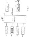
- a microprocessor 1 which derives its clock signals by means of an internal clock whose reference signals are provided by a quartz crystal 2.
- An instruction set for the microprocessor is stored in an EPROM 4 which is enabled by a chip enable pulse provided by the microprocessor 1.
- a local oscillator 6 Connected to the microprocessor 1 is a local oscillator 6 coupled to a loudspeaker 7.
- the local oscillator 6 is coupled to the microprocessor 1 so as to produce a variable frequency audible tone on the loudspeaker 7 in response to instructions from the microprocessor 1.
- a key receptacle 9 which, in a preferred embodiment, contains five sockets into which corresponding pins of an external key may be inserted.
- Three output lines from the microprocessor 1 are connected to a bank of three selector switches 10 which permit selected instructions within the EPROM 4 to be initiated.
- the microprocessor 1 is also connected to a lock mechanism 12 which is fitted inside a door (not shown).
- the microprocessor 1 is also coupled to an alarm 14 which is integrated within the system so as to render it secure.
- the alarm 14 may be a standard intruder alarm system provided with a plurality of sensors which monitor the status (i.e. locked or unlocked) of selected doors and windows within the building.
- Such alarm systems generally have "safe” and “unsafe” states corresponding, respectively, to the situation wherein all the monitored entrances are locked and to that where at least one entrance is unlocked.
- the alarm system 14 is so integrated with the control system, constituted by the microprocessors 1 and its associated circuitry, that the door may not be locked from the outside whilst the status of the alarm system is "unsafe".
- Fig. 2 shows a simplified mechanical arrangement of the lock mechanism 12 shown functionally in Fig. 1.
- the lock mechanism is shown schematically by means of a drive wheel 20 provided with peripheral teeth 21.
- Locking bars 22, 23, 24 and 25 are so connected to the drive wheel 20 that they are either retracted or extended according to the direction of motion of the drive wheel 20.
- the number of locking bars and the exact mechanical arrangement by which they are operated is not a feature of the invention, it being important only that they can be adpated to operate from a single drive wheel.
- microswitches 27 and 29 Mounted adjacent to one of the drive locks 25 are two normally open microswitches 27 and 29 which are adapted to be closed via a small protrusion 30 so connected to the locking bar 25 that the microswith 27 is closed when the locking bar 25 is fully retracted and the microswitch 29 is closed when the locking bar is fully extended.
- the microswitch 29 is closed and, conversely, when the door is unlocked the microswich 27 is closed.
- the drive wheel 20 is rotated by means of a worm gear 32 driven by a motor 34 which is connected to the worm gear 32 by a shaft 35. Also mounted on the shaft 35 is a standard gear wheel 37 whose teeth are adapted to mesh with the teeth of a second, larger, gear wheel 38 mounted on a shaft 39.
- a window 40 is provided on the internal surface of the door through which a part of the periphery of the gear wheel 38 protrudes.
- the motor 34 is a compact, high power device and is connected to the microprocessor 1 via two lines which control the direction of rotation of the motor 34.
- the use of a worm gear 32 provides a high mechanical advantage and also prevents the drive wheel 20 from being rotated manually.
- the gear chain comprising gear wheel 37 and 38 is provided as a safety device in case the power to the motor 34 is interrupted.
- the gear wheel 38 may be turned manually through the window 40 from within the building, thereby turning the shaft 35 via gear wheel 37 and so turning the drive wheel 20 in a direction dependent upon the direction of rotation of the gear wheel 38.
- this provides a method of locking or unlocking the door manually from within the building in the event of a power failiure.
- the two microswitches 27 and 29 are respectively coupled to the microprocessor 1 and provide a means of determining the status of the door (i.e. unlocked or locked). When the lock mechanism is operating there will be a small time interval wherein the protrusion 30 on the locking bar 25 is between the two microswitches 27 and 29. In this condition, both the microswitches 27 and 29 will be open. the microprocessor 1 is so programmed that if both the microswitches 27 and 29 are open for a period of time substantially greater than that taken for the lock mechanism to invert the status from locked to unlocked, or vice versa, the alarm 14 will become energised.
- the two microswitches 27 and 29 constitute status determination means which is adapted to discourage tampering with the system by a would-be intruder.
- a magnet switch is located within the door frame so as to be operated when the door is closed.
- the magnet switch (not shown) is coupled to the microprocessor 1 which is adapted to prevent the lock mechanism operating when the magnet switch indicates that the door is open.
- the system is operated by inserting a valid key into the key receptacle 9 shown in Fig. 1.
- the key itself (not shown) is not a feature of the invention and any suitable device may be used which contains a NOVRAM which can be written to, or read by, the microprocessor 1.
- the key is provided with five pins which engage the sockets of the key receptacle, so as to provide electrical contact with corresponding terminals in the key receptacle.
- One of the pins provides serial data communication between the key and the microprocessor. Of the remaining four pins, two provide the power supply to the key, one provides a clock signal for synchronizing the NOVRAM, and the fourth provides a reset signal for resetting the contents of the NOVRAM.
- the selector switches 10 shown in fig 1 are constituted by three pushbutton switches located within the building. The first of these permits the door to be locked or unlocked from within the building, whilst the other two pushbutton switches are adapted to function only when a valid key is present within the key receptacle 9. They are, moreover, responsive to the output signal from the magnet switch, and are adapted to operate only when the door is open.
- One of these two pushbutton switches initiates a sequence of instructions within the instruction set, and permits a new code to be generated randomly and then written to the "valid" key within the key receptacle 9 so as to supersede its previous code.
- the second of these two pushbutton switches also initiates a sequence of instructions within the instruction set, so as to copy the current active code to as many keys as required.
- the EPROM 4 contains the instruction set for operating the microprocessor 1, and continues to store data even in the event of a power failure.
- the EPROM also contains a "basic" code which is stored within the NOVRAM of a corresponding "basic” key.
- the system is provided with a rechargeable battery back-up, which supplies power to the system in the event of a mains power failure.
- a rechargeable battery back-up which supplies power to the system in the event of a mains power failure.
- the active code stored within the memory of the microprocessor 1 will be lost. Under such circumstances, even when the power to the system is restored, the "valid" key containing the active code will no longer operate the system, because the valid code contained therein no longer corresponds to that stored within the microprocessor 1.
- the EPROM 4 also contains a power failire interrupt routine which is initiated in the event of total power failure to the system.
- the power failure interrupt routine is not shown in the flow diagram of the control system, in order to simplify Fig 3.
- its mode of operation is to copy the basic code stored permanently within the non-volatile EPROM 4 to the memory of the microprocessor 1 containing the active code.
- a user may then activate the control system by entering a "basic" key containing the basic code into the key receptacle 9, since the basic key now functions as a valid key.
- the basic key must be secured in a safe place accessible to the user from outside the premises protected by the security lock of the present invention. Having gained entry to the building by means of the basic key, the user may then generate a new code and copy this new code to other keys as will now be described.
- Fig 3 shows, in a simplified manner, how the system operates.
- the control system constantly monitors whether a key is present within the key receptacle 9. When no key is present, only the "lock/unlock" pushbutton switch within the building is functional. Therefore, the system checks whether the "lock/unlock” pushbutton is depressed and, if not, control is returned to the start of the control loop. As soon as the "lock/unlock" pushbutton is depressed, the system checks the status of the lock mechanism, as explained above. If the door is locked, the control circuit sends a suitable instruction to the motor 34 so as to unlock the door and, conversely, if the lock mechanism is unlocked, the control circuit causes it to be locked. Thus, the control loop checks the status of the lock mechanism and then invetrs it. Having done this, control is returned to the start of the control loop.
- the control loop checks whether the key is valid. If not, control is returned to the start of the control loop, and the operator has an opportunity to insert another key. In one prefered embodiment wherein several active key portions are coded, the said control loop will check for validity only the portion of the active code which is valid for the specific location. In a preferred embodiment (not shown in fig 3) if an invalid key is inserted three times consecutively into the key receptacle 9, the alarm system 14 is energised automatically. If the key is valid, the control system checks the status of the lock mechanism and then inverts it. In this way a user may leave his premises and close the door, and then insert a valid key into the key receptacle 9 in order to lock the door automatically. On his return, inserting the key into the key receptacle 9 will automatically unlock the door.
- the control loop is adapted to check whether the door is open and, if not, control is returned to the start of the control loop. If, on the other hand, the door is open, the system checks whether either the "copy” or the "new code” keys are depressed. If the "copy” key is depressed, the active code stored within the computer memory is copied to the key currently in the key receptacle 9. This loop may then be repeated as many times as required by the user, so as to copy the active code to as many keys as required.
- this loop Since this loop is activated only when a valid key is present within the key receptacle 9, when this loop is first executed, the active code is copied to the valid key containing that code. However, the "copy" loop may be repeated without checking that a valid key is inserted into the key ring receptacle 9. Thus, the instructions within the "copy” loop may then be repeated with blank or invalid keys in order to achieve the desired result.
- the control system automatically generates a new active code which is stored within the microprocessor memory. This active code is then written to the valid key within the key receptacle 9 by means of a serial data communications line connecting the microprocessor 1 to the key.
- the "new code” loop also verifies that the code stored within the key memory corresponds to the active code stored within the microprocessor memory before allowing further "copy” or “new code” functions to be executed.
- the new code generated and the program are dependent on the location, so that only one portion of the code that is valid for the specific location is rewritten.
- the local oscillator 6 when a key is inserted into the key receptacle 9, the local oscillator 6 produces an audible tone on the loudspeaker 7 which continues until the key is removed from the key receptacle 9.
- This audible tone both acknowledges insertion of a key into the key receptacle, and acts as an audible warning to caution the user to remove his key from the key receptacle before entering or leaving the premises.
- the local oscillator 6 may be adapted to produce audible tones of variable frequency through the loudspeaker 7, according to which of the three selector pushbutton switches is pressed.
- the active code is stored within 256 bits of memory thereby providing a total number of possible active codes in the order of 1070. This is greatly in excess of the number of permutation offered by prior art systems which require the user to remember his own personal identity code.
- the invention provides a flexible, high-security, intergrated security lock which may easily be protected by an external alarm system, and enables a user to program his key with a highly secure random code and also to produce copies of the key thus produced.
Landscapes
- Engineering & Computer Science (AREA)
- Computer Networks & Wireless Communication (AREA)
- Physics & Mathematics (AREA)
- General Physics & Mathematics (AREA)
- Lock And Its Accessories (AREA)
Applications Claiming Priority (2)
| Application Number | Priority Date | Filing Date | Title |
|---|---|---|---|
| IL8429687A IL84296A (en) | 1987-10-27 | 1987-10-27 | Electronic security lock |
| IL84296 | 1987-10-27 |
Publications (3)
| Publication Number | Publication Date |
|---|---|
| EP0314361A2 true EP0314361A2 (de) | 1989-05-03 |
| EP0314361A3 EP0314361A3 (en) | 1990-08-01 |
| EP0314361B1 EP0314361B1 (de) | 1995-04-12 |
Family
ID=11058277
Family Applications (1)
| Application Number | Title | Priority Date | Filing Date |
|---|---|---|---|
| EP19880309716 Expired - Lifetime EP0314361B1 (de) | 1987-10-27 | 1988-10-17 | Elektronisches Sicherheitsschloss |
Country Status (7)
| Country | Link |
|---|---|
| US (1) | US4972182A (de) |
| EP (1) | EP0314361B1 (de) |
| CA (1) | CA1307574C (de) |
| DE (1) | DE3853571T2 (de) |
| ES (1) | ES2073403T3 (de) |
| IL (1) | IL84296A (de) |
| ZA (1) | ZA888005B (de) |
Cited By (4)
| Publication number | Priority date | Publication date | Assignee | Title |
|---|---|---|---|---|
| DE29613136U1 (de) * | 1996-08-02 | 1997-11-27 | Rösler, Klaus-Dieter, Dipl.-Ing., 28844 Weyhe | Schloß- oder Zugangsberechtigungssystem |
| ES2134140A1 (es) * | 1997-06-09 | 1999-09-16 | Ojmar Sa | Una cerradura electronica. |
| EP0884437A3 (de) * | 1997-06-09 | 2001-04-11 | Ojmar S.A. | Elektronisches Schloss |
| WO2020001581A1 (zh) * | 2018-06-28 | 2020-01-02 | 云丁网络技术(北京)有限公司 | 一种智能门锁控制方法、相关设备及系统 |
Families Citing this family (38)
| Publication number | Priority date | Publication date | Assignee | Title |
|---|---|---|---|---|
| US5245652A (en) * | 1985-10-16 | 1993-09-14 | Supra Products, Inc. | Secure entry system with acoustically coupled telephone interface |
| US6822553B1 (en) * | 1985-10-16 | 2004-11-23 | Ge Interlogix, Inc. | Secure entry system with radio reprogramming |
| US5475375A (en) * | 1985-10-16 | 1995-12-12 | Supra Products, Inc. | Electronic access control systems |
| WO1992007342A1 (en) * | 1990-10-11 | 1992-04-30 | Intellikey Corporation | Electronic lock and key system |
| WO1993003246A1 (en) * | 1991-08-05 | 1993-02-18 | Supra Products, Inc. | Improved electronic security systems |
| FR2683339B1 (fr) * | 1991-11-05 | 1997-01-24 | Decante Patrick | Dispositif pour la protection par confinement d'une installation informatique. |
| AU673983B2 (en) * | 1992-01-09 | 1996-12-05 | Ge Security, Inc. | Secure entry system with radio communication |
| US5347267A (en) * | 1992-09-28 | 1994-09-13 | Stanley Home Automation | Electronic lock reset system and method |
| US5416471A (en) * | 1992-12-21 | 1995-05-16 | Ford Motor Company | Method and apparatus for programming a spare key into a security system |
| FR2699376B1 (fr) * | 1992-12-22 | 1995-03-17 | Samsonite Corp | Dispositif de verrouillage d'un mécanisme de fermeture pour bagage. |
| US5385039A (en) * | 1993-01-21 | 1995-01-31 | Steelcase Inc. | Electronic lock |
| US5815084A (en) * | 1993-05-20 | 1998-09-29 | Harrow Products, Inc. | Programmer for contact readable electronic control system and programming method therefor |
| WO1995012047A1 (en) * | 1993-10-29 | 1995-05-04 | Sargent & Greenleaf, Inc. | Electronic combination lock |
| US5608298A (en) * | 1994-07-14 | 1997-03-04 | Harrow Products, Inc. | Privacy protection for electronic lock system |
| ZA957405B (en) * | 1994-09-14 | 1996-04-17 | Diebold Inc | Electronic security system |
| US5873276A (en) * | 1994-11-21 | 1999-02-23 | Mas-Hamilton Group | Keypad entry electronic combination lock with self-generated combination |
| US5709114A (en) * | 1994-11-21 | 1998-01-20 | Mas-Hamilton Group | Keypad entry electronic combination lock with self-generated combination |
| US5820234A (en) * | 1995-02-07 | 1998-10-13 | Hurd Corporation | Programmable electronic desk lock |
| US5923264A (en) * | 1995-12-22 | 1999-07-13 | Harrow Products, Inc. | Multiple access electronic lock system |
| US6240396B1 (en) | 1996-09-04 | 2001-05-29 | Priceline.Com Incorporated | Conditional purchase offer management system for event tickets |
| US5905446A (en) * | 1997-03-24 | 1999-05-18 | Diebold, Incorporated | Electronic key system |
| US6107932A (en) * | 1997-08-22 | 2000-08-22 | Walker Digital, Llc | System and method for controlling access to a venue using alterable tickets |
| MY141663A (en) * | 1998-02-17 | 2010-05-31 | Sia Yik Hei | Code based access systems |
| US6147622A (en) * | 1998-09-16 | 2000-11-14 | S.D.S. Smart Data & Security Systems Ltd. | Electronic lock system |
| GB0122634D0 (en) * | 2001-09-20 | 2001-11-14 | Meritor Light Vehicle Sys Ltd | Door release and engagement mechanism |
| GB2391987A (en) * | 2002-04-30 | 2004-02-18 | Sutton Goldsmith Associates Lt | Electronic access control system with reprogrammable lock memory |
| JP4507521B2 (ja) * | 2003-07-25 | 2010-07-21 | 沖電気工業株式会社 | 錠制御システム及び錠制御装置 |
| US7055640B2 (en) * | 2003-09-10 | 2006-06-06 | Ford Global Technologies, Llc | Fuel cut-off control system for a vehicle |
| US7698917B2 (en) * | 2006-03-06 | 2010-04-20 | Handytrac Systems, Llc | Electronic deadbolt lock with a leverage handle |
| US8237554B2 (en) | 2008-06-13 | 2012-08-07 | Ford Global Technologies, Llc | System and method for programming keys to vehicle to establish primary and secondary drivers |
| US20100277273A1 (en) * | 2009-04-30 | 2010-11-04 | Ford Global Technologies, Llc | System and method for assigning driver status to a spare key and for programming the spare key to a vehicle |
| US8305189B2 (en) * | 2009-11-24 | 2012-11-06 | Ford Global Technologies, Llc | System and method for changing key status in a vehicle based on driver status |
| US10304266B1 (en) * | 2011-11-03 | 2019-05-28 | 3-East, Llc | System, method and apparatus for creating and maintaining biometric secure safe deposit boxes, and similar containers and facilities |
| US9442466B2 (en) * | 2011-11-03 | 2016-09-13 | 3-East, Llc | System, method and apparatus for creating and maintaining biometric secure safe deposit boxes, and similar containers and facilities |
| US10109124B2 (en) | 2011-11-03 | 2018-10-23 | 3-East, Llc | Method, system and device for securing and managing access to a lock and providing surveillance |
| KR20170078415A (ko) * | 2015-12-29 | 2017-07-07 | 삼성전자주식회사 | 도어락 제어 장치 및 방법 |
| US11199889B2 (en) * | 2019-02-15 | 2021-12-14 | Carrier Corporation | Bezel interface providing backup power to relay control circuitry |
| CN114283509A (zh) * | 2021-12-28 | 2022-04-05 | 国网上海市电力公司 | 一种变电站智能管控系统 |
Family Cites Families (12)
| Publication number | Priority date | Publication date | Assignee | Title |
|---|---|---|---|---|
| US3859634A (en) * | 1971-04-09 | 1975-01-07 | Little Inc A | Digital lock system having electronic key card |
| US3889501A (en) * | 1973-08-14 | 1975-06-17 | Charles P Fort | Combination electrical and mechanical lock system |
| US4209782A (en) * | 1976-08-05 | 1980-06-24 | Maximilian Wachtler | Method and circuit arrangement for the electronically controlled release of door, safe and function locks using electronically coded keys |
| SE429884B (sv) * | 1979-06-05 | 1983-10-03 | Thelin & Co Id Select | Elektroniskt las |
| DE3006128A1 (de) * | 1980-02-19 | 1981-08-20 | Sachs Systemtechnik Gmbh, 8720 Schweinfurt | Schliesseinrichtung |
| DE3031405C2 (de) * | 1980-08-19 | 1983-01-13 | Leicher GmbH & Co, 8011 Kirchheim | Schließanlage |
| US4558175A (en) * | 1982-08-02 | 1985-12-10 | Leonard J. Genest | Security system and method for securely communicating therein |
| US4646080A (en) * | 1984-05-17 | 1987-02-24 | Leonard J. Genest | Method of code changing for electronic lock |
| US4642631A (en) * | 1984-11-01 | 1987-02-10 | Rak Stanley C | Interactive security system |
| US4677284A (en) * | 1985-08-22 | 1987-06-30 | Genest Leonard Joseph | Multi-access security system |
| US4755799A (en) * | 1986-02-27 | 1988-07-05 | James Romano | Microcomputer controlled combination lock security system |
| US4712398A (en) * | 1986-03-21 | 1987-12-15 | Emhart Industries, Inc. | Electronic locking system and key therefor |
-
1987
- 1987-10-27 IL IL8429687A patent/IL84296A/xx not_active IP Right Cessation
-
1988
- 1988-10-17 EP EP19880309716 patent/EP0314361B1/de not_active Expired - Lifetime
- 1988-10-17 ES ES88309716T patent/ES2073403T3/es not_active Expired - Lifetime
- 1988-10-17 DE DE3853571T patent/DE3853571T2/de not_active Expired - Fee Related
- 1988-10-19 US US07/259,862 patent/US4972182A/en not_active Expired - Fee Related
- 1988-10-26 ZA ZA888005A patent/ZA888005B/xx unknown
- 1988-10-27 CA CA 581451 patent/CA1307574C/en not_active Expired - Lifetime
Cited By (7)
| Publication number | Priority date | Publication date | Assignee | Title |
|---|---|---|---|---|
| DE29613136U1 (de) * | 1996-08-02 | 1997-11-27 | Rösler, Klaus-Dieter, Dipl.-Ing., 28844 Weyhe | Schloß- oder Zugangsberechtigungssystem |
| US5969633A (en) * | 1996-08-02 | 1999-10-19 | Roesler; Klaus-Dieter | Device for clearing and/or activating an object |
| DE19733374C2 (de) * | 1996-08-02 | 1999-10-28 | Roesler Klaus Dieter | Vorrichtung zum Freischalten und/oder Aktivieren eines Objektes |
| ES2134140A1 (es) * | 1997-06-09 | 1999-09-16 | Ojmar Sa | Una cerradura electronica. |
| EP0884437A3 (de) * | 1997-06-09 | 2001-04-11 | Ojmar S.A. | Elektronisches Schloss |
| WO2020001581A1 (zh) * | 2018-06-28 | 2020-01-02 | 云丁网络技术(北京)有限公司 | 一种智能门锁控制方法、相关设备及系统 |
| US12236734B2 (en) | 2018-06-28 | 2025-02-25 | Metis Ip (Suzhou) Llc | Intelligent door lock control method, related device and system |
Also Published As
| Publication number | Publication date |
|---|---|
| ES2073403T3 (es) | 1995-08-16 |
| IL84296A (en) | 1993-03-15 |
| US4972182A (en) | 1990-11-20 |
| DE3853571D1 (de) | 1995-05-18 |
| ZA888005B (en) | 1989-08-30 |
| EP0314361B1 (de) | 1995-04-12 |
| EP0314361A3 (en) | 1990-08-01 |
| DE3853571T2 (de) | 1995-09-28 |
| CA1307574C (en) | 1992-09-15 |
| IL84296A0 (en) | 1988-03-31 |
Similar Documents
| Publication | Publication Date | Title |
|---|---|---|
| US4972182A (en) | Electronic security lock | |
| EP0536286B1 (de) | Sicherheitssystem mit verteilter datei | |
| US4209782A (en) | Method and circuit arrangement for the electronically controlled release of door, safe and function locks using electronically coded keys | |
| US4283710A (en) | Security system | |
| US6331812B1 (en) | Programmable electronic locking device | |
| US3866173A (en) | Access control system for restricted area | |
| US5552777A (en) | Mechanical/electronic lock and key | |
| US4684945A (en) | Electronic lock with secure backdoor access | |
| EP0229141B1 (de) | Verfahren zum handhaben eines sicherheitssystems | |
| US5451934A (en) | Electronic combination lock with time delay feature to control opening | |
| WO2003093613A2 (en) | Security system | |
| WO1993009319A1 (en) | Improvements in and relating to locks | |
| KR100585428B1 (ko) | 도어 록의 언로킹 방법 및 시스템 | |
| EP0250101B1 (de) | Elektronische Verschlussvorrichtungen | |
| EP0469932B1 (de) | Ein Sicherheitsschloss für ein Verschlussglied | |
| JPH073130B2 (ja) | セキユリテイシステム用アクセス管理方法 | |
| GB2219676A (en) | A locking control system for preventing unauthorized entry into a secure area | |
| GB2315804A (en) | Programmable key and lock | |
| RU2237143C2 (ru) | Запорное устройство с ключом | |
| JP2591679B2 (ja) | 操作制御装置 | |
| JP3055783B2 (ja) | 操作制御装置 | |
| JP2874895B2 (ja) | 操作制御装置 | |
| JP2868534B2 (ja) | 操作制御装置 | |
| WO2003034348A1 (en) | A safe | |
| JPS5919102Y2 (ja) | 電子鎖錠制御装置 |
Legal Events
| Date | Code | Title | Description |
|---|---|---|---|
| PUAI | Public reference made under article 153(3) epc to a published international application that has entered the european phase |
Free format text: ORIGINAL CODE: 0009012 |
|
| AK | Designated contracting states |
Kind code of ref document: A2 Designated state(s): DE ES FR GB IT |
|
| PUAL | Search report despatched |
Free format text: ORIGINAL CODE: 0009013 |
|
| AK | Designated contracting states |
Kind code of ref document: A3 Designated state(s): DE ES FR GB IT |
|
| 17P | Request for examination filed |
Effective date: 19901218 |
|
| RAP1 | Party data changed (applicant data changed or rights of an application transferred) |
Owner name: A.A. COMPUTERIZED SECURITY DOORS (1989) LTD. |
|
| 17Q | First examination report despatched |
Effective date: 19930719 |
|
| GRAA | (expected) grant |
Free format text: ORIGINAL CODE: 0009210 |
|
| AK | Designated contracting states |
Kind code of ref document: B1 Designated state(s): DE ES FR GB IT |
|
| ITF | It: translation for a ep patent filed | ||
| ET | Fr: translation filed | ||
| REF | Corresponds to: |
Ref document number: 3853571 Country of ref document: DE Date of ref document: 19950518 |
|
| REG | Reference to a national code |
Ref country code: ES Ref legal event code: FG2A Ref document number: 2073403 Country of ref document: ES Kind code of ref document: T3 |
|
| PGFP | Annual fee paid to national office [announced via postgrant information from national office to epo] |
Ref country code: GB Payment date: 19950821 Year of fee payment: 8 |
|
| PGFP | Annual fee paid to national office [announced via postgrant information from national office to epo] |
Ref country code: FR Payment date: 19951027 Year of fee payment: 8 |
|
| PGFP | Annual fee paid to national office [announced via postgrant information from national office to epo] |
Ref country code: DE Payment date: 19951111 Year of fee payment: 8 |
|
| PLBE | No opposition filed within time limit |
Free format text: ORIGINAL CODE: 0009261 |
|
| STAA | Information on the status of an ep patent application or granted ep patent |
Free format text: STATUS: NO OPPOSITION FILED WITHIN TIME LIMIT |
|
| 26N | No opposition filed | ||
| PG25 | Lapsed in a contracting state [announced via postgrant information from national office to epo] |
Ref country code: GB Effective date: 19961017 |
|
| PGFP | Annual fee paid to national office [announced via postgrant information from national office to epo] |
Ref country code: ES Payment date: 19961210 Year of fee payment: 9 |
|
| GBPC | Gb: european patent ceased through non-payment of renewal fee |
Effective date: 19961017 |
|
| PG25 | Lapsed in a contracting state [announced via postgrant information from national office to epo] |
Ref country code: FR Effective date: 19970630 |
|
| PG25 | Lapsed in a contracting state [announced via postgrant information from national office to epo] |
Ref country code: DE Effective date: 19970701 |
|
| REG | Reference to a national code |
Ref country code: FR Ref legal event code: ST |
|
| PG25 | Lapsed in a contracting state [announced via postgrant information from national office to epo] |
Ref country code: ES Free format text: LAPSE BECAUSE OF NON-PAYMENT OF DUE FEES Effective date: 19971018 |
|
| REG | Reference to a national code |
Ref country code: ES Ref legal event code: FD2A Effective date: 19981113 |
|
| PG25 | Lapsed in a contracting state [announced via postgrant information from national office to epo] |
Ref country code: IT Free format text: LAPSE BECAUSE OF NON-PAYMENT OF DUE FEES;WARNING: LAPSES OF ITALIAN PATENTS WITH EFFECTIVE DATE BEFORE 2007 MAY HAVE OCCURRED AT ANY TIME BEFORE 2007. THE CORRECT EFFECTIVE DATE MAY BE DIFFERENT FROM THE ONE RECORDED. Effective date: 20051017 |