EP0314609B1 - Druckbehälter zur Speicherung von Gasen hoher Reinheit - Google Patents
Druckbehälter zur Speicherung von Gasen hoher Reinheit Download PDFInfo
- Publication number
- EP0314609B1 EP0314609B1 EP88730233A EP88730233A EP0314609B1 EP 0314609 B1 EP0314609 B1 EP 0314609B1 EP 88730233 A EP88730233 A EP 88730233A EP 88730233 A EP88730233 A EP 88730233A EP 0314609 B1 EP0314609 B1 EP 0314609B1
- Authority
- EP
- European Patent Office
- Prior art keywords
- grade steel
- adapter piece
- steel cylinder
- cylinder according
- neck
- Prior art date
- Legal status (The legal status is an assumption and is not a legal conclusion. Google has not performed a legal analysis and makes no representation as to the accuracy of the status listed.)
- Expired - Lifetime
Links
- 239000007789 gas Substances 0.000 title claims abstract description 26
- 230000001681 protective effect Effects 0.000 claims abstract description 11
- 229910052759 nickel Inorganic materials 0.000 claims abstract description 6
- 238000003860 storage Methods 0.000 claims abstract description 6
- 229910052799 carbon Inorganic materials 0.000 claims abstract description 3
- 229910052758 niobium Inorganic materials 0.000 claims abstract description 3
- 238000007493 shaping process Methods 0.000 claims abstract description 3
- XEEYBQQBJWHFJM-UHFFFAOYSA-N Iron Chemical compound [Fe] XEEYBQQBJWHFJM-UHFFFAOYSA-N 0.000 claims abstract 4
- 229910052804 chromium Inorganic materials 0.000 claims abstract 2
- 239000012535 impurity Substances 0.000 claims abstract 2
- 229910052742 iron Inorganic materials 0.000 claims abstract 2
- 229910052710 silicon Inorganic materials 0.000 claims abstract 2
- 229910000831 Steel Inorganic materials 0.000 claims description 22
- 239000010959 steel Substances 0.000 claims description 22
- 239000000463 material Substances 0.000 claims description 10
- 239000000203 mixture Substances 0.000 claims description 9
- PXHVJJICTQNCMI-UHFFFAOYSA-N Nickel Chemical compound [Ni] PXHVJJICTQNCMI-UHFFFAOYSA-N 0.000 claims description 8
- 238000005260 corrosion Methods 0.000 claims description 7
- 230000007797 corrosion Effects 0.000 claims description 7
- 238000007789 sealing Methods 0.000 claims description 6
- 230000007704 transition Effects 0.000 claims description 5
- 238000004804 winding Methods 0.000 claims description 4
- 239000000835 fiber Substances 0.000 claims description 3
- 229910052750 molybdenum Inorganic materials 0.000 claims description 3
- 229910052756 noble gas Inorganic materials 0.000 claims description 3
- ZOKXTWBITQBERF-UHFFFAOYSA-N Molybdenum Chemical compound [Mo] ZOKXTWBITQBERF-UHFFFAOYSA-N 0.000 claims description 2
- 239000011733 molybdenum Substances 0.000 claims description 2
- 150000002835 noble gases Chemical class 0.000 claims description 2
- 239000004033 plastic Substances 0.000 claims description 2
- 229920003023 plastic Polymers 0.000 claims description 2
- 238000005482 strain hardening Methods 0.000 claims description 2
- 238000012856 packing Methods 0.000 claims 4
- OKTJSMMVPCPJKN-UHFFFAOYSA-N Carbon Chemical compound [C] OKTJSMMVPCPJKN-UHFFFAOYSA-N 0.000 claims 1
- VYZAMTAEIAYCRO-UHFFFAOYSA-N Chromium Chemical compound [Cr] VYZAMTAEIAYCRO-UHFFFAOYSA-N 0.000 claims 1
- 239000011651 chromium Substances 0.000 claims 1
- 239000010410 layer Substances 0.000 claims 1
- WPBNNNQJVZRUHP-UHFFFAOYSA-L manganese(2+);methyl n-[[2-(methoxycarbonylcarbamothioylamino)phenyl]carbamothioyl]carbamate;n-[2-(sulfidocarbothioylamino)ethyl]carbamodithioate Chemical compound [Mn+2].[S-]C(=S)NCCNC([S-])=S.COC(=O)NC(=S)NC1=CC=CC=C1NC(=S)NC(=O)OC WPBNNNQJVZRUHP-UHFFFAOYSA-L 0.000 claims 1
- 239000010703 silicon Substances 0.000 claims 1
- 239000002356 single layer Substances 0.000 claims 1
- 238000003466 welding Methods 0.000 abstract description 5
- 239000010935 stainless steel Substances 0.000 abstract description 2
- 229910001220 stainless steel Inorganic materials 0.000 abstract description 2
- IJGRMHOSHXDMSA-UHFFFAOYSA-N Atomic nitrogen Chemical compound N#N IJGRMHOSHXDMSA-UHFFFAOYSA-N 0.000 abstract 2
- 229910052748 manganese Inorganic materials 0.000 abstract 1
- 229910052757 nitrogen Inorganic materials 0.000 abstract 1
- 230000000694 effects Effects 0.000 description 5
- 238000005299 abrasion Methods 0.000 description 3
- 230000008901 benefit Effects 0.000 description 3
- 238000011109 contamination Methods 0.000 description 3
- 238000004519 manufacturing process Methods 0.000 description 3
- 238000000034 method Methods 0.000 description 3
- 229910000851 Alloy steel Inorganic materials 0.000 description 2
- 239000012611 container material Substances 0.000 description 2
- 239000002245 particle Substances 0.000 description 2
- 230000008569 process Effects 0.000 description 2
- 238000000926 separation method Methods 0.000 description 2
- ATJFFYVFTNAWJD-UHFFFAOYSA-N Tin Chemical compound [Sn] ATJFFYVFTNAWJD-UHFFFAOYSA-N 0.000 description 1
- 238000010521 absorption reaction Methods 0.000 description 1
- 230000003749 cleanliness Effects 0.000 description 1
- 230000006735 deficit Effects 0.000 description 1
- 238000007598 dipping method Methods 0.000 description 1
- 239000003792 electrolyte Substances 0.000 description 1
- 238000005516 engineering process Methods 0.000 description 1
- 238000010438 heat treatment Methods 0.000 description 1
- 238000007654 immersion Methods 0.000 description 1
- 230000001771 impaired effect Effects 0.000 description 1
- 229910000734 martensite Inorganic materials 0.000 description 1
- 230000004048 modification Effects 0.000 description 1
- 238000012986 modification Methods 0.000 description 1
- 238000005498 polishing Methods 0.000 description 1
- 230000036316 preload Effects 0.000 description 1
- 239000010453 quartz Substances 0.000 description 1
- 230000009467 reduction Effects 0.000 description 1
- 230000002787 reinforcement Effects 0.000 description 1
- 239000004065 semiconductor Substances 0.000 description 1
- VYPSYNLAJGMNEJ-UHFFFAOYSA-N silicon dioxide Inorganic materials O=[Si]=O VYPSYNLAJGMNEJ-UHFFFAOYSA-N 0.000 description 1
- 229910000679 solder Inorganic materials 0.000 description 1
- 238000005476 soldering Methods 0.000 description 1
- 230000003746 surface roughness Effects 0.000 description 1
- 238000005496 tempering Methods 0.000 description 1
- 231100000331 toxic Toxicity 0.000 description 1
- 230000002588 toxic effect Effects 0.000 description 1
- 230000009466 transformation Effects 0.000 description 1
- 238000002604 ultrasonography Methods 0.000 description 1
Images
Classifications
-
- F—MECHANICAL ENGINEERING; LIGHTING; HEATING; WEAPONS; BLASTING
- F17—STORING OR DISTRIBUTING GASES OR LIQUIDS
- F17C—VESSELS FOR CONTAINING OR STORING COMPRESSED, LIQUEFIED OR SOLIDIFIED GASES; FIXED-CAPACITY GAS-HOLDERS; FILLING VESSELS WITH, OR DISCHARGING FROM VESSELS, COMPRESSED, LIQUEFIED, OR SOLIDIFIED GASES
- F17C1/00—Pressure vessels, e.g. gas cylinder, gas tank, replaceable cartridge
- F17C1/10—Pressure vessels, e.g. gas cylinder, gas tank, replaceable cartridge with provision for protection against corrosion, e.g. due to gaseous acid
-
- F—MECHANICAL ENGINEERING; LIGHTING; HEATING; WEAPONS; BLASTING
- F17—STORING OR DISTRIBUTING GASES OR LIQUIDS
- F17C—VESSELS FOR CONTAINING OR STORING COMPRESSED, LIQUEFIED OR SOLIDIFIED GASES; FIXED-CAPACITY GAS-HOLDERS; FILLING VESSELS WITH, OR DISCHARGING FROM VESSELS, COMPRESSED, LIQUEFIED, OR SOLIDIFIED GASES
- F17C13/00—Details of vessels or of the filling or discharging of vessels
- F17C13/002—Details of vessels or of the filling or discharging of vessels for vessels under pressure
-
- F—MECHANICAL ENGINEERING; LIGHTING; HEATING; WEAPONS; BLASTING
- F17—STORING OR DISTRIBUTING GASES OR LIQUIDS
- F17C—VESSELS FOR CONTAINING OR STORING COMPRESSED, LIQUEFIED OR SOLIDIFIED GASES; FIXED-CAPACITY GAS-HOLDERS; FILLING VESSELS WITH, OR DISCHARGING FROM VESSELS, COMPRESSED, LIQUEFIED, OR SOLIDIFIED GASES
- F17C2201/00—Vessel construction, in particular geometry, arrangement or size
- F17C2201/01—Shape
- F17C2201/0104—Shape cylindrical
- F17C2201/0119—Shape cylindrical with flat end-piece
-
- F—MECHANICAL ENGINEERING; LIGHTING; HEATING; WEAPONS; BLASTING
- F17—STORING OR DISTRIBUTING GASES OR LIQUIDS
- F17C—VESSELS FOR CONTAINING OR STORING COMPRESSED, LIQUEFIED OR SOLIDIFIED GASES; FIXED-CAPACITY GAS-HOLDERS; FILLING VESSELS WITH, OR DISCHARGING FROM VESSELS, COMPRESSED, LIQUEFIED, OR SOLIDIFIED GASES
- F17C2201/00—Vessel construction, in particular geometry, arrangement or size
- F17C2201/03—Orientation
- F17C2201/032—Orientation with substantially vertical main axis
-
- F—MECHANICAL ENGINEERING; LIGHTING; HEATING; WEAPONS; BLASTING
- F17—STORING OR DISTRIBUTING GASES OR LIQUIDS
- F17C—VESSELS FOR CONTAINING OR STORING COMPRESSED, LIQUEFIED OR SOLIDIFIED GASES; FIXED-CAPACITY GAS-HOLDERS; FILLING VESSELS WITH, OR DISCHARGING FROM VESSELS, COMPRESSED, LIQUEFIED, OR SOLIDIFIED GASES
- F17C2201/00—Vessel construction, in particular geometry, arrangement or size
- F17C2201/05—Size
- F17C2201/056—Small (<1 m3)
-
- F—MECHANICAL ENGINEERING; LIGHTING; HEATING; WEAPONS; BLASTING
- F17—STORING OR DISTRIBUTING GASES OR LIQUIDS
- F17C—VESSELS FOR CONTAINING OR STORING COMPRESSED, LIQUEFIED OR SOLIDIFIED GASES; FIXED-CAPACITY GAS-HOLDERS; FILLING VESSELS WITH, OR DISCHARGING FROM VESSELS, COMPRESSED, LIQUEFIED, OR SOLIDIFIED GASES
- F17C2203/00—Vessel construction, in particular walls or details thereof
- F17C2203/06—Materials for walls or layers thereof; Properties or structures of walls or their materials
- F17C2203/0602—Wall structures; Special features thereof
- F17C2203/0612—Wall structures
- F17C2203/0614—Single wall
- F17C2203/0617—Single wall with one layer
-
- F—MECHANICAL ENGINEERING; LIGHTING; HEATING; WEAPONS; BLASTING
- F17—STORING OR DISTRIBUTING GASES OR LIQUIDS
- F17C—VESSELS FOR CONTAINING OR STORING COMPRESSED, LIQUEFIED OR SOLIDIFIED GASES; FIXED-CAPACITY GAS-HOLDERS; FILLING VESSELS WITH, OR DISCHARGING FROM VESSELS, COMPRESSED, LIQUEFIED, OR SOLIDIFIED GASES
- F17C2203/00—Vessel construction, in particular walls or details thereof
- F17C2203/06—Materials for walls or layers thereof; Properties or structures of walls or their materials
- F17C2203/0634—Materials for walls or layers thereof
- F17C2203/0636—Metals
- F17C2203/0639—Steels
- F17C2203/0643—Stainless steels
-
- F—MECHANICAL ENGINEERING; LIGHTING; HEATING; WEAPONS; BLASTING
- F17—STORING OR DISTRIBUTING GASES OR LIQUIDS
- F17C—VESSELS FOR CONTAINING OR STORING COMPRESSED, LIQUEFIED OR SOLIDIFIED GASES; FIXED-CAPACITY GAS-HOLDERS; FILLING VESSELS WITH, OR DISCHARGING FROM VESSELS, COMPRESSED, LIQUEFIED, OR SOLIDIFIED GASES
- F17C2203/00—Vessel construction, in particular walls or details thereof
- F17C2203/06—Materials for walls or layers thereof; Properties or structures of walls or their materials
- F17C2203/0634—Materials for walls or layers thereof
- F17C2203/0636—Metals
- F17C2203/0648—Alloys or compositions of metals
-
- F—MECHANICAL ENGINEERING; LIGHTING; HEATING; WEAPONS; BLASTING
- F17—STORING OR DISTRIBUTING GASES OR LIQUIDS
- F17C—VESSELS FOR CONTAINING OR STORING COMPRESSED, LIQUEFIED OR SOLIDIFIED GASES; FIXED-CAPACITY GAS-HOLDERS; FILLING VESSELS WITH, OR DISCHARGING FROM VESSELS, COMPRESSED, LIQUEFIED, OR SOLIDIFIED GASES
- F17C2203/00—Vessel construction, in particular walls or details thereof
- F17C2203/06—Materials for walls or layers thereof; Properties or structures of walls or their materials
- F17C2203/0634—Materials for walls or layers thereof
- F17C2203/0658—Synthetics
- F17C2203/0663—Synthetics in form of fibers or filaments
-
- F—MECHANICAL ENGINEERING; LIGHTING; HEATING; WEAPONS; BLASTING
- F17—STORING OR DISTRIBUTING GASES OR LIQUIDS
- F17C—VESSELS FOR CONTAINING OR STORING COMPRESSED, LIQUEFIED OR SOLIDIFIED GASES; FIXED-CAPACITY GAS-HOLDERS; FILLING VESSELS WITH, OR DISCHARGING FROM VESSELS, COMPRESSED, LIQUEFIED, OR SOLIDIFIED GASES
- F17C2205/00—Vessel construction, in particular mounting arrangements, attachments or identifications means
- F17C2205/01—Mounting arrangements
- F17C2205/0153—Details of mounting arrangements
- F17C2205/018—Supporting feet
-
- F—MECHANICAL ENGINEERING; LIGHTING; HEATING; WEAPONS; BLASTING
- F17—STORING OR DISTRIBUTING GASES OR LIQUIDS
- F17C—VESSELS FOR CONTAINING OR STORING COMPRESSED, LIQUEFIED OR SOLIDIFIED GASES; FIXED-CAPACITY GAS-HOLDERS; FILLING VESSELS WITH, OR DISCHARGING FROM VESSELS, COMPRESSED, LIQUEFIED, OR SOLIDIFIED GASES
- F17C2205/00—Vessel construction, in particular mounting arrangements, attachments or identifications means
- F17C2205/03—Fluid connections, filters, valves, closure means or other attachments
- F17C2205/0302—Fittings, valves, filters, or components in connection with the gas storage device
- F17C2205/0305—Bosses, e.g. boss collars
-
- F—MECHANICAL ENGINEERING; LIGHTING; HEATING; WEAPONS; BLASTING
- F17—STORING OR DISTRIBUTING GASES OR LIQUIDS
- F17C—VESSELS FOR CONTAINING OR STORING COMPRESSED, LIQUEFIED OR SOLIDIFIED GASES; FIXED-CAPACITY GAS-HOLDERS; FILLING VESSELS WITH, OR DISCHARGING FROM VESSELS, COMPRESSED, LIQUEFIED, OR SOLIDIFIED GASES
- F17C2205/00—Vessel construction, in particular mounting arrangements, attachments or identifications means
- F17C2205/03—Fluid connections, filters, valves, closure means or other attachments
- F17C2205/0302—Fittings, valves, filters, or components in connection with the gas storage device
- F17C2205/0308—Protective caps
-
- F—MECHANICAL ENGINEERING; LIGHTING; HEATING; WEAPONS; BLASTING
- F17—STORING OR DISTRIBUTING GASES OR LIQUIDS
- F17C—VESSELS FOR CONTAINING OR STORING COMPRESSED, LIQUEFIED OR SOLIDIFIED GASES; FIXED-CAPACITY GAS-HOLDERS; FILLING VESSELS WITH, OR DISCHARGING FROM VESSELS, COMPRESSED, LIQUEFIED, OR SOLIDIFIED GASES
- F17C2205/00—Vessel construction, in particular mounting arrangements, attachments or identifications means
- F17C2205/03—Fluid connections, filters, valves, closure means or other attachments
- F17C2205/0302—Fittings, valves, filters, or components in connection with the gas storage device
- F17C2205/0323—Valves
- F17C2205/0329—Valves manually actuated
-
- F—MECHANICAL ENGINEERING; LIGHTING; HEATING; WEAPONS; BLASTING
- F17—STORING OR DISTRIBUTING GASES OR LIQUIDS
- F17C—VESSELS FOR CONTAINING OR STORING COMPRESSED, LIQUEFIED OR SOLIDIFIED GASES; FIXED-CAPACITY GAS-HOLDERS; FILLING VESSELS WITH, OR DISCHARGING FROM VESSELS, COMPRESSED, LIQUEFIED, OR SOLIDIFIED GASES
- F17C2205/00—Vessel construction, in particular mounting arrangements, attachments or identifications means
- F17C2205/03—Fluid connections, filters, valves, closure means or other attachments
- F17C2205/0302—Fittings, valves, filters, or components in connection with the gas storage device
- F17C2205/0382—Constructional details of valves, regulators
-
- F—MECHANICAL ENGINEERING; LIGHTING; HEATING; WEAPONS; BLASTING
- F17—STORING OR DISTRIBUTING GASES OR LIQUIDS
- F17C—VESSELS FOR CONTAINING OR STORING COMPRESSED, LIQUEFIED OR SOLIDIFIED GASES; FIXED-CAPACITY GAS-HOLDERS; FILLING VESSELS WITH, OR DISCHARGING FROM VESSELS, COMPRESSED, LIQUEFIED, OR SOLIDIFIED GASES
- F17C2205/00—Vessel construction, in particular mounting arrangements, attachments or identifications means
- F17C2205/03—Fluid connections, filters, valves, closure means or other attachments
- F17C2205/0388—Arrangement of valves, regulators, filters
- F17C2205/0394—Arrangement of valves, regulators, filters in direct contact with the pressure vessel
-
- F—MECHANICAL ENGINEERING; LIGHTING; HEATING; WEAPONS; BLASTING
- F17—STORING OR DISTRIBUTING GASES OR LIQUIDS
- F17C—VESSELS FOR CONTAINING OR STORING COMPRESSED, LIQUEFIED OR SOLIDIFIED GASES; FIXED-CAPACITY GAS-HOLDERS; FILLING VESSELS WITH, OR DISCHARGING FROM VESSELS, COMPRESSED, LIQUEFIED, OR SOLIDIFIED GASES
- F17C2209/00—Vessel construction, in particular methods of manufacturing
- F17C2209/21—Shaping processes
- F17C2209/2172—Polishing
-
- F—MECHANICAL ENGINEERING; LIGHTING; HEATING; WEAPONS; BLASTING
- F17—STORING OR DISTRIBUTING GASES OR LIQUIDS
- F17C—VESSELS FOR CONTAINING OR STORING COMPRESSED, LIQUEFIED OR SOLIDIFIED GASES; FIXED-CAPACITY GAS-HOLDERS; FILLING VESSELS WITH, OR DISCHARGING FROM VESSELS, COMPRESSED, LIQUEFIED, OR SOLIDIFIED GASES
- F17C2209/00—Vessel construction, in particular methods of manufacturing
- F17C2209/22—Assembling processes
- F17C2209/221—Welding
-
- F—MECHANICAL ENGINEERING; LIGHTING; HEATING; WEAPONS; BLASTING
- F17—STORING OR DISTRIBUTING GASES OR LIQUIDS
- F17C—VESSELS FOR CONTAINING OR STORING COMPRESSED, LIQUEFIED OR SOLIDIFIED GASES; FIXED-CAPACITY GAS-HOLDERS; FILLING VESSELS WITH, OR DISCHARGING FROM VESSELS, COMPRESSED, LIQUEFIED, OR SOLIDIFIED GASES
- F17C2221/00—Handled fluid, in particular type of fluid
- F17C2221/01—Pure fluids
- F17C2221/016—Noble gases (Ar, Kr, Xe)
-
- F—MECHANICAL ENGINEERING; LIGHTING; HEATING; WEAPONS; BLASTING
- F17—STORING OR DISTRIBUTING GASES OR LIQUIDS
- F17C—VESSELS FOR CONTAINING OR STORING COMPRESSED, LIQUEFIED OR SOLIDIFIED GASES; FIXED-CAPACITY GAS-HOLDERS; FILLING VESSELS WITH, OR DISCHARGING FROM VESSELS, COMPRESSED, LIQUEFIED, OR SOLIDIFIED GASES
- F17C2221/00—Handled fluid, in particular type of fluid
- F17C2221/03—Mixtures
-
- F—MECHANICAL ENGINEERING; LIGHTING; HEATING; WEAPONS; BLASTING
- F17—STORING OR DISTRIBUTING GASES OR LIQUIDS
- F17C—VESSELS FOR CONTAINING OR STORING COMPRESSED, LIQUEFIED OR SOLIDIFIED GASES; FIXED-CAPACITY GAS-HOLDERS; FILLING VESSELS WITH, OR DISCHARGING FROM VESSELS, COMPRESSED, LIQUEFIED, OR SOLIDIFIED GASES
- F17C2221/00—Handled fluid, in particular type of fluid
- F17C2221/05—Ultrapure fluid
-
- F—MECHANICAL ENGINEERING; LIGHTING; HEATING; WEAPONS; BLASTING
- F17—STORING OR DISTRIBUTING GASES OR LIQUIDS
- F17C—VESSELS FOR CONTAINING OR STORING COMPRESSED, LIQUEFIED OR SOLIDIFIED GASES; FIXED-CAPACITY GAS-HOLDERS; FILLING VESSELS WITH, OR DISCHARGING FROM VESSELS, COMPRESSED, LIQUEFIED, OR SOLIDIFIED GASES
- F17C2223/00—Handled fluid before transfer, i.e. state of fluid when stored in the vessel or before transfer from the vessel
- F17C2223/01—Handled fluid before transfer, i.e. state of fluid when stored in the vessel or before transfer from the vessel characterised by the phase
- F17C2223/0107—Single phase
- F17C2223/0123—Single phase gaseous, e.g. CNG, GNC
-
- F—MECHANICAL ENGINEERING; LIGHTING; HEATING; WEAPONS; BLASTING
- F17—STORING OR DISTRIBUTING GASES OR LIQUIDS
- F17C—VESSELS FOR CONTAINING OR STORING COMPRESSED, LIQUEFIED OR SOLIDIFIED GASES; FIXED-CAPACITY GAS-HOLDERS; FILLING VESSELS WITH, OR DISCHARGING FROM VESSELS, COMPRESSED, LIQUEFIED, OR SOLIDIFIED GASES
- F17C2223/00—Handled fluid before transfer, i.e. state of fluid when stored in the vessel or before transfer from the vessel
- F17C2223/03—Handled fluid before transfer, i.e. state of fluid when stored in the vessel or before transfer from the vessel characterised by the pressure level
- F17C2223/036—Very high pressure (>80 bar)
-
- F—MECHANICAL ENGINEERING; LIGHTING; HEATING; WEAPONS; BLASTING
- F17—STORING OR DISTRIBUTING GASES OR LIQUIDS
- F17C—VESSELS FOR CONTAINING OR STORING COMPRESSED, LIQUEFIED OR SOLIDIFIED GASES; FIXED-CAPACITY GAS-HOLDERS; FILLING VESSELS WITH, OR DISCHARGING FROM VESSELS, COMPRESSED, LIQUEFIED, OR SOLIDIFIED GASES
- F17C2260/00—Purposes of gas storage and gas handling
- F17C2260/01—Improving mechanical properties or manufacturing
- F17C2260/012—Reducing weight
-
- F—MECHANICAL ENGINEERING; LIGHTING; HEATING; WEAPONS; BLASTING
- F17—STORING OR DISTRIBUTING GASES OR LIQUIDS
- F17C—VESSELS FOR CONTAINING OR STORING COMPRESSED, LIQUEFIED OR SOLIDIFIED GASES; FIXED-CAPACITY GAS-HOLDERS; FILLING VESSELS WITH, OR DISCHARGING FROM VESSELS, COMPRESSED, LIQUEFIED, OR SOLIDIFIED GASES
- F17C2260/00—Purposes of gas storage and gas handling
- F17C2260/05—Improving chemical properties
- F17C2260/053—Reducing corrosion
-
- F—MECHANICAL ENGINEERING; LIGHTING; HEATING; WEAPONS; BLASTING
- F17—STORING OR DISTRIBUTING GASES OR LIQUIDS
- F17C—VESSELS FOR CONTAINING OR STORING COMPRESSED, LIQUEFIED OR SOLIDIFIED GASES; FIXED-CAPACITY GAS-HOLDERS; FILLING VESSELS WITH, OR DISCHARGING FROM VESSELS, COMPRESSED, LIQUEFIED, OR SOLIDIFIED GASES
- F17C2270/00—Applications
- F17C2270/05—Applications for industrial use
- F17C2270/0518—Semiconductors
Definitions
- the invention relates to a pressure vessel for storing and removing noble gas, special gas or gas mixtures of high purity according to the preamble of the main claim.
- a pressure gas container made of an austenitic steel alloy in which ultra pure gases can be stored.
- a metastable CrNi steel with defined contents of Ti, Nb, Ni and C is used as the container material.
- the raw containers can be electrolytically polished and are plastically deformed by applying internal pressure at temperatures below the martensite transformation and thereby solidified.
- the object of the invention is to provide a pressure vessel with a connection with improved properties for the storage and removal of noble gases, special gases and gas mixtures of high purity in order to avoid contamination and / or impairment of the mixture constancy of the gases during storage.
- the pressure vessel and the connection should also be suitable for gas pressures up to approx. 200 bar and inexpensive to manufacture.
- the solution to the problem is a pressure vessel with the characterizing features of the main claim.
- the material of the pressure vessel is chemically resistant to a great extent to all gases and gas mixtures under consideration. It also has the property that it can be electro-polished to a high gloss (electrochemical polishing), as a result of which the active surface is leveled and considerably reduced compared to the unpolished state. This greatly reduces the absorption effect of the gases on the inner wall of the container and the release of particles. In addition, after electropolishing, the inner surface is free of residual mechanical stresses that have arisen from the manufacturing process, which reduces the tendency of the container material to sorb.
- the pressure vessels in particular gas bottles, which mainly have the usual unit dimensions, are polished in the dipping process.
- the pressure vessel itself is the vessel for receiving the electrolyte required for electropolishing.
- a cathodic direct current electrode of sufficient length is inserted into the pressure vessel, so that the bottom and the head part, as well as in the case of the multi-part welded pressure vessel the weld or solder seams are polished inside.
- Such a pressure vessel, in particular with a nickel content at the upper limit will be quite heavy and therefore expensive for higher pressures in the specified range, since the material has only moderate strength properties in the annealed state. Therefore, the measures according to the subclaims are also proposed.
- One of the possibilities is to create a ferritic-austenitic mixed structure with a reduced nickel content, which increases the yield strength of the material by about a factor of 2.5 compared to the usual austenitic material with a small amount of molybdenum.
- Another measure for reducing weight in the case of the multi-part welded pressure vessel is the additional work hardening of the cylindrical jacket of the pressure vessel.
- a seamless or welded pipe is stretched close to the connection area by at least 10 to 35% in the wall thickness before it is welded to the head and bottom part.
- the original wall thickness must remain in the connection area, since tempering the work-hardened area through the connection welding or soldering would negate the desired increase in strength. Because of the large length of the pressure vessel in relation to its diameter in some types, the stretching, for example, has a considerable weight-reducing effect on 75% of the original wall thickness.
- a further measure with regard to saving weight is the reinforcement of the cylindrical part of the pressure vessel with a fiber winding covered by a plastic, which is applied without tension or under tension. Depending on the thickness and preload, part of the tension caused by the internal pressure is reduced via this winding, so that the wall thickness of the metallic body in the cylindrical region can be reduced.
- the effect of saving weight is exacerbated when the proposal of a fiber winding is combined with a strain-hardened cylindrical jacket.
- the pressure vessel can be manufactured in a seamless one-part or in a multi-part welded version.
- the advantage of the multi-part welded design is that the individual parts can be easily machined so that the inner surfaces can be smoothed accordingly before electropolishing.
- the small surface cracks that occur during hot forming of the top or bottom part of a one-piece bottle, which are usually unavoidable, can only be eliminated with great effort and only partially by electropolishing.
- the effect of electropolishing is greater and the effort required for this is reduced, the smoother the surface is mechanically prepared.
- Such a smooth surface can also be achieved by way of a one-piece pressure vessel produced by cold forming.
- the neck area of the pressure vessel must be electropolished and the connection of the valve to the pressure vessel must not lead to material abrasion.
- This arrangement has the advantage that the seal is only stressed by the non-rotatable adapter piece and therefore no abrasion is generated.
- There are several options for securing the adapter against rotation e.g. B. to arrange an even polygonal profile in the form of secants for receiving an open-end wrench or a corresponding tool at the valve-side end of the adapter piece or to provide two blind holes extending in the axial direction in order to attach a hook wrench or a corresponding tool.
- the adapter piece can be connected to the valve in such a way that the adapter piece is welded or soldered to the connecting body of the valve and then the entire device is electropolished in the immersion process.
- a modification of this connection consists in arranging the connecting body of the valve in the bore of the adapter piece and providing a seam on the outside and / or inside at the transition point.
- the adapter piece is provided with a standardized internal thread in the bore area and that the entire device is also electropolished after the connection body of the valve has been screwed on.
- a sealing seam can also be attached to the transition point outside and / or inside. The screw connection without a sealing seam would have the advantage that the valve can be replaced at any time if the adapter piece is reusable.
- the adapter piece is formed as an integral unit of the connecting body of the valve, then this unit can be screwed to the neck of the pressure vessel directly after the electropolishing and without a further connecting seam. It is also possible to design the adapter piece and the neck as an integral unit and the valve body with a corresponding collar on the neck to screw tight. As an alternative to the exemplary embodiment described, there is also the possibility of connecting the adapter piece directly to the neck of the pressure vessel via a seam. With this type of design, the sealing ring and the union nut would be omitted.
- the connection options of the adapter piece with the valve correspond to those which have already been explained for the other exemplary embodiment.
- the protective cap is screwed onto a section of the head part that carries an external thread, this section can be an integral part of the head part or is designed as a shrunk-on ring. This separation of the fastening of the protective cap and the valve ensures that the valve connection is not affected in the event of the bottle accidentally falling over or in the event of an unintended external impact on the protective cap.
- the material used to make the adapter, union nut and valve body need not be identical to that of the pressure vessel, except that the adapter is an integral part of the neck. With regard to good machinability and shaping possibilities, it can be chosen accordingly, but must also meet the requirements of corrosion resistance and strength.
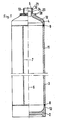
- Figure 1 shows a longitudinal section (right half) and a plan view (left half) of a pressure vessel according to the invention.
- the pressure vessel 1 is a multi-part welded design made of corrosion-resistant stainless steel, which is particularly suitable for storing and removing noble, special gases or gas mixtures of high purity and consists of a base part 2 welded to one another, a cylindrical jacket 3 and a head part 4 with a molded part Neck 5 is made.
- the cylindrical jacket 3 is a longitudinally welded tube with a weld seam 7 running parallel to the container axis 6, but a seamless tube can also be used for this.
- Bottom 2 and head part 4 are connected to the cylindrical jacket 3 by means of circular welds 8, 9, the three parts 2, 3, 4 of the pressure vessel 1 having been subjected to a heat treatment after being shaped, before being welded to one another.
- the entire inner surface 10, 11, 12 of the pressure vessel 1, including the neck 5, is electropolished after the welding in order to reduce the roughness to a great extent and to reduce the remaining stresses.
- the inner surfaces 10, 11, 12 can also be electropolished before welding, with post-treatment of the circular weld seams 8, 9 being necessary, depending on the requirements.
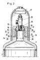
- FIG. 2 the connection according to the invention is shown on an enlarged scale in longitudinal section.
- An adapter piece 14 which is designed as an essentially cylindrical hollow body, is connected to the neck 5 of the pressure vessel 1 by means of a union nut 15.
- the left half of the adapter piece 14 graphically represents the variant that the adapter piece 14 forms an integral unit with the connecting body 26 of the valve 25.
- the adapter piece 14 has Region of the container-side end on an outwardly extending collar 16 which, like the cylindrical part 17, is surrounded by the union nut 15.
- Connected to the bore part 18 of the union nut 15 is a part 19 which is provided with an internal thread and which is screwed to a neck 5 which carries an external thread 20 (FIG. 1).
- a recess 22 is provided, into which a corrosion-resistant metallic seal 32 is arranged.
- the seal 32 is pressed onto the end face 21 by the rotation of the union nut 15.
- a central shoulder 23 is provided at the end on the container side, which is slightly smaller in diameter than the bore 13 of the neck 5. So that during the rotation of the union nut 15 no abrasion of the seal 32 producing rotation of the adapter piece 14 is possible , a cross-sectional shape 24 deviating from the circular shape is provided at the valve-side end.
- two opposing secants are produced mechanically in a simple manner in order to be able to hold an open-end wrench or a comparable tool.
- Other cross-sectional profiles that enable the adapter piece 14 to be held may just as well be.
- Another possibility is to make two axially extending, mutually opposite blind holes in this valve-side end in order to insert a hook wrench.
- a standard valve 25 is screwed into the adapter piece 14 with its connecting body 26 carrying a thread 33.
- the adapter piece 14 can be welded to the connector body 26 and then electropolished without the sensitive mechanical valve parts (not shown here).
- the known protective cap 27 is screwed onto an element 28 of the head part 4 which has an external thread. This element 28 can also be a ring shrunk onto the head part 4 (not shown here).
Landscapes
- Engineering & Computer Science (AREA)
- Mechanical Engineering (AREA)
- General Engineering & Computer Science (AREA)
- Filling Or Discharging Of Gas Storage Vessels (AREA)
- Projection Apparatus (AREA)
- Testing, Inspecting, Measuring Of Stereoscopic Televisions And Televisions (AREA)
- Stereoscopic And Panoramic Photography (AREA)
Description
- Die Erfindung betrifft einen Druckbehälter zur Speicherung und Entnahme von Edelgas-, Spezialgas oder Gasgemischen hoher Reinheit gemäß dem Gattungsbegriff des Hauptanspruches.
- Für die Fertigung u. a. in der Elektronikindustrie werden Gase hoher Reinheit benötigt. Bei der Speicherung und dem Transport derartiger Gase in üblichen Stahlflaschen kommt es zu Verunreinigungen und zur Beeinträchtigung der Gemischkonstanz, die die Verwendungsmöglichkeit der Gase beeinträchtigen. Diese Bedingungen gelten insbesondere für korrosive, giftige und brennbare Gase, die z. B. bei der Halbleitertechnik benötigt werden.
- Bekannt ist es, daß die Oberflächenbeschaffenheit und die Sauberkeit der Innenoberfläche des Druckbehälters auf die Reinheit und die Gemischstabilität der Gase großen Einfluß hat. Darüber hinaus ist aber auch das verwendete Material von Einfluß. Andererseits wird aus wirtschaftlichen Gründen des Transportes und der Lagerung verlangt, daß die Gase unter hohem Druck gehalten werden können. Dies erfordert auch ein hochfestes Druckbehältermaterial. Die Festigkeitsanforderungen erfüllt die bekannte Stahlflasche aus unlegiertem oder niedrig legiertem Stahl zwar bestens; sie wird nach dem stand der Technik aber dennoch nicht im Hinblick auf die Reinheits- und Korrosionsanforderung für geeignet angesehen.
- Man hat bereits erkannt, daß die Gasverunreinigung um so geringer ist, je kleiner die Oberflächenrauheit der Druckbehälterinnenwand ist. Zur Erzeugung einer möglichst glatten Innenoberfläche ist in der vorbekannten DE-AS 23 64 377 vorgeschlagen worden, eine Flasche aus ferritisch-perlitischem Stahl innen galvanisch zu verzinnen oder zu verzinken. An anderer Stelle wird vorgeschlagen, die Innenoberfläche mit Quarzkugeln zu strahlen und chemisch oder mit Ultraschall zu reinigen.
- Aus der DE-A-36 14 290 ist ein Druckgasbehälter aus einer austenitischen Stahllegierung bekannt, in dem ultrareine Gase gespeichert werden können. Hierzu wird als Behälterwerkstoff ein metastabiler CrNi-Stahl mit definierten Gehalten an Ti, Nb, Ni und C verwendet. Die Rohbehälter können elektrolytisch poliert sein und werden durch Aufbringen von Innendruck bei Temperaturen unterhalb der Martensitumwandlung plastisch verformt und dadurch verfestigt.
- Ein weiterer Druckbehälter zur Speicherung und Entnahme von Gasen ist aus der US-A-33 84 133 bekannt. Hierbei ist ein Adapterstück für das Ventil in den Kopfteil eingeschraubt. Der die schutzkappe haltende äußere Gewindeabschnitt ist Bestandteil des Adapters, so daß die Schutzkappe beim Umfallen der Flasche leicht das empfindliche Dichtsystem des Ventilanschlusses beschädigen kann.
- Aufgabe der Erfindung ist es, einen Druckbehälter mit einem Anschluß mit verbesserten Eigenschaften für die Speicherung und Entnahme von Edelgasen, Spezialgasen und Gasgemischen hoher Reinheit zu schaffen, um eine Verunreinigung und/oder eine Beeinträchtigung der Gemischkonstanz der Gase beim Lagern zu vermeiden. Der Druckbehälter sowie der Anschluß sollen überdies für Gasdrücke bis ca. 200 bar geeignet und kostengünstig herzustellen sein.
- Die Lösung der Aufgabe ist ein Druckbehälter mit den kennzeichnenden Merkmalen des Hauptanspruches.
- Das Material des Druckbehälters ist gegen alle in Betracht kommenden Gase und Gasgemische in hohem Maße chemisch beständig. Es hat überdies die Eigenschaft, daß es sich galvanisch hochglanzpolieren (elektrochemisches Polieren) läßt, wodurch die aktive Oberfläche eingeebnet und gegenüber dem unpolierten Zustand erheblich verkleinert wird. Dadurch wird der Absorptionseffekt der Gase auf die Behälterinnenwand sowie die Abgabe von Partikeln stark vermindert. Außerdem ist die Innenoberfläche nach dem Elektropolieren frei von mechanischen Restspannungen, die durch den Herstellungsprozeß entstanden sind, was die Sorptionsneigung des Behältermaterials vermindert.
- Für die vorgesehenen Zwecke werden die Druckbehälter, insbesondere Gasflaschen, die hauptsächlich die üblichen Einheitsabmessungen haben, im Tauchverfahren poliert. Für größere Abmessungen kann vorgesehen sein, daß der Druckbehälter selbst das Gefäß zur Aufnahme des beim Elektropolieren benötigten Elektrolyten ist. Auf jeden Fall wird eine kathodische Gleichstromelektrode von ausreichender Länge in den Druckbehälter eingeführt, damit auch der Boden und das Kopfteil, sowie im Falle des mehrteilig geschweißten Druckbehälters die Schweiß- oder Lötnähte innen poliert werden. Ein derartiger Druckbehälter, insbesondere mit einem Nickelgehalt an der oberen Grenze wird für höhere Drücke in dem angegebenen Bereich ziemlich schwer und damit teuer sein, da das Material in geglühtem Zustand nur mässige Festigkeitseigenschaften besitzt. Es werden deswegen außerdem die Maßnahmen nach den Unteransprüchen vorgeschlagen. Eine der Möglichkeiten ist, mit einem reduzierten Nickelgehalt ein ferritisch-austenitisches Mischgefüge zu erzeugen, das mit geringem Molybdänzusatz die Streckgrenze des Materials um etwa den Faktor 2,5 anhebt gegenüber dem üblichen austenitischen Material.
- Eine andere Maßnahme zur Gewichtsreduzierung ist im Falle des mehrteilig geschweißten Druckbehälters die zusätzliche Kaltverfestigung des zylindrischen Mantels des Druckbehälters. Dazu wird ein nahtloses oder geschweißtes Rohr bis in die Nähe des Anschlußbereiches um mindestens 10 bis 35 % in der Wanddicke abgestreckt, bevor es mit dem Kopf- und Bodenteil verschweißt wird. Im Anschlußbereich muß die ursprüngliche Wanddicke bestehen bleiben, da ein Anlassen des kaltverfestigten Bereiches durch das Verbindungsschweißen bzw. Löten die angestrebte Festigkeitserhöhung zunichte machen würde. Wegen der bei einigen Typen großen Länge des Druckbehälters im Verhältnis zu seinem Durchmesser wirkt sich das Abstrecken zum Beispiel auf 75 % der ursprünglichen Wanddicke erheblich gewichtsmindernd aus.
- Eine weitere Maßnahme in Hinblick auf Gewichtseinsparung ist die Verstärkung des zylindrischen Teiles des Druckbehälters mit einer spannungslos oder unter Zug aufgebrachten von einem Kunststoff umhüllte Faserwicklung. Über diese Wicklung wird je nach Dicke und Vorspannung ein Teil der durch den Innendruck verursachten Spannung abgebaut, so daß die Wanddicke des metallischen Körpers im zylindrischen Bereich reduziert werden kann. Der Effekt der Gewichtseinsparung wird noch verstärkt, wenn der Vorschlag einer Faserwicklung mit einem kaltverfestigten zylindrischen Mantel kombiniert wird.
- Der Druckbehälter kann in einer nahtlos einteiligen oder in einer mehrteilig geschweißten Ausführung hergestellt werden.
- Der Vorteil der mehrteilig geschweißten Ausführung liegt darin, daß die einzelnen Teile leicht bearbeitet werden können, so daß die Innenoberflächen vor dem Elektropolieren entsprechend geglättet werden können. Alternativ ist es auch möglich, die einzelnen Teile des Druckbehälters vor dem Zusammenfügen zu elektropolieren und, falls erforderlich, nur die Nahtbereiche einer Nachbehandlung zu unterziehen. Die beim Warmumformen des Kopf- bzw. Bodenteiles einer einteiligen Flasche entstehenden, meistens kaum zu vermeidenden, kleinen Oberflächenanrisse können durch das Elektropolieren nur mit großem Aufwand und nur teilweise beseitigt werden. Der Effekt des Elektropolierens ist um so größer und der dafür erforderliche Aufwand um so geringer, je glatter die Oberfläche auf mechanischem Wege vorbereitet ist. Eine solche glatte Oberfläche ist auch über den Weg eines durch Kaltumformung hergestellten einteiligen Druckbehälters erreichbar.
- Der Aufwand zur Verminderung der Rauheit, der in bezug auf die Innenoberflächen des Druckbehälters getrieben wird, muß auch den Anschluß mit einschließen, da ansonsten das Ziel einer deutlichen Partikelreduzierung für das Gesamtsystem nicht gewährleistet werden kann. Dazu ist es erforderlich, daß zum einen der Halsbereich des Druckbehälters elektropolierbar sein muß und die Verbindung des Ventils mit dem Druckbehälter zu keinem Materialabrieb führen darf. Zur Lösung dieses Problems wird für große Druckbehälter vorgeschlagen, die Bohrung im Halsbereich so groß wie möglich, d. h. gleich größer 40 mm Durchmesser zu wählen und statt des üblichen genormten kegeligen Innengewindes im Hals ein drehsicherbares Adapterstück anzuordnen, daß mit Hilfe einer Überwurfmutter mit dem Hals verbunden ist. Zwischen Adapterstück und Stirnfläche des Halses wird eine korrosionsbeständige metallische Dichtung eingesetzt. Diese Anordnung hat den Vorteil, daß durch das drehgesicherte Adapterstück die Dichtung nur auf Druck beansprucht und damit kein Abrieb erzeugt wird. Für die Drehsicherung des Adapterstückes gibt es mehrere Möglichkeiten, z. B. ein geradzahliges Mehrkantenprofil in Form von Sekanten zur Aufnahme eines Maulschlüssels oder eines entsprechenden Werkzeuges am ventilseitigen Ende des Adapterstückes anzuordnen oder zwei in axialer Richtung sich erstreckende Sacklochbohrungen vorzusehen, um einen Hakenschlüssel oder ein entsprechendes Werkzeug anzusetzen.
- Die Verbindung des Adapterstückes mit dem Ventil kann in der Weise erfolgen, daß das Adapterstück mit dem Anschlußkörper des Ventils verschweißt oder gelötet wird und anschließend die gesamte Vorrichtung im Tauchverfahren elektropoliert wird. Eine Abwandlung dieser Verbindung besteht darin, den Anschlußkörper des Ventils in der Bohrung des Adapterstückes anzuordnen und an der Übergangsstelle außen und/oder innen eine Naht vorzusehen. Eine weitere Möglichkeit sieht vor, daß das Adapterstück im Bohrungsbereich mit einem genormten Innengewinde versehen wird und nach dem Aufschrauben des Anschlußkörpers des Ventils die gesamte Vorrichtung ebenfalls elektropoliert wird. Zur weiteren Absicherung kann auch eine dichtende Naht an der Übergangsstelle außen und/oder innen angebracht werden. Die Schraubverbindung ohne eine dichtende Naht hätte den Vorteil, daß das Ventil zu jeder Zeit auswechselbar ist bei Wiederverwendbarkeit des Adapterstückes. Bildet man das Adapterstück als integrale Einheit des Anschlußkörpers des Ventils aus, dann kann diese Einheit nach dem Elektropolieren direkt und ohne eine weitere Verbindungsnaht mit dem Hals des Druckbehälters verschraubt werden. Ebenso ist es möglich, das Adapterstück und den Hals als integrale Einheit auszubilden und den Ventilkörper mit einem entsprechenden Kragen am Hals festzuschrauben. Alternativ zu dem beschriebenen Ausführungsbeispiel gibt es auch die Möglichkeit, das Adapterstück direkt über eine Naht mit dem Hals des Druckbehälters zu verbinden. Bei dieser Art der Ausführung würde der Dichtring und die Überwurfmutter entfallen. Die Verbindungsmöglichkeiten des Adapterstückes mit dem Ventil entsprechen denen, wie sie bereits vorher für das andere Ausführungsbeispiel erläutert worden sind.
- Die Schutzkappe wird an einem ein Außengewinde tragenden Abschnitt des Kopfteiles aufgeschraubt, wobei dieser Abschnitt integraler Teil des Kopfteiles sein kann oder als aufgeschrumpfter Ring ausgebildet ist. Durch diese Trennung der Befestigung der Schutzkappe und des Ventils wird sichergestellt, daß bei einem versehentlichen Umfallen der Flasche oder bei einer nicht beabsichtigten Schlagbeanspruchung von außen auf die Schutzkappe der Ventilanschluß nicht in Mitleidenschaft gezogen wird.
- Das Material, das für die Herstellung des Adapterstückes, der Überwurfmutter und des Ventilkörpers verwendet wird, muß nicht identisch mit dem des Druckbehälters sein, mit der Ausnahme, daß daß Adapterstück integraler Bestandteil des Halses ist. Es kann im Hinblick auf eine gute Zerspanbarkeit und Formgebungsmöglichkeit entsprechend gewählt werden, muß aber die Forderungen der Korrosionsbeständigkeit und Festigkeit ebenfalls erfüllen.
- Die Erfindung wird an einem schematisch dargestellten Ausführungsbeispiel näher erläutert.
- Es zeigt
- Figur 1
- einen Längsschnitt und eine Draufsicht durch einen mehrteilig geschweißten Druckbehälter ohne Ventil und Schutzkappe
- Figur 2
- einen Längsschnitt des erfindungsgemäßen Anschlusses
- Figur 3
- wie Fig. 2, jedoch mit einem angeschweißten Adapterstück
- Figur 1 zeigt einen Längsschnitt (rechte Hälfte) und eine Draufsicht (linke Hälfte) eines erfindungsgemäßen Druckbehälters. Der Druckbehälter 1 ist in diesem Ausführungsbeispiel eine mehrteilige geschweißte Ausführung aus korrosionsbeständigem Edelstahl, der besonders geeignet ist zur Speicherung und Entnahme von Edel-, Spezialgasen oder Gasemischen hoher Reinheit und aus einem miteinander verschweißten Bodenteil 2, einem zylindrischen Mantel 3 und einem Kopfteil 4 mit angeformtem Hals 5 besteht. Der zylindrische Mantel 3 ist in diesem Ausführungsbeispiel ein längsnahtgeschweißtes Rohr mit einer parallel zur Behälterachse 6 verlaufenden Schweißnaht 7, es kann aber ebenso dafür ein nahtloses Rohr verwendet werden. Boden 2- und Kopfteil 4 sind über Rundschweißnähte 8, 9 mit dem zylindrischen Mantel 3 verbunden, wobei die drei Teile 2,3,4 des Druckbehälters 1 nach ihrer Formgebung einer Wärmebehandlungunterzogen worden sind, bevor sie miteinander verschweißt wurden. Die gesamte Innenoberfläche 10,11,12 des Druckbehälters 1 einschließlich des Halses 5 wird nach dem Verschweißen elektropoliert, um die Rauheit in starkem Maße zu vermindern und die noch verbliebenen Restspannungen abzubauen. Zur Durchführung des Verfahrens und im Hinblick auf die Revision bzw. für eine spätere Nachrevision ist es erforderlich, den Durchgang (hier dargestellt durch den Pfeil 13) im Hals 5 möglichst groß zu wählen und ihn konstruktiv glatt ohen störende Kanten und Vorsprünge zu gestalten. Das Elektropolieren der Innenoberflächen 10,11,12 kann auch vor dem Verschweißen erfolgen, wobei je nach Anforderung eine Nachbehandlung der Rundschweißnähte 8,9 erforderlich sein kann.
- In Figur 2 wird in einem vergrößerten Maßstab im Längsschnitt der erfindungsgemäße Anschluß dargestellt. Ein Adapterstück 14, das als ein im wesentlichen zylinderförmiger Hohlkörper ausgebildet ist, ist mit Hilfe einer Überwurfmutter 15 mit dem Hals 5 des Druckbehälters 1 verbunden. Dabei stellt die linke Hälfte des Adapterstückes 14 zeichnerisch die Variante dar, daß das Adapterstück 14 mit dem Anschlußkörper 26 des Ventils 25 eine integrale Einheit bildet. Das Adapterstück 14 weist im Bereich des behälterseitigen Endes einen nach außen sich erstreckenden Kragen 16 auf, der ebenso wie der zylindrische Teil 17 von der Überwurfmutter 15 umfaßt wird. An dem Bohrungsteil 18 der Überwurfmutter 15 schließt sich ein mit einem Innengewinde versehener Teil 19 an, der mit einem ein Außengewinde 20 (Figur 1) tragenden Hals 5 verschraubt ist. In einer des Stirnfläche 21 des Halses 5 zugewandten Kragenseite des Adapterstückes 14 ist eine Ausnehmung 22 vorgesehen, in die eine korrosionsbeständige metallische Dichtung 32 angeordnet wird. Durch die Drehung der Überwurfmutter 15 wird die Dichtung 32 auf die Stirnfläche 21 gepreßt. Zur sicheren Führung des Adapterstückes 14 ist am behälterseitigen Ende ein zentrischer Absatz 23 vorgesehen, der im Durchmesser etwas kleiner ist als die Bohrung 13 des Halses 5. Damit während der Drehung der Überwurfmutter 15 keine einen Abrieb der Dichtung 32 erzeugende Drehung des Adapterstückes 14 möglich ist, ist am ventilseitigen Ende eine von der Kreisform abweichende Querschnittsform 24 vorgesehen. In diesem Ausführungsbeispiel werden in einfacher Weise zwei sich gegenüberliegende Sekanten mechanisch hergestellt, um einen Maulschlüssel oder ein vergleichbares Werkzeug aufnehmen zu können. Ebenso gut können es andere Querschnittsprofile sein, die ein Halten des Adapterstückes 14 ermöglichen. Eine andere Möglichkeit besteht darin, an diesem ventilseitigen Ende zwei in axialer Richtung sich erstreckende, einander gegenüberliegende Sacklochbohrungen anzubringen, um einen Hakenschlüssel hineinzustecken.
- Bei diesem Ausführungsbeispiel wird ein Standard-Ventil 25 mit seinem ein Gewinde 33 tragenden Anschlußkörper 26 in das Adapterstück 14 hineingeschraubt. Alternativ kann das Adapterstück 14 mit dem Anschlußkörper 26 verschweißt werden und danach ohne die empfindlichen mechanischen Ventilteile (hier nicht dargestellt), elektropoliert werden. Die bekannte Schutzkappe 27 wird auf einem ein Außengewinde aufweisendes Element 28 des Kopfteiles 4 aufgeschraubt. Dieses Element 28 kann auch ein auf das Kopfteil 4 aufgeschrumpfter Ring sein (hier nicht dargestellt).
- Durch diese Trennung der Befestigung der Schutzkappe 27 und des Ventils 25 wird sichergestellt, daß unerwünschte Einwirkungen auf die Schutzkappe 27 nicht auf das Ventil 25 und auf die Dichtung 32 übertragen werden können.
Claims (16)
- Edelstahlflasche (1) zur Speicherung und Entnahme von Edel-, Spezialgasen oder Gasgemischen hoher Reinheit, bestehend aus einem Boden (2), einem Mantel (3) und einem Kopfteil (4), deren Innenoberflächen elektrochemisch poliert sind,
dadurch gekennzeichnet,
daßa) der korrosionsbeständige Edelstahl mit Massegehalten bis zu 0,06 % Kohlenstoff, 1,5 bis 6,0 % Mangan, 0,3 bis 1,0 % Silizium, 16 bis 25 % Chrom, 4 bis 18 % Nickel, gegebenfalls bis zu 4 % Molybdän, gegebenenfalls bis zu 0,35 % N₂, gegebenenfalls bis zu 0,25 % Nb, Rest Eisen mit Verunreinigungen bis zur üblichen Untergrenze enthält undb) der Druckbehälter (1) mehrteilig ist und der Boden (2), der Mantel (3) und das Kopfteil (4) nach der Formgebung geglüht und dann durch eine Schweiß- der Lötnaht miteinander verbunden sind undc) der Anschluß ein mit dem Hals (5) lösbar verbundenes Adapterstück (14), an dem das Ventil (25) befestigbar ist und am übergang vom Kopfteil (4) zum Hals (5) ein ein Außengewinde (20) tragender Abschnitt (28) zur Aufnahme der Schutzkappe und der Hals (5) einen ein Außengewinde tragenden Abschnitt (34) aufweist. - Edelstahlflasche nach Anspruch 1,
dadurch gekennzeichnet,
daß der Edelstahl ferritisch-austenitisch ist und 4 - 9 % Ni und 0,5 - 3 % Mo, 0,20 - 0,35 % N₂ enthält. - Edelstahlflasche nach Anspruch 1,
dadurch gekennzeichnet,
daß für den Mantel (3) ein nahtloses oder geschweißtes Rohr verwendet wird, das bis in die Nähe des Anschlußbereiches durch Kaltverformung um mindestens 10 bis 35 % in der Wanddicke abgestreckt ist, bevor es mit dem Kopf (4) und dem Bodenteil (2) verbunden wird. - Edelstahlflasche nach den Ansprüchen 1 - 3,
dadurch gekennzeichnet,
daß der zylindrische Teil des Druckbehälters (1) eine außen aufgebrachte einlagige oder mehrlagige Faserwicklung aufweist, deren unter Zug aufgewickelte Fasern mit Kunststoff umhüllt sind. - Edelstahlflasche nach Anspruch 1,
dadurch gekennzeichnet,
daß das Adapterstück (14) drehsicherbar ausgebildet und mit dem Hals (5) durch eine ihn und den mit einen Außengewinde versehenen Abschnitt (34) des Halses (5) umfassende überwurfmutter (15), die einen Bohrungs (18)- und einen Innengewindeabschnitt (19) aufweist lösbar verbunden und auf der Stirnfläche (21) des Halses (5) eine Dichtung (32) angeordnet ist. - Edelstahlflasche nach Anspruch 5,
dadurch gekennzeichnet,
daß das Adapterstück (14) im Bereich des behälterseitigen Endes einen nach außen sich erstreckenden zylindrischen Kragen (16) und im Bereich des ventilseitigen Endes eine von der Kreisform abweichende Querschnittsform (24) aufweist. - Edelstahlflasche nach Anspruch 6,
dadurch gekennzeichnet,
daß das ventilseitige Ende des Adapterstückes (14) ein geradzahliges Mehrkantprofil (24) in Form von Sekanten zur Aufnahme eines Maulschlüssels oder eines vergleichbaren Werkzeuges aufweist. - Edelstahlflasche nach Anspruch 5,
dadurch gekennzeichnet,
daß das ventilseitige Ende des Adapterstückes (14) zwei in axialer Richtung sich erstreckende einander gegenüberstehende Sacklochbohrungen zur Aufnahme eines Hakenschlüssels aufweist. - Edelstahlflasche nach den Ansprüchen 5 und 6,
dadurch gekennzeichnet,
daß das Adapterstück (14) am behälterseitigen Ende mit einem der Bohrung (13) des Halses (5) angepassten Zentrierabsatz (23) versehen ist und im Kragen (16) des Adapterstückes (14) auf der der Stirnfläche (21) des Halses (5) zugewandten Seite eine ringförmige Ausnehmung (22) zur Aufnahme der Dichtung (32) angeordnet ist. - Edelstahlflasche nach den Ansprüchen 5 und 6,
dadurch gekennzeichnet,
daß in dar Bohrung (13) des Halses (5) ein dem Außendurchmesser des Adapterstückes (14) angepaßter Zentrierabsatz vorhanden und in diesem Zentrierabsatz eine ringförmige Ausnehmung zur Aufnahme der Dichtung (32) angeordnet ist. - Edelstahlflasche nach Anspruch 5,
dadurch gekennzeichnet,
daß die Bohrung des Adapterstückes (14) mit der des Ventilkörpers (26) fluchtet und die Verbindungsstelle eine Schweiß- oder Lötnaht aufweist. - Edelstahlflasche nach Anspruch 5,
dadurch gekennzeichnet,
daß dar Ventilkörper (26) in der Bohrung des Adapterstückes (14) angeordnet ist und die übergangsstelle Adapterstück (14)/Ventilkörper (26) außen und/oder innen eine Naht aufweist. - Edelstahlflasche nach Anspruch 5,
dadurch gekennzeichnet,
daß das Adapterstück (14) mit dem Ventilkörper (26) eine integrale Einheit bildet. - Edelstahlflasche nach Anspruch 5,
dadurch gekennzeichnet,
daß zur Aufnahme eines Ventils (26) das Adapterstück (14) im Bohrungsbereich ein Innengewinde (29) aufweist. - Edelstahlflasche nach Anspruch 14,
dadurch gekennzeichnet,
daß nach dem Einschrauben des Ventils (25) die übergangsstelle Adapterstück(14)/Ventilkörper (26) außen und/oder innen eine Dichtnaht aufweist. - Edelstahlflasche nach Anspruch 5,
dadurch gekennzeichnet,
daß die Dichtung (32) ein aus korrosionsbeständigem Material hergestellter metallischer Dichtring ist.
Priority Applications (1)
| Application Number | Priority Date | Filing Date | Title |
|---|---|---|---|
| AT88730233T ATE89904T1 (de) | 1987-10-26 | 1988-10-25 | Druckbehaelter zur speicherung von gasen hoher reinheit. |
Applications Claiming Priority (2)
| Application Number | Priority Date | Filing Date | Title |
|---|---|---|---|
| DE3736579 | 1987-10-26 | ||
| DE3736579A DE3736579C3 (de) | 1987-10-26 | 1987-10-26 | Druckbehälter zur Speicherung von Gasen hoher Reinheit |
Publications (3)
| Publication Number | Publication Date |
|---|---|
| EP0314609A2 EP0314609A2 (de) | 1989-05-03 |
| EP0314609A3 EP0314609A3 (en) | 1989-11-29 |
| EP0314609B1 true EP0314609B1 (de) | 1993-05-26 |
Family
ID=6339296
Family Applications (1)
| Application Number | Title | Priority Date | Filing Date |
|---|---|---|---|
| EP88730233A Expired - Lifetime EP0314609B1 (de) | 1987-10-26 | 1988-10-25 | Druckbehälter zur Speicherung von Gasen hoher Reinheit |
Country Status (5)
| Country | Link |
|---|---|
| US (1) | US4884708A (de) |
| EP (1) | EP0314609B1 (de) |
| AT (1) | ATE89904T1 (de) |
| DE (1) | DE3736579C3 (de) |
| ES (1) | ES2041333T3 (de) |
Cited By (1)
| Publication number | Priority date | Publication date | Assignee | Title |
|---|---|---|---|---|
| IT202100009098A1 (it) * | 2021-04-12 | 2022-10-12 | Carbon Cylinder S R L | Bocchelo per bombole ad alta pressione |
Families Citing this family (27)
| Publication number | Priority date | Publication date | Assignee | Title |
|---|---|---|---|---|
| SE8804247L (sv) * | 1988-11-24 | 1990-05-25 | Sandvik Ab | Koppling foer gasflaska flaska samt metod att tillverka flaskan |
| US5027952A (en) * | 1989-02-28 | 1991-07-02 | Nch Corporation | Plastic bottle for acid drain opening system |
| US5593649A (en) * | 1989-03-08 | 1997-01-14 | Abtox, Inc. | Canister with plasma gas mixture for sterilizer |
| US5650693A (en) * | 1989-03-08 | 1997-07-22 | Abtox, Inc. | Plasma sterilizer apparatus using a non-flammable mixture of hydrogen and oxygen |
| US5058758A (en) * | 1991-01-07 | 1991-10-22 | Suddeth Bucky D | Compressed gas cylinder valve and gauge protector |
| DE19522197A1 (de) * | 1995-06-21 | 1997-01-02 | Bartels & Rieger | Hochdruckbehälter, insbesondere als Druckgasflasche für Atemschutz- oder Tauchgeräte, mit einem in den Flaschenhals einschraubbaren Regel- bzw. Absperrventil |
| KR20000006891U (ko) * | 1998-09-23 | 2000-04-25 | 민병일 | 유아용 알루미늄 젖병의 용량 확인장치 |
| DE19924098A1 (de) * | 1999-05-26 | 2000-12-07 | Boehringer Ingelheim Pharma | Edelstahlkanister für treibgasbetriebene Dosieraerosole |
| US6739333B1 (en) | 1999-05-26 | 2004-05-25 | Boehringer Ingelheim Pharma Kg | Stainless steel canister for propellant-driven metering aerosols |
| DE19955204B4 (de) * | 1999-11-17 | 2011-01-20 | Air Liquide Deutschland Gmbh | Verfahren und Vorrichtung für die Kraftstoffversorgung eines flüssiggasbetriebenen Fahrzeugs |
| RU2178861C2 (ru) * | 2000-04-19 | 2002-01-27 | Федеральное государственное унитарное предприятие "Производственное объединение "Баррикады" | Способ изготовления металлического баллона высокого давления |
| RU2183787C2 (ru) * | 2000-09-01 | 2002-06-20 | Государственный космический научно-производственный центр им. М.В. Хруничева | Горловина заправочная |
| GB0031176D0 (en) * | 2000-12-21 | 2001-01-31 | Glaxo Group Ltd | Medicament dispenser |
| US8158057B2 (en) | 2005-06-15 | 2012-04-17 | Ati Properties, Inc. | Interconnects for solid oxide fuel cells and ferritic stainless steels adapted for use with solid oxide fuel cells |
| US7981561B2 (en) | 2005-06-15 | 2011-07-19 | Ati Properties, Inc. | Interconnects for solid oxide fuel cells and ferritic stainless steels adapted for use with solid oxide fuel cells |
| US7842434B2 (en) | 2005-06-15 | 2010-11-30 | Ati Properties, Inc. | Interconnects for solid oxide fuel cells and ferritic stainless steels adapted for use with solid oxide fuel cells |
| TWI232281B (en) * | 2002-08-16 | 2005-05-11 | Toppoly Optoelectronics Corp | A backlight device of a LCD display |
| US6886711B2 (en) * | 2002-08-22 | 2005-05-03 | Samtech Corporation | High-pressure tank and method for fabricating the same |
| US8518234B2 (en) * | 2003-09-03 | 2013-08-27 | Ati Properties, Inc. | Oxidation resistant ferritic stainless steels |
| US20070284395A1 (en) * | 2006-06-09 | 2007-12-13 | Scott Specialty Gases, Inc. | Container and method for maintaining stability of gas mixtures |
| DE102008024292A1 (de) * | 2008-05-20 | 2009-11-26 | Bayerische Motoren Werke Aktiengesellschaft | Composite-Druckgasbehälter |
| US9080725B2 (en) * | 2013-09-19 | 2015-07-14 | Pa.E Machinery Industrial Co., Ltd. | Pressure vessel |
| JP6307900B2 (ja) * | 2014-01-29 | 2018-04-11 | 日本ゼオン株式会社 | フッ素化炭化水素化合物充填ガス容器 |
| US9683700B2 (en) * | 2014-05-20 | 2017-06-20 | Steelhead Composites, Llc. | Metallic liner pressure vessel comprising polar boss |
| MA43446B1 (fr) | 2018-10-01 | 2020-07-29 | Imaplast | Collet protecteur de valve pour bouteilles gpl |
| FR3096432B1 (fr) * | 2019-05-24 | 2022-12-23 | Gaztransport Et Technigaz | Membrane étanche pour Cuve de Stockage |
| AT525931B1 (de) * | 2022-02-15 | 2023-11-15 | Gs Gruber Schmidt Gmbh | Vorrichtung zur Speicherung von Gasen, Dämpfen und Flüssigkeiten in Kartuschen |
Family Cites Families (30)
| Publication number | Priority date | Publication date | Assignee | Title |
|---|---|---|---|---|
| BE356964A (de) * | 1928-01-09 | |||
| US2118388A (en) * | 1936-06-29 | 1938-05-24 | Smith Corp A O | Method of making a welded spherical vessel |
| US2361318A (en) * | 1938-11-21 | 1944-10-24 | Union Metal Mfg Co | Tube product |
| GB730271A (en) * | 1943-01-22 | 1955-05-18 | Homer Farnum Priest | Apparatus for the storage of fluorine |
| US2613462A (en) * | 1948-04-06 | 1952-10-14 | Scaife Company | Pressure vessel |
| DE834859C (de) * | 1949-08-27 | 1952-03-24 | Ruhrchemie Ag | Gewindehalsring fuer Gasflaschen |
| US2661113A (en) * | 1951-01-08 | 1953-12-01 | Ernest H Benson | High-pressure container with adapter for discharge apertures |
| US2685546A (en) * | 1952-01-05 | 1954-08-03 | Atomic Energy Commission | Method for reducing the permeability of alloys by hydrogen |
| US2679454A (en) * | 1952-02-08 | 1954-05-25 | Union Carbide & Carbon Corp | Article for low-temperature use |
| DE1093394B (de) * | 1956-08-16 | 1960-11-24 | Mannesmann Ag | Verfahren zum Herstellen von Walzerzeugnissen aus stabilaustenitischen Chrom-Nickel-Staehlen |
| DE1824737U (de) * | 1960-07-21 | 1961-01-12 | Mannesmann Ag | Unmagnetischer druckgasbehaelter. |
| US3152718A (en) * | 1962-03-08 | 1964-10-13 | Weatherhead Co | Cylinder boss |
| US3384133A (en) * | 1965-07-01 | 1968-05-21 | William E. Gordon | Arrangement for filling or refilling a dispenser |
| GB1159972A (en) * | 1965-09-24 | 1969-07-30 | English Electric Co Ltd | Improvements in or relating to Pressure Vessels |
| FR2082455A5 (de) * | 1970-03-17 | 1971-12-10 | Pingeot Bardin Ets | |
| US3815773A (en) * | 1971-05-17 | 1974-06-11 | Brunswick Corp | Cyclic pressure vessel |
| GB1388431A (en) * | 1972-03-06 | 1975-03-26 | Jackson R G | Process of working a metal tube |
| SE374559B (de) * | 1973-10-05 | 1975-03-10 | Avesta Jernverks Ab | |
| DE2364377C3 (de) * | 1973-12-22 | 1982-11-18 | Messer Griesheim Gmbh, 6000 Frankfurt | Stahlflasche zur Aufbewahrung von Gasgemischen |
| GB1495259A (en) * | 1974-11-15 | 1977-12-14 | Fulmer Res Inst Ltd | Gas containers |
| DE2528942A1 (de) * | 1975-06-28 | 1976-12-30 | Hoechst Ag | Verfahren zum zonenweisen elektropolieren der inneren oberflaeche grossraeumiger behaelter |
| DE2538585A1 (de) * | 1975-08-29 | 1977-03-03 | John F Jumer | Verfahren und vorrichtung zum polieren der innenflaeche eines laenglichen behaelters |
| JPS5343663A (en) * | 1976-10-04 | 1978-04-19 | Nippon Kokan Kk | Manufacturing process of good accurate form steel sections for low temperature |
| DE3002768C2 (de) * | 1980-01-26 | 1984-02-23 | Gesellschaft zur Wiederaufbereitung von Kernbrennstoffen mbH, 7514 Eggenstein-Leopoldshafen | Absperrventil für in der Tiefsee zu lagernde Gasflaschen |
| US4332331A (en) * | 1980-06-03 | 1982-06-01 | Fawley Norman | Rotatable valve protector for compressed gas cylinder |
| DE3103646C2 (de) * | 1981-02-04 | 1984-03-29 | Aluminium-Walzwerke Singen Gmbh, 7700 Singen | Druckbehälter zur Lagerung sowie zum Transport gasförmiger Strömungsmittel |
| DE3507263C2 (de) * | 1985-03-01 | 1987-01-02 | GOK Regler- und Armaturen GmbH & Co KG, 5200 Siegburg | Unter Behälterdruck austauschbares Sicherheitsventil |
| DE3610855A1 (de) * | 1985-03-01 | 1987-10-08 | Gok Gmbh & Co Kg | Unter behaelterdruck austauschbares sicherheitsventil |
| DE3614290A1 (de) * | 1986-04-26 | 1987-10-29 | Messer Griesheim Gmbh | Druckgasbehaelter aus einer austenitischen stahllegierung |
| DE3617092A1 (de) * | 1986-05-21 | 1987-11-26 | Poligrat Gmbh | Innenoberflaeche einer gasflasche und verfahren zu deren herstellung |
-
1987
- 1987-10-26 DE DE3736579A patent/DE3736579C3/de not_active Expired - Lifetime
-
1988
- 1988-10-19 US US07/259,999 patent/US4884708A/en not_active Expired - Fee Related
- 1988-10-25 AT AT88730233T patent/ATE89904T1/de not_active IP Right Cessation
- 1988-10-25 EP EP88730233A patent/EP0314609B1/de not_active Expired - Lifetime
- 1988-10-25 ES ES198888730233T patent/ES2041333T3/es not_active Expired - Lifetime
Cited By (2)
| Publication number | Priority date | Publication date | Assignee | Title |
|---|---|---|---|---|
| IT202100009098A1 (it) * | 2021-04-12 | 2022-10-12 | Carbon Cylinder S R L | Bocchelo per bombole ad alta pressione |
| WO2022218672A1 (en) * | 2021-04-12 | 2022-10-20 | Carbon Cylinder S.R.L. | Nozzle for high-pressure cylinders |
Also Published As
| Publication number | Publication date |
|---|---|
| ES2041333T3 (es) | 1993-11-16 |
| US4884708A (en) | 1989-12-05 |
| DE3736579C2 (de) | 1991-05-23 |
| ATE89904T1 (de) | 1993-06-15 |
| EP0314609A3 (en) | 1989-11-29 |
| DE3736579A1 (de) | 1989-05-03 |
| DE3736579C3 (de) | 1996-10-17 |
| EP0314609A2 (de) | 1989-05-03 |
Similar Documents
| Publication | Publication Date | Title |
|---|---|---|
| EP0314609B1 (de) | Druckbehälter zur Speicherung von Gasen hoher Reinheit | |
| DE19820054B4 (de) | Radbefestiger | |
| DE69616827T2 (de) | Gasbehälter | |
| DE10130681A1 (de) | Selbstbohrende Blindnietmutter | |
| DE19711844B4 (de) | Verfahren zum Herstellen eines Druckgasbehälters | |
| WO2014048652A1 (de) | Tankcontainer | |
| DE3727326C2 (de) | ||
| DD273613A1 (de) | Spundfass | |
| EP0698757A2 (de) | Verfahren zur Herstellung von Serienventilen | |
| EP0314608A2 (de) | Verfahren und Vorrichtung zur Herstellung von Skulpturen in reduzierter Grösse | |
| DE68912731T3 (de) | Kupplung für Gasbehälter. | |
| DE2306682A1 (de) | Aluminiumflaschen, insbesondere zur ueberdruckspeicherung von pb-gas, und verfahren zur homogenisierung und zum vergueten des flaschenstoffes | |
| WO2023117663A1 (de) | PUNKTSCHWEIß-ELEKTRODENKAPPE | |
| DE9413406U1 (de) | Schweißbolzen mit Hutmutter | |
| DE8408506U1 (de) | Druckgasflasche mit einem faserverstaerkten kunststoffmantel | |
| DE69026535T2 (de) | Stromzuführungswalze | |
| DE3815347C2 (de) | ||
| EP0210652B1 (de) | Schutzelement zum Abdecken von Teilbereichen an zu bearbeitenden Werkstücken | |
| EP0285686B1 (de) | Saugrohr für Vakuum-Druckgiessmaschine | |
| EP0000379B1 (de) | Verfahren zum Lichtbogenbolzenschweissen mit Hubzündung, sowie Schweisspistole zur Durchführung dieses Verfahrens. | |
| DE20119598U1 (de) | Schweißbolzen für eine elektrisch leitende Verbindung und elektrisch leitende Verbindung mit Schweißbolzen | |
| DD203805A5 (de) | Verfahren zur verhinderung des abbrands an einer stromleitenden elektrode fuer metallurgische oefen und elektrode | |
| DE3334661C2 (de) | ||
| AT392677B (de) | Zweiteiliges ventilsystem | |
| DE29615336U1 (de) | Steuerkopf-System |
Legal Events
| Date | Code | Title | Description |
|---|---|---|---|
| PUAI | Public reference made under article 153(3) epc to a published international application that has entered the european phase |
Free format text: ORIGINAL CODE: 0009012 |
|
| AK | Designated contracting states |
Kind code of ref document: A2 Designated state(s): AT ES FR GB IT SE |
|
| PUAL | Search report despatched |
Free format text: ORIGINAL CODE: 0009013 |
|
| AK | Designated contracting states |
Kind code of ref document: A3 Designated state(s): AT ES FR GB IT SE |
|
| 17P | Request for examination filed |
Effective date: 19891116 |
|
| 17Q | First examination report despatched |
Effective date: 19900503 |
|
| GRAA | (expected) grant |
Free format text: ORIGINAL CODE: 0009210 |
|
| AK | Designated contracting states |
Kind code of ref document: B1 Designated state(s): AT ES FR GB IT SE |
|
| REF | Corresponds to: |
Ref document number: 89904 Country of ref document: AT Date of ref document: 19930615 Kind code of ref document: T |
|
| ITF | It: translation for a ep patent filed | ||
| ET | Fr: translation filed | ||
| GBT | Gb: translation of ep patent filed (gb section 77(6)(a)/1977) |
Effective date: 19930621 |
|
| REG | Reference to a national code |
Ref country code: ES Ref legal event code: FG2A Ref document number: 2041333 Country of ref document: ES Kind code of ref document: T3 |
|
| PLBI | Opposition filed |
Free format text: ORIGINAL CODE: 0009260 |
|
| 26 | Opposition filed |
Opponent name: LINDE AKTIENGESELLSCHAFT, WIESBADEN Effective date: 19940228 |
|
| EAL | Se: european patent in force in sweden |
Ref document number: 88730233.9 |
|
| PLBN | Opposition rejected |
Free format text: ORIGINAL CODE: 0009273 |
|
| STAA | Information on the status of an ep patent application or granted ep patent |
Free format text: STATUS: OPPOSITION REJECTED |
|
| 27O | Opposition rejected |
Effective date: 19950302 |
|
| K1C3 | Correction of patent application (complete document) published |
Effective date: 19890503 |
|
| PGFP | Annual fee paid to national office [announced via postgrant information from national office to epo] |
Ref country code: AT Payment date: 19960923 Year of fee payment: 9 |
|
| PGFP | Annual fee paid to national office [announced via postgrant information from national office to epo] |
Ref country code: ES Payment date: 19961018 Year of fee payment: 9 |
|
| PGFP | Annual fee paid to national office [announced via postgrant information from national office to epo] |
Ref country code: GB Payment date: 19970915 Year of fee payment: 10 Ref country code: FR Payment date: 19970915 Year of fee payment: 10 |
|
| PGFP | Annual fee paid to national office [announced via postgrant information from national office to epo] |
Ref country code: SE Payment date: 19970925 Year of fee payment: 10 |
|
| PG25 | Lapsed in a contracting state [announced via postgrant information from national office to epo] |
Ref country code: AT Free format text: LAPSE BECAUSE OF NON-PAYMENT OF DUE FEES Effective date: 19971025 |
|
| PG25 | Lapsed in a contracting state [announced via postgrant information from national office to epo] |
Ref country code: ES Free format text: LAPSE BECAUSE OF THE APPLICANT RENOUNCES Effective date: 19971027 |
|
| PG25 | Lapsed in a contracting state [announced via postgrant information from national office to epo] |
Ref country code: GB Free format text: LAPSE BECAUSE OF NON-PAYMENT OF DUE FEES Effective date: 19981025 |
|
| PG25 | Lapsed in a contracting state [announced via postgrant information from national office to epo] |
Ref country code: SE Free format text: LAPSE BECAUSE OF NON-PAYMENT OF DUE FEES Effective date: 19981026 |
|
| GBPC | Gb: european patent ceased through non-payment of renewal fee |
Effective date: 19981025 |
|
| EUG | Se: european patent has lapsed |
Ref document number: 88730233.9 |
|
| PG25 | Lapsed in a contracting state [announced via postgrant information from national office to epo] |
Ref country code: FR Free format text: LAPSE BECAUSE OF NON-PAYMENT OF DUE FEES Effective date: 19990630 |
|
| REG | Reference to a national code |
Ref country code: FR Ref legal event code: ST |
|
| REG | Reference to a national code |
Ref country code: ES Ref legal event code: FD2A Effective date: 20001009 |
|
| PG25 | Lapsed in a contracting state [announced via postgrant information from national office to epo] |
Ref country code: IT Free format text: LAPSE BECAUSE OF NON-PAYMENT OF DUE FEES Effective date: 20051025 |