EP0314613A1 - Verfahren zur Herstellung eines Käfigankers mit kurzschliessendem Zwischenring - Google Patents
Verfahren zur Herstellung eines Käfigankers mit kurzschliessendem Zwischenring Download PDFInfo
- Publication number
- EP0314613A1 EP0314613A1 EP88810670A EP88810670A EP0314613A1 EP 0314613 A1 EP0314613 A1 EP 0314613A1 EP 88810670 A EP88810670 A EP 88810670A EP 88810670 A EP88810670 A EP 88810670A EP 0314613 A1 EP0314613 A1 EP 0314613A1
- Authority
- EP
- European Patent Office
- Prior art keywords
- sheets
- teeth
- rotor
- angle
- short
- Prior art date
- Legal status (The legal status is an assumption and is not a legal conclusion. Google has not performed a legal analysis and makes no representation as to the accuracy of the status listed.)
- Granted
Links
- 238000000034 method Methods 0.000 title claims abstract description 19
- 241000555745 Sciuridae Species 0.000 title claims abstract description 6
- 238000004519 manufacturing process Methods 0.000 title claims description 5
- 239000000696 magnetic material Substances 0.000 claims abstract description 5
- 238000005520 cutting process Methods 0.000 claims abstract description 4
- 239000004020 conductor Substances 0.000 claims description 4
- 230000000694 effects Effects 0.000 claims description 2
- 230000006698 induction Effects 0.000 claims description 2
- XEEYBQQBJWHFJM-UHFFFAOYSA-N Iron Chemical compound [Fe] XEEYBQQBJWHFJM-UHFFFAOYSA-N 0.000 description 4
- 229910052742 iron Inorganic materials 0.000 description 2
- 239000011159 matrix material Substances 0.000 description 2
- 229910052782 aluminium Inorganic materials 0.000 description 1
- XAGFODPZIPBFFR-UHFFFAOYSA-N aluminium Chemical compound [Al] XAGFODPZIPBFFR-UHFFFAOYSA-N 0.000 description 1
- 238000003475 lamination Methods 0.000 description 1
- 239000000463 material Substances 0.000 description 1
- 229910052751 metal Inorganic materials 0.000 description 1
- 239000002184 metal Substances 0.000 description 1
- 230000000750 progressive effect Effects 0.000 description 1
- 238000004080 punching Methods 0.000 description 1
Images


Classifications
-
- H—ELECTRICITY
- H02—GENERATION; CONVERSION OR DISTRIBUTION OF ELECTRIC POWER
- H02K—DYNAMO-ELECTRIC MACHINES
- H02K7/00—Arrangements for handling mechanical energy structurally associated with dynamo-electric machines, e.g. structural association with mechanical driving motors or auxiliary dynamo-electric machines
- H02K7/10—Structural association with clutches, brakes, gears, pulleys or mechanical starters
- H02K7/102—Structural association with clutches, brakes, gears, pulleys or mechanical starters with friction brakes
- H02K7/1021—Magnetically influenced friction brakes
- H02K7/1026—Magnetically influenced friction brakes using stray fields
- H02K7/1028—Magnetically influenced friction brakes using stray fields axially attracting the brake armature in the frontal area of the magnetic core
-
- H—ELECTRICITY
- H02—GENERATION; CONVERSION OR DISTRIBUTION OF ELECTRIC POWER
- H02K—DYNAMO-ELECTRIC MACHINES
- H02K15/00—Processes or apparatus specially adapted for manufacturing, assembling, maintaining or repairing of dynamo-electric machines
- H02K15/02—Processes or apparatus specially adapted for manufacturing, assembling, maintaining or repairing of dynamo-electric machines of stator or rotor bodies
- H02K15/021—Magnetic cores
- H02K15/023—Cage rotors
-
- H—ELECTRICITY
- H02—GENERATION; CONVERSION OR DISTRIBUTION OF ELECTRIC POWER
- H02K—DYNAMO-ELECTRIC MACHINES
- H02K17/00—Asynchronous induction motors; Asynchronous induction generators
- H02K17/02—Asynchronous induction motors
- H02K17/16—Asynchronous induction motors having rotors with internally short-circuited windings, e.g. cage rotors
-
- Y—GENERAL TAGGING OF NEW TECHNOLOGICAL DEVELOPMENTS; GENERAL TAGGING OF CROSS-SECTIONAL TECHNOLOGIES SPANNING OVER SEVERAL SECTIONS OF THE IPC; TECHNICAL SUBJECTS COVERED BY FORMER USPC CROSS-REFERENCE ART COLLECTIONS [XRACs] AND DIGESTS
- Y10—TECHNICAL SUBJECTS COVERED BY FORMER USPC
- Y10T—TECHNICAL SUBJECTS COVERED BY FORMER US CLASSIFICATION
- Y10T29/00—Metal working
- Y10T29/49—Method of mechanical manufacture
- Y10T29/49002—Electrical device making
- Y10T29/49009—Dynamoelectric machine
- Y10T29/49012—Rotor
Definitions
- the subject of the present invention is a method of manufacturing a squirrel cage rotor for an induction motor according to which packets of sheets are manufactured by the method consisting in automatically cutting and assembling rotor sheets made of magnetic material by means of a tracking machine in which the sheets are cut from a strip by means of selectable punches, then driven in rotation by a determined angle and provided with semi-cuts, then assembled into packages by means of semi-cuts, l 'angle of rotation having the effect of creating helical notches on the sheet package, and the sheet packages are overmolded with a non-magnetic conductive material.
- This method which has the advantage of being completely automatic and of supplying packages of sheets directly moldable, does not however make it possible to produce rotors comprising an intermediate short-circuit ring such as the rotor described, for example, in the document FR-A-2 562 348. So far, the sheets of such rotors with short-circuit intermediate ring had to be assembled manually.
- the cut sheets are first of all stacked, the space required for the short-circuit intermediate ring being obtained by inserting in the stack a few special sheets, generally three sheets, with a smaller outside diameter, then creating the propeller manually using piano strings inserted into the notches. A temporary shaft is then chased in the sheet pack to hold these sheets in order to be able to overmould.
- the present invention aims precisely to manufacture, by the FASTEC method, a pack of sheets having the space necessary to obtain an intermediate short-circuit ring during the overmolding operation.
- the method according to the invention is characterized in that at least one tooth out of two is eliminated from the sheets whose location in the package corresponds to the desired location of the intermediate short-circuit ring and that the sheets cut at an angle corresponding to a whole number of teeth increased by the angle of the desired helix, this whole number being different from the number of teeth of a sheet with full teeth and its multiple and different from the number of teeth removed between two consecutive teeth and its multiple, so that during overmolding a continuous annular zone of non-magnetic material is obtained.
- a particularly advantageous embodiment of the method according to the invention consists in keeping only three teeth at least approximately regularly distributed and in rotating the sheets by an angle corresponding to a two teeth increased by the angle of the propeller. In fact, three teeth are enough to keep these sheets centered when packaged, while there is the minimum amount of iron in the intermediate short-circuit ring.
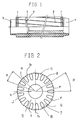
- This sheet has seventeen teeth 7 defining seventeen teeth 8 intended to form the notches of the rotor and surrounding an inner part 9 intended to constitute the cylinder head of the rotor.
- FIG. 3 represents a sheet intended to define the space intended for the intermediate short-circuit ring.
- This sheet corresponding to a sheet according to Figure 2 from which we removed the teeth a, b, c, d, e, f, g, h, i, j, k, that is to say two teeth out of three , except between teeth l and m, taking into account the odd number of teeth.
- the teeth are removed by triggering, after a number of press strokes corresponding to the desired position of the short-circuit ring, and during a number of press strokes corresponding to the thickness of the short-ring desired circuit, an ad hoc punch.
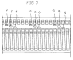
- Figure 4 there are successively three sheets from which teeth are removed.
- FIG. 5 shows, by way of example, a rotor obtained with a rotation of the sheets by an angle corresponding to four teeth, that is to say four ⁇ plus the angle of the propeller. It can be seen that this rotor has the same appearance as the rotor shown in FIG. 4.
- FIGs 6 and 7 show, by way of example, a second embodiment.
- the sheets intended to occupy the space reserved for the short-circuit intermediate ring now have only three teeth f, o and q, using the references used in Figures 2 and 3. These three teeth are approximately evenly distributed over the circumference so that they ensure the centering of the sheet in the casing matrix and during stacking.
- the space reserved for the short-circuit intermediate ring is again obtained by means of three sheets.
- the sheets are driven in rotation by an angle ⁇ , that is to say a pitch increased by the angle of the desired helix.
- the amount of iron in the short-circuit intermediate ring 5 is minimized.
- the interior of the rotor is machined so as to remove the crown 10 connecting the teeth of the sheets located in the intermediate short-circuit ring 5 so as to leave only this intermediate ring.
Landscapes
- Engineering & Computer Science (AREA)
- Power Engineering (AREA)
- Manufacturing & Machinery (AREA)
- Manufacture Of Motors, Generators (AREA)
- Induction Machinery (AREA)
- Heterocyclic Carbon Compounds Containing A Hetero Ring Having Oxygen Or Sulfur (AREA)
Priority Applications (1)
| Application Number | Priority Date | Filing Date | Title |
|---|---|---|---|
| AT88810670T ATE71780T1 (de) | 1987-10-02 | 1988-09-28 | Verfahren zur herstellung eines kaefigankers mit kurzschliessendem zwischenring. |
Applications Claiming Priority (2)
| Application Number | Priority Date | Filing Date | Title |
|---|---|---|---|
| FR8713655 | 1987-10-02 | ||
| FR8713655A FR2621429B1 (fr) | 1987-10-02 | 1987-10-02 | Rotor a cage d'ecureuil comprenant une bague de court-circuit intermediaire et son procede de fabrication |
Publications (2)
| Publication Number | Publication Date |
|---|---|
| EP0314613A1 true EP0314613A1 (de) | 1989-05-03 |
| EP0314613B1 EP0314613B1 (de) | 1992-01-15 |
Family
ID=9355471
Family Applications (1)
| Application Number | Title | Priority Date | Filing Date |
|---|---|---|---|
| EP88810670A Expired - Lifetime EP0314613B1 (de) | 1987-10-02 | 1988-09-28 | Verfahren zur Herstellung eines Käfigankers mit kurzschliessendem Zwischenring |
Country Status (8)
| Country | Link |
|---|---|
| US (1) | US4872256A (de) |
| EP (1) | EP0314613B1 (de) |
| JP (1) | JP2814398B2 (de) |
| AT (1) | ATE71780T1 (de) |
| AU (1) | AU597849B2 (de) |
| DE (1) | DE3867799D1 (de) |
| ES (1) | ES2030208T3 (de) |
| FR (1) | FR2621429B1 (de) |
Cited By (1)
| Publication number | Priority date | Publication date | Assignee | Title |
|---|---|---|---|---|
| EP4020777A1 (de) | 2020-12-24 | 2022-06-29 | Somfy Activites SA | Rotor für einen elektromotor, elektromotor mit einem solchen rotor und herstellungsverfahren eines solchen rotors |
Families Citing this family (2)
| Publication number | Priority date | Publication date | Assignee | Title |
|---|---|---|---|---|
| FR2621429B1 (fr) * | 1987-10-02 | 1990-01-19 | Somfy | Rotor a cage d'ecureuil comprenant une bague de court-circuit intermediaire et son procede de fabrication |
| US7716523B2 (en) | 2007-05-03 | 2010-05-11 | Symantec Corporation | End-to-end transactional protection for requests in a web application |
Citations (5)
| Publication number | Priority date | Publication date | Assignee | Title |
|---|---|---|---|---|
| FR958926A (de) * | 1941-09-02 | 1950-03-21 | ||
| US2971106A (en) * | 1957-12-05 | 1961-02-07 | Westphalen Kurt | Induction motors |
| FR1285836A (fr) * | 1961-04-07 | 1962-02-23 | Brown | Rotor pour moteur asynchrone avec cage d'induit coulée et paquet de tôles divisé |
| DE2649561A1 (de) * | 1975-12-11 | 1977-06-23 | Inst Rade Koncar | Laeufer mit gegossenem kaefig fuer elektromotoren |
| DE2741036A1 (de) * | 1977-09-12 | 1979-05-23 | Siemens Ag | Staffellaeufer fuer eine asynchronmaschine |
Family Cites Families (6)
| Publication number | Priority date | Publication date | Assignee | Title |
|---|---|---|---|---|
| DE2246962C3 (de) * | 1972-09-25 | 1980-02-21 | Siemens Ag, 1000 Berlin U. 8000 Muenchen | Anordnung zur Erhöhung der Axialkraft während des Motoranlaufs bei einem Verschiebeanker-Bremsmotor und Verfahren zur Herstellung einer solchen Anordnung |
| US4445272A (en) * | 1980-06-16 | 1984-05-01 | International Business Machines Corporation | Method and apparatus for stacking rotor blanks on a shaft |
| FR2562348B1 (fr) * | 1984-03-27 | 1988-04-22 | Somfy | Moteur-frein |
| JPS6192143A (ja) * | 1984-10-08 | 1986-05-10 | Matsushita Electric Ind Co Ltd | 電動機の回転子 |
| IT1184585B (it) * | 1985-06-06 | 1987-10-28 | Gianni Tomasini | Attrezzatura per uso odontoiatrico per alesatura di un dente; procedimento relativo |
| FR2621429B1 (fr) * | 1987-10-02 | 1990-01-19 | Somfy | Rotor a cage d'ecureuil comprenant une bague de court-circuit intermediaire et son procede de fabrication |
-
1987
- 1987-10-02 FR FR8713655A patent/FR2621429B1/fr not_active Expired - Lifetime
-
1988
- 1988-09-19 US US07/246,256 patent/US4872256A/en not_active Expired - Fee Related
- 1988-09-27 AU AU22876/88A patent/AU597849B2/en not_active Ceased
- 1988-09-28 JP JP63243744A patent/JP2814398B2/ja not_active Expired - Lifetime
- 1988-09-28 AT AT88810670T patent/ATE71780T1/de active
- 1988-09-28 DE DE8888810670T patent/DE3867799D1/de not_active Expired - Lifetime
- 1988-09-28 EP EP88810670A patent/EP0314613B1/de not_active Expired - Lifetime
- 1988-09-28 ES ES198888810670T patent/ES2030208T3/es not_active Expired - Lifetime
Patent Citations (5)
| Publication number | Priority date | Publication date | Assignee | Title |
|---|---|---|---|---|
| FR958926A (de) * | 1941-09-02 | 1950-03-21 | ||
| US2971106A (en) * | 1957-12-05 | 1961-02-07 | Westphalen Kurt | Induction motors |
| FR1285836A (fr) * | 1961-04-07 | 1962-02-23 | Brown | Rotor pour moteur asynchrone avec cage d'induit coulée et paquet de tôles divisé |
| DE2649561A1 (de) * | 1975-12-11 | 1977-06-23 | Inst Rade Koncar | Laeufer mit gegossenem kaefig fuer elektromotoren |
| DE2741036A1 (de) * | 1977-09-12 | 1979-05-23 | Siemens Ag | Staffellaeufer fuer eine asynchronmaschine |
Non-Patent Citations (1)
| Title |
|---|
| PATENT ABSTRACTS OF JAPAN * |
Cited By (2)
| Publication number | Priority date | Publication date | Assignee | Title |
|---|---|---|---|---|
| EP4020777A1 (de) | 2020-12-24 | 2022-06-29 | Somfy Activites SA | Rotor für einen elektromotor, elektromotor mit einem solchen rotor und herstellungsverfahren eines solchen rotors |
| FR3118545A1 (fr) | 2020-12-24 | 2022-07-01 | Somfy Activites Sa | Rotor pour un moteur électrique, moteur électrique comprenant un tel rotor et procédé de fabrication d’un tel rotor |
Also Published As
| Publication number | Publication date |
|---|---|
| FR2621429A1 (fr) | 1989-04-07 |
| ATE71780T1 (de) | 1992-02-15 |
| FR2621429B1 (fr) | 1990-01-19 |
| DE3867799D1 (de) | 1992-02-27 |
| EP0314613B1 (de) | 1992-01-15 |
| AU597849B2 (en) | 1990-06-07 |
| ES2030208T3 (es) | 1992-10-16 |
| AU2287688A (en) | 1989-04-06 |
| JPH01110038A (ja) | 1989-04-26 |
| US4872256A (en) | 1989-10-10 |
| JP2814398B2 (ja) | 1998-10-22 |
Similar Documents
| Publication | Publication Date | Title |
|---|---|---|
| EP2332232B1 (de) | Stator für eine elektrische rotationsmaschine und herstellungsverfahren dafür | |
| EP3361604A1 (de) | Stator einer elektrisch umlaufenden maschine | |
| EP0765539B1 (de) | Bewickelter, genuteter staender fuer rotierende elektrische maschine, herstellungsverfahren dafuer und elektromotor mit einem derartigen stator | |
| JP7368471B2 (ja) | 電気モータ用のロータ積層板シートおよびステータ積層板シートのような金属部品を製造するための多層打抜き方法および装置 | |
| FR2627643A1 (fr) | Perfectionnements aux rotors induits des ralentisseurs electromagnetiques | |
| EP0314613B1 (de) | Verfahren zur Herstellung eines Käfigankers mit kurzschliessendem Zwischenring | |
| FR2870998A1 (fr) | Stator de machine tournante electrique et procede de fabrication de celui ci | |
| EP3522334B1 (de) | Magnetschaltkreis für element einer elektrisch umlaufenden maschine, entsprechendes verfahren und entsprechende elektrische maschine | |
| JPH06141516A (ja) | 電動モータのコアおよび該コアの製造方法 | |
| EP2860847B1 (de) | Bewickelter Stator mit optimierter Nutenfüllung, und entsprechende elektrische Maschine | |
| EP0500442B1 (de) | Lüfterrad für rotierende elektrische Maschinen, insbesondere für Wechselstromgeneratoren für Kraftfahrzeuge | |
| EP3170246A1 (de) | Verfahren zur herstellung eines gewickelten stators einer elektrischen drehmaschine | |
| EP3534500A1 (de) | Mit einer wicklung versehener rotor oder stator, und herstellungsverfahren | |
| FR2538180A1 (fr) | Moteur electrique | |
| EP3648314A1 (de) | Bürstenloser gleichstrommotor mit einem reduzierten rastmoment, und sein herstellungsverfahren | |
| EP0095962A1 (de) | Verfahren zur Formung von Wickelköpfen am Stator eines elektrischen Motors und gemäss diesem Verfahren hergestellter Stator eines Elektromotors | |
| EP4311086A1 (de) | Vorrichtung zur herstellung eines blechpakets | |
| FR3088152B1 (fr) | Machine electrique tournante et procede de fabrication d'une telle machine | |
| EP0040115B1 (de) | Verfahren zur Herstellung eines Stators für dynamo-elektrische Maschinen, Rohling und nach diesem Verfahren erhaltener Stator | |
| EP3123595B1 (de) | Geschmiedetes polrad für eine kraftfahrzeuglichtmaschine mit interpolaren permanentmagneten | |
| FR3064837A1 (fr) | Rotor pour machine electrique a aimants permanents internes | |
| FR2532789A1 (fr) | Collecteur de machine electique tournante, et son procede de fabrication | |
| FR2846806A1 (fr) | Procede de fabrication de conducteurs electriques en forme d'epingles en u, dispositif pour la mise en oeuvre de ce procede et conducteurs ainsi obtenus | |
| FR2488534A3 (fr) | Procede d'obtention d'une poulie multigorges et poulie ainsi obtenue | |
| EP0157707A2 (de) | Verfahren für die Herstellung einer Spule für einen Synchronmotor mit Dauermagneten zum Antrieb eines Gyroskops |
Legal Events
| Date | Code | Title | Description |
|---|---|---|---|
| PUAI | Public reference made under article 153(3) epc to a published international application that has entered the european phase |
Free format text: ORIGINAL CODE: 0009012 |
|
| AK | Designated contracting states |
Kind code of ref document: A1 Designated state(s): AT BE CH DE ES GB IT LI NL SE |
|
| 17P | Request for examination filed |
Effective date: 19890707 |
|
| 17Q | First examination report despatched |
Effective date: 19910503 |
|
| GRAA | (expected) grant |
Free format text: ORIGINAL CODE: 0009210 |
|
| AK | Designated contracting states |
Kind code of ref document: B1 Designated state(s): AT BE CH DE ES GB IT LI NL SE |
|
| PG25 | Lapsed in a contracting state [announced via postgrant information from national office to epo] |
Ref country code: SE Effective date: 19920115 Ref country code: AT Effective date: 19920115 |
|
| REF | Corresponds to: |
Ref document number: 71780 Country of ref document: AT Date of ref document: 19920215 Kind code of ref document: T |
|
| ITF | It: translation for a ep patent filed | ||
| REF | Corresponds to: |
Ref document number: 3867799 Country of ref document: DE Date of ref document: 19920227 |
|
| GBT | Gb: translation of ep patent filed (gb section 77(6)(a)/1977) | ||
| REG | Reference to a national code |
Ref country code: ES Ref legal event code: FG2A Ref document number: 2030208 Country of ref document: ES Kind code of ref document: T3 |
|
| PLBE | No opposition filed within time limit |
Free format text: ORIGINAL CODE: 0009261 |
|
| STAA | Information on the status of an ep patent application or granted ep patent |
Free format text: STATUS: NO OPPOSITION FILED WITHIN TIME LIMIT |
|
| 26N | No opposition filed | ||
| PGFP | Annual fee paid to national office [announced via postgrant information from national office to epo] |
Ref country code: CH Payment date: 19950727 Year of fee payment: 8 |
|
| PGFP | Annual fee paid to national office [announced via postgrant information from national office to epo] |
Ref country code: GB Payment date: 19950919 Year of fee payment: 8 |
|
| PGFP | Annual fee paid to national office [announced via postgrant information from national office to epo] |
Ref country code: NL Payment date: 19950922 Year of fee payment: 8 |
|
| PGFP | Annual fee paid to national office [announced via postgrant information from national office to epo] |
Ref country code: BE Payment date: 19951110 Year of fee payment: 8 |
|
| PG25 | Lapsed in a contracting state [announced via postgrant information from national office to epo] |
Ref country code: GB Effective date: 19960928 |
|
| PG25 | Lapsed in a contracting state [announced via postgrant information from national office to epo] |
Ref country code: LI Effective date: 19960930 Ref country code: CH Effective date: 19960930 Ref country code: BE Effective date: 19960930 |
|
| BERE | Be: lapsed |
Owner name: SOMFY Effective date: 19960930 |
|
| PG25 | Lapsed in a contracting state [announced via postgrant information from national office to epo] |
Ref country code: NL Effective date: 19970401 |
|
| REG | Reference to a national code |
Ref country code: CH Ref legal event code: PL |
|
| GBPC | Gb: european patent ceased through non-payment of renewal fee |
Effective date: 19960928 |
|
| NLV4 | Nl: lapsed or anulled due to non-payment of the annual fee |
Effective date: 19970401 |
|
| PGFP | Annual fee paid to national office [announced via postgrant information from national office to epo] |
Ref country code: ES Payment date: 19970930 Year of fee payment: 10 |
|
| PGFP | Annual fee paid to national office [announced via postgrant information from national office to epo] |
Ref country code: DE Payment date: 19980828 Year of fee payment: 11 |
|
| PG25 | Lapsed in a contracting state [announced via postgrant information from national office to epo] |
Ref country code: ES Free format text: LAPSE BECAUSE OF THE APPLICANT RENOUNCES Effective date: 19980929 |
|
| PG25 | Lapsed in a contracting state [announced via postgrant information from national office to epo] |
Ref country code: DE Free format text: LAPSE BECAUSE OF NON-PAYMENT OF DUE FEES Effective date: 20000701 |
|
| REG | Reference to a national code |
Ref country code: ES Ref legal event code: FD2A Effective date: 20001009 |
|
| PG25 | Lapsed in a contracting state [announced via postgrant information from national office to epo] |
Ref country code: IT Free format text: LAPSE BECAUSE OF NON-PAYMENT OF DUE FEES;WARNING: LAPSES OF ITALIAN PATENTS WITH EFFECTIVE DATE BEFORE 2007 MAY HAVE OCCURRED AT ANY TIME BEFORE 2007. THE CORRECT EFFECTIVE DATE MAY BE DIFFERENT FROM THE ONE RECORDED. Effective date: 20050928 |