EP0314634A2 - Vorrichtung zum Läppen von inneren Oberflächen - Google Patents
Vorrichtung zum Läppen von inneren Oberflächen Download PDFInfo
- Publication number
- EP0314634A2 EP0314634A2 EP19880830426 EP88830426A EP0314634A2 EP 0314634 A2 EP0314634 A2 EP 0314634A2 EP 19880830426 EP19880830426 EP 19880830426 EP 88830426 A EP88830426 A EP 88830426A EP 0314634 A2 EP0314634 A2 EP 0314634A2
- Authority
- EP
- European Patent Office
- Prior art keywords
- rod
- cone
- equipment
- lapping
- spindle
- Prior art date
- Legal status (The legal status is an assumption and is not a legal conclusion. Google has not performed a legal analysis and makes no representation as to the accuracy of the status listed.)
- Granted
Links
- 239000002131 composite material Substances 0.000 claims abstract description 14
- 230000008878 coupling Effects 0.000 claims abstract description 11
- 238000010168 coupling process Methods 0.000 claims abstract description 11
- 238000005859 coupling reaction Methods 0.000 claims abstract description 11
- 230000007246 mechanism Effects 0.000 claims abstract description 7
- 230000002093 peripheral effect Effects 0.000 claims abstract description 5
- 229910003460 diamond Inorganic materials 0.000 claims description 8
- 239000010432 diamond Substances 0.000 claims description 8
- 230000007423 decrease Effects 0.000 claims description 2
- 230000008901 benefit Effects 0.000 description 4
- 230000009471 action Effects 0.000 description 3
- 238000007667 floating Methods 0.000 description 3
- 238000010276 construction Methods 0.000 description 2
- 230000000694 effects Effects 0.000 description 2
- 239000000463 material Substances 0.000 description 2
- 230000013011 mating Effects 0.000 description 2
- 238000000034 method Methods 0.000 description 2
- 240000005561 Musa balbisiana Species 0.000 description 1
- 235000018290 Musa x paradisiaca Nutrition 0.000 description 1
- 230000007547 defect Effects 0.000 description 1
- 230000001419 dependent effect Effects 0.000 description 1
- 238000007730 finishing process Methods 0.000 description 1
- 238000010438 heat treatment Methods 0.000 description 1
- 238000003754 machining Methods 0.000 description 1
- 230000010355 oscillation Effects 0.000 description 1
- 238000005498 polishing Methods 0.000 description 1
- 230000008569 process Effects 0.000 description 1
- 239000000725 suspension Substances 0.000 description 1
Images

Classifications
-
- B—PERFORMING OPERATIONS; TRANSPORTING
- B24—GRINDING; POLISHING
- B24B—MACHINES, DEVICES, OR PROCESSES FOR GRINDING OR POLISHING; DRESSING OR CONDITIONING OF ABRADING SURFACES; FEEDING OF GRINDING, POLISHING, OR LAPPING AGENTS
- B24B33/00—Honing machines or devices; Accessories therefor
- B24B33/10—Accessories
-
- B—PERFORMING OPERATIONS; TRANSPORTING
- B23—MACHINE TOOLS; METAL-WORKING NOT OTHERWISE PROVIDED FOR
- B23Q—DETAILS, COMPONENTS, OR ACCESSORIES FOR MACHINE TOOLS, e.g. ARRANGEMENTS FOR COPYING OR CONTROLLING; MACHINE TOOLS IN GENERAL CHARACTERISED BY THE CONSTRUCTION OF PARTICULAR DETAILS OR COMPONENTS; COMBINATIONS OR ASSOCIATIONS OF METAL-WORKING MACHINES, NOT DIRECTED TO A PARTICULAR RESULT
- B23Q1/00—Members which are comprised in the general build-up of a form of machine, particularly relatively large fixed members
- B23Q1/25—Movable or adjustable work or tool supports
- B23Q1/26—Movable or adjustable work or tool supports characterised by constructional features relating to the co-operation of relatively movable members; Means for preventing relative movement of such members
- B23Q1/34—Relative movement obtained by use of deformable elements, e.g. piezoelectric, magnetostrictive, elastic or thermally-dilatable elements
- B23Q1/36—Springs
-
- B—PERFORMING OPERATIONS; TRANSPORTING
- B24—GRINDING; POLISHING
- B24B—MACHINES, DEVICES, OR PROCESSES FOR GRINDING OR POLISHING; DRESSING OR CONDITIONING OF ABRADING SURFACES; FEEDING OF GRINDING, POLISHING, OR LAPPING AGENTS
- B24B33/00—Honing machines or devices; Accessories therefor
- B24B33/08—Honing tools
-
- B—PERFORMING OPERATIONS; TRANSPORTING
- B24—GRINDING; POLISHING
- B24B—MACHINES, DEVICES, OR PROCESSES FOR GRINDING OR POLISHING; DRESSING OR CONDITIONING OF ABRADING SURFACES; FEEDING OF GRINDING, POLISHING, OR LAPPING AGENTS
- B24B41/00—Component parts such as frames, beds, carriages, headstocks
- B24B41/06—Work supports, e.g. adjustable steadies
-
- Y—GENERAL TAGGING OF NEW TECHNOLOGICAL DEVELOPMENTS; GENERAL TAGGING OF CROSS-SECTIONAL TECHNOLOGIES SPANNING OVER SEVERAL SECTIONS OF THE IPC; TECHNICAL SUBJECTS COVERED BY FORMER USPC CROSS-REFERENCE ART COLLECTIONS [XRACs] AND DIGESTS
- Y10—TECHNICAL SUBJECTS COVERED BY FORMER USPC
- Y10S—TECHNICAL SUBJECTS COVERED BY FORMER USPC CROSS-REFERENCE ART COLLECTIONS [XRACs] AND DIGESTS
- Y10S451/00—Abrading
- Y10S451/905—Metal lap
Definitions
- the invention relates to improved equipment for lapping internal surfaces.
- lapping machines or lapping equipment, to effect polishing and truing operations that call for a high quality precision finish, for example, such as presented by the bores of parts manufactured to prescribed fit tolerances; a typical case in point is that of the barrels of hydraulic and pneumatic cylinders.
- the operation effected with lapping equipment is a finishing process; work to be lapped may be either heat-treated or untreated, heat treatment being adopted where the work is to be guaranteed a given degree of surface hardness. An initial machining or grinding pass may be made, whereupon the lapping operation will constitute the final step.
- the lap comprises: a support rod, the top end of which is associated with a floating spindle; a cone, ensheathing the rod and allowed a certain freedom of transverse movement relative thereto; and an abrasive diamond shell that is fitted rigidly over the cone.
- the freedom of the cone to shift in relation to the rod is obtained in this instance by leaving a slight clearance between the two parts, and supporting the cone on two moderately loose pins; these are fitted one at either side, at dissimilar distances from the end of the rod, and thus interconnect the two parts. Accordingly, the cone and the rod are prevented from separating, and a marginal float is permitted, the extent of which being dependent upon the clearance allowed.
- the lap and the chucking fixture thus described are suitable for bores of a given diameter, but tend to create problems when lapping notably small bores. More exactly, with a small diameter lapping tool of the composite type in question, the walls of the cone and the diamond shell are necessarily thin, so that if an obstacle should be encountered, or at all events, should the tool's speed of rotation drop for any reason, the rod immediately becomes subject to increased torque. This higher torque is transmitted through the rod to the cone and shell by way of the two pins, with stresses concentrated particularly on the opposite ends of the pins. However, the cone and the abrasive shell will often not be thick enough to sustain the thrust with which they are invested by the ends of the pins, and are forced outwards and distorted as a result.
- the object of the invention is one of overcoming the drawbacks mentioned above, both from the standpoint of the lapping tool and from that of the work chucking fixture.
- Improved equipment according to the invention is of the type utilizing a chuck to hold the work, and a composite lapping tool that consists in a vertical rod ensheathed by a marginally loose fitting cone supporting a diamond shell, and features a lap rod embodied in three rigidly associated sections: a bottom section of polygonal transverse profile engaging to an exact fit in a corresponding axial socket offered by the cone and locked in position axially by means of a diametral pin; a middle section, possessing a degree of flexibility commensurate with the tolerances prescribed for the work, whilst ensuring sufficient torsional rigidity to function as a flexible coupling; and a top section connected to the spindle.
- the improved work chucking fixture according to the invention is suspended from at least three cables which pass through respective peripheral mountings integral with the chuck; thus, chuck and work can shift bodily in any given plane, and are provided with a cushioning system at one and the same time.
- One of the advantages of the invention is that of its adaptability to different sizes of bore to be lapped, and to varying sizes of workpiece, inasmuch as torque is transmitted from the rod to the cone through polygonal mating surfaces; accordingly, the area through which these two parts make contact is generous, and distributed uniformly about the axis of the abrasive shell, however small the overall diameter.
- the mobility of the chuck can be adjusted by tautening or slackening the cables to suit the weight of the work, and offset mechanical resistance, if any, generated by the lapping action.
- the three-stage embodiment of the lap rod is instrumental in obtaining a more accurate seating of the lap internally of the bore to be finished, thanks to the combined elasticity and resilience of the middle section and its ability to function as a flexible coupling.
- Another advantage of the invention is that it is simple in construction, and therefore advantageous from the cost standpoint; in effect, the only parts requiring any significant degree of precision are the polygonal bottom section of the lap rod and the matching socket of the cone.
- Yet another advantage of the invention is that the stresses transmitted through the lap rod to the cone and shell can be reduced practically at will, since mating contact occurs across the entire expanse of the polygonal profile offered by the bottom section of the rod, and accordingly, this same polygonal profile can be lengthened or shortened, so as to reduce or increase mechanical pressure on the cone during the lapping process.
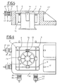
- the improved equipment disclosed of the type used for lapping internal surfaces, consists essentially in a vertically disposed composite lapping tool 12, fastened directly or indirectly in conventional fashion to an overhead spindle 11, and a chucking fixture 1 mounted to the bed of the lapping machine (not illustrated).
- the composite lap 12 illustrated in fig 1 consists in a rod 2, located uppermost and connected by its top end to the spindle 11, a cone 3, located below and carried by the rod 2, and an abrasive diamond shell 4 that ensheaths the cone 3 to an exact fit.
- the cone 3 exhibits an axial hole 13 with an open top end in which the bottom end of the rod 2 is freely inserted, the degree of clearance allowed being compatible with the tolerances prescribed for the lapping operation.
- the diamond shell 4 which constitutes the abrasive part proper of the composite lap 12, is fitted to and removable from the cone 3 by conventional means such as lock nuts 23 and 24, for example, that screw onto corresponding threads offered by the ends of the cone 3 and clamp the shell 4 from either end, as illustrated in fig 1.
- the rod 2 is embodied in three sections, 7, 8 and 9, which are associated rigidly and coaxially one with the next.
- the bottom section or tip exhibits a polygonal, preferably hexagonal transverse profile (discernable in fig 2), and a diametrically disposed hole 25 serving to accommodate a pin.
- the polygonal tip 7 is insertable to an exact fit in a matching polygonal socket 13a afforded by the axial hole 13 of the cone 3, which also presents a diametrically disposed hole 26 positioned to coincide coaxially with the hole 25 of the tip 7.
- the hex tip 7 denotes the aforementioned pin, which inserts to an exact fit in the holes 25 and 26 offered by the hex tip 7 and socket 13a, thereby furnishing the means by which the rod and cone parts 2 and 3 of the composite tool 12 are connected, and constituting the sole means by which the cone 3 is supported.
- the length of the hex tip 7 will depend first and foremost on the external diameter of the abrasive shell 4: the smaller the diameter of the shell 4, the greater the length of the hex tip 7.
- the hex tip 7 coincides with the centre of balance of the composite tool, so as to avoid overloading the bottom end and ensure better balance overall.
- the middle section of the rod 2 denoted 8, referred to hereinafter as a coupling (the reasons for which will shortly become clear), is embodied in material possessing a given degree of flexibility that will be commensurate with the tolerances prescribed for the lapped work, though sufficient at all events to ensure good torsional rigidity.
- the coupling 8 consists in a longitudinal element embodied as a tightly coiled helicoid, i.e. with no gaps between the turns of the helix, generated in the opposite direction to that in which the lap 12 turns with the spindle 11; the coupling 8 is accommodated freely by the axial hole 13 of the cone 3, the degree of clearance being compatible with the prescribed lapping tolerances.
- the top section, or shank 9 of the rod 2 exhibits a stretch of diameter substantially identical to that of the coupling 8, an intermediate boss 27 of wider transverse dimensions, and a screw thread 28 at the very top end.
- the boss 27 affords two flat parallel faces that can be engaged by a key or wrench to the end of tightening the screw thread 28 in the female thread of a holder, integral with or fitted to the spindle 11.
- the method of assembling an improved lapping tool 12 according to the invention is substantially the same as for a conventional composite tool, and therefore will not be described.
- the abrasive shell 4 is capable of movement in relation to the rod 2 by virtue both of the clearance existing between rod and cone 3, and of the elastic properties of the coupling 8, which are such as to make the rod advantageously flexible while ensuring that it retains a sufficient degree of torsional rigidity.
- the coupling 8 provides a further marked advantage, namely, the capacity to function as a safety device in the event of some unforeseen obstacle slowing down or jamming the shell 4. More exactly, the coupling 8 can be proportioned in the manner of a shear pin, i.e. capable of transmitting torque only up to a given maximum value, in excess of which it will break, preventing damage either to the work or to other components of the equipment.
- the chucking fixture 1 which, for example, might be a conventional type self-aligning chucking mechanism, this is suspended from at least three longitudinal elements, embodied as cables 5 and 6, anchored to fixed supports provided by the side walls of a vertically disposed hollow frame 16 (see fig 4) that is made fast to the machine bed in conventional manner.
- the cables 5 and 6 are arranged in two pairs, set at different heights in order to avoid mutual contact; it will be seen, in fact, that the two cables of each pair are parallel and disposed at right angles to those of the remaining pair.
- the cables 5 and 6 associate with the chuck 1 by way of four peripheral hollow mountings 14, fitted in pairs and occupying positions that are diametrically opposed in relation to the vertical axis of the chuck 1.
- the diameter of the passage 15 through each mounting 14 decreases from the ends toward the middle, creating what is a substantially biconical, hourglass type profile the waisted portion of which is rounded so as to avoid any excessive build-up of tension at that point.
- the minimum diameter of the passage 15 substantially matches the diameter of the respective cable 5 or 6, in such a way as to prevent any unwanted sideways movement of the chuck 1 in relation to the cables 5 and 6.
- each cable 5 and 6 pass through the side walls of the frame 16, and are prevented from working free by relative fixed and removable locking elements 17 located externally of the frame.
- each cable 5 and 6 is secured by one fixed element 17, and one removable element, or clamp.
- each cable 5 and 6 denotes a device encircling each cable 5 and 6 at one end, located between the relative clamp 17 and the frame 16, which serves to adjust the tension of the cable with which it is associated.
- Each such device 18 consists in an externally threaded hollow member 19 associated rigidly with the cable 5 or 6, an adjuster nut 20 screwed onto the threaded member 19, and a set of belleville disc springs 21 through which the threaded member 19 is inserted.
- a distance collar 22 may also be added, as illustrated in figs 4 and 5.
- the relative cable 5 or 6 can be tensioned or slackened to suit the size of the work, and more important, to suit its weight.
- the cables 5 and 6 will need to be well tightened for large and bulky items, so as to avoid too loose a suspension, whereas a slacker setting is needed for lighter work in order to permit a reasonable freedom of movement as the lap 12 enters the bore.
- the cables 5 and 6 are always sure of a certain degree of elasticity thanks to the action of the springs 21, which will rarely be compressed to the limit.
- the middle section 8 of the lap rod 2 might be fashioned solidly in a material with the appropriate flexible and torsional properties, or a small universal joint could even be incorporated.
Landscapes
- Engineering & Computer Science (AREA)
- Mechanical Engineering (AREA)
- Finish Polishing, Edge Sharpening, And Grinding By Specific Grinding Devices (AREA)
- Polishing Bodies And Polishing Tools (AREA)
Priority Applications (1)
| Application Number | Priority Date | Filing Date | Title |
|---|---|---|---|
| EP92118100A EP0526914B1 (de) | 1987-10-30 | 1988-10-20 | Vorrichtung zum Läppen von inneren Oberflächen |
Applications Claiming Priority (2)
| Application Number | Priority Date | Filing Date | Title |
|---|---|---|---|
| IT03676/87A IT1221550B (it) | 1987-10-30 | 1987-10-30 | Apparecchiatura perfezionata per la lappatura di interni |
| IT367687 | 1987-10-30 |
Related Child Applications (1)
| Application Number | Title | Priority Date | Filing Date |
|---|---|---|---|
| EP92118100.4 Division-Into | 1992-10-22 |
Publications (3)
| Publication Number | Publication Date |
|---|---|
| EP0314634A2 true EP0314634A2 (de) | 1989-05-03 |
| EP0314634A3 EP0314634A3 (en) | 1990-09-19 |
| EP0314634B1 EP0314634B1 (de) | 1994-05-18 |
Family
ID=11111331
Family Applications (2)
| Application Number | Title | Priority Date | Filing Date |
|---|---|---|---|
| EP88830426A Expired - Lifetime EP0314634B1 (de) | 1987-10-30 | 1988-10-20 | Vorrichtung zum Läppen von inneren Oberflächen |
| EP92118100A Expired - Lifetime EP0526914B1 (de) | 1987-10-30 | 1988-10-20 | Vorrichtung zum Läppen von inneren Oberflächen |
Family Applications After (1)
| Application Number | Title | Priority Date | Filing Date |
|---|---|---|---|
| EP92118100A Expired - Lifetime EP0526914B1 (de) | 1987-10-30 | 1988-10-20 | Vorrichtung zum Läppen von inneren Oberflächen |
Country Status (5)
| Country | Link |
|---|---|
| US (1) | US4928434A (de) |
| EP (2) | EP0314634B1 (de) |
| DE (2) | DE3854868T2 (de) |
| ES (2) | ES2053813T3 (de) |
| IT (1) | IT1221550B (de) |
Cited By (1)
| Publication number | Priority date | Publication date | Assignee | Title |
|---|---|---|---|---|
| DE3942256A1 (de) * | 1989-12-21 | 1991-07-04 | Nagel Masch Werkzeug | Bearbeitungsvorrichtung, insbesondere honeinrichtung |
Families Citing this family (7)
| Publication number | Priority date | Publication date | Assignee | Title |
|---|---|---|---|---|
| USD726133S1 (en) | 2012-03-20 | 2015-04-07 | Veeco Instruments Inc. | Keyed spindle |
| US9816184B2 (en) | 2012-03-20 | 2017-11-14 | Veeco Instruments Inc. | Keyed wafer carrier |
| USD712852S1 (en) * | 2012-03-20 | 2014-09-09 | Veeco Instruments Inc. | Spindle key |
| CN105031877A (zh) * | 2015-07-01 | 2015-11-11 | 张明智 | 一种手腕臂健力器 |
| CN105500028B (zh) * | 2016-01-18 | 2018-09-25 | 惠州智科实业有限公司 | 一种cnc工作台 |
| CN112917256B (zh) * | 2021-01-25 | 2022-02-08 | 重庆北鑫机电有限公司 | 一种防磨边的机电用金属工件打磨装置 |
| CN112975734B (zh) * | 2021-04-26 | 2021-08-06 | 常州凯瑞莱精密工具有限公司 | 珩磨进给机构及具有该机构的立式珩磨机 |
Family Cites Families (14)
| Publication number | Priority date | Publication date | Assignee | Title |
|---|---|---|---|---|
| GB434500A (en) * | 1934-03-08 | 1935-09-03 | Robert Owen Harper | Honing apparatus |
| US2170329A (en) * | 1937-11-10 | 1939-08-22 | William E Hoke | Apparatus for lapping or abrading |
| GB705452A (en) * | 1952-01-26 | 1954-03-10 | Vivian Charles Eric Marten Gwi | A portable boring, reaming and honing machine for automobile cylinders |
| US3352067A (en) * | 1965-03-30 | 1967-11-14 | Barnes Drill Co | Automatic sizing device for a honing machine |
| DE1677168A1 (de) * | 1967-03-09 | 1971-04-29 | Franke Gmbh Edelstahlerzeugnis | Schleif- und Poliervorrichtung |
| JPS553679B2 (de) * | 1973-08-27 | 1980-01-26 | ||
| CH594311A5 (de) * | 1975-08-29 | 1978-01-13 | Bbc Brown Boveri & Cie | |
| US4051637A (en) * | 1977-03-16 | 1977-10-04 | Norikazu Takeishi | Cylinder internal grinder |
| FR2407794A1 (fr) * | 1977-11-03 | 1979-06-01 | Citroen Sa | Rodoir expansible pour rodage de haute precision |
| JPS5834749A (ja) * | 1981-08-13 | 1983-03-01 | Minatogumi:Goushi | 管内面研削機 |
| DE3219629C2 (de) * | 1982-05-25 | 1986-02-13 | Peter 7442 Neuffen Nagel | Verbindungselement zur Übertragung einer Drehbewegung |
| SU1060423A1 (ru) * | 1982-08-26 | 1983-12-15 | Государственное Проектное Конструкторско-Технологическое Бюро Машиностроения Научно-Производственного Объединения "Технолог" | Устройство дл абразивной обработки |
| US4694477A (en) * | 1983-12-21 | 1987-09-15 | Hewlett-Packard Company | Flexure stage alignment apparatus |
| US4615152A (en) * | 1985-11-08 | 1986-10-07 | Ammco Tools, Inc. | Cylinder hone |
-
1987
- 1987-10-30 IT IT03676/87A patent/IT1221550B/it active
-
1988
- 1988-10-07 US US07/254,699 patent/US4928434A/en not_active Expired - Fee Related
- 1988-10-20 EP EP88830426A patent/EP0314634B1/de not_active Expired - Lifetime
- 1988-10-20 EP EP92118100A patent/EP0526914B1/de not_active Expired - Lifetime
- 1988-10-20 DE DE3854868T patent/DE3854868T2/de not_active Expired - Fee Related
- 1988-10-20 DE DE3889620T patent/DE3889620T2/de not_active Expired - Fee Related
- 1988-10-20 ES ES88830426T patent/ES2053813T3/es not_active Expired - Lifetime
- 1988-10-20 ES ES92118100T patent/ES2083053T3/es not_active Expired - Lifetime
Cited By (1)
| Publication number | Priority date | Publication date | Assignee | Title |
|---|---|---|---|---|
| DE3942256A1 (de) * | 1989-12-21 | 1991-07-04 | Nagel Masch Werkzeug | Bearbeitungsvorrichtung, insbesondere honeinrichtung |
Also Published As
| Publication number | Publication date |
|---|---|
| DE3889620T2 (de) | 1994-11-17 |
| DE3854868T2 (de) | 1996-06-05 |
| US4928434A (en) | 1990-05-29 |
| EP0526914A2 (de) | 1993-02-10 |
| EP0526914B1 (de) | 1996-01-03 |
| EP0526914A3 (en) | 1993-06-09 |
| ES2083053T3 (es) | 1996-04-01 |
| DE3854868D1 (de) | 1996-02-15 |
| EP0314634B1 (de) | 1994-05-18 |
| ES2053813T3 (es) | 1994-08-01 |
| DE3889620D1 (de) | 1994-06-23 |
| IT8703676A0 (it) | 1987-10-30 |
| EP0314634A3 (en) | 1990-09-19 |
| IT1221550B (it) | 1990-07-12 |
Similar Documents
| Publication | Publication Date | Title |
|---|---|---|
| EP0807491B1 (de) | Halterung für optische Linsen und Verfahren zum Polieren von Linsen | |
| EP1248692B1 (de) | Abstimmbare bohrstange zum unterdrücken von schwingungen und dessen methode | |
| KR960004233B1 (ko) | 공작물 또는 공구캐리어와 이들을 위한 조작기 사이의 커플링시스템 | |
| US4192521A (en) | 4-Jaw work holding chucks | |
| US4928434A (en) | Lapping internal surfaces | |
| US5667432A (en) | Grinding machine | |
| JPH0435297B2 (de) | ||
| CA2124431A1 (en) | Spindle extension with self-contained pull-stud draw bar assembly | |
| KR20010093805A (ko) | 중심에 형상오차를 갖는 공작물의 연마방법과 장치 | |
| US8511942B2 (en) | Machine tool with adjustable cutting insert | |
| US5492441A (en) | Clamping device for connecting machine spindles with tool holders | |
| US9975181B2 (en) | Workpiece clamping device with face driver | |
| CN116600922A (zh) | 刀具头和用于运行刀具头的方法以及具有这种刀具头的机床 | |
| DE4328987C1 (de) | Verwendung einer Schleifvorrichtung zum Feinschleifen von Kraftfahrzeugbremsen | |
| WO2011059945A1 (en) | Compensating workholding equipment | |
| CN103358158B (zh) | 5面加工附件 | |
| CN1413786A (zh) | 钻床 | |
| US5865667A (en) | Grinding machine | |
| CN208132590U (zh) | 用于制动盘的研磨装置 | |
| US5251510A (en) | Ring gear fixture and machining process therefor | |
| US6869083B2 (en) | Eccentric work piece holder and method of making same | |
| US6824142B2 (en) | Method of alignably supporting a work piece for rotary movements | |
| US5201617A (en) | Apparatus for supporting a machine tool on a robot arm | |
| US20240042536A1 (en) | Hub flange for a tool body | |
| US9586269B2 (en) | Collet adapter |
Legal Events
| Date | Code | Title | Description |
|---|---|---|---|
| PUAI | Public reference made under article 153(3) epc to a published international application that has entered the european phase |
Free format text: ORIGINAL CODE: 0009012 |
|
| AK | Designated contracting states |
Kind code of ref document: A2 Designated state(s): CH DE ES FR GB LI |
|
| PUAL | Search report despatched |
Free format text: ORIGINAL CODE: 0009013 |
|
| AK | Designated contracting states |
Kind code of ref document: A3 Designated state(s): CH DE ES FR GB LI |
|
| 17P | Request for examination filed |
Effective date: 19901116 |
|
| 17Q | First examination report despatched |
Effective date: 19920430 |
|
| RAP3 | Party data changed (applicant data changed or rights of an application transferred) |
Owner name: TRIMATE S.A.S. DI CASSANELLI GIANFRANCO & C. |
|
| RAP3 | Party data changed (applicant data changed or rights of an application transferred) |
Owner name: TRIMATE S.A.S. DI LONGO SILVANA E C. |
|
| GRAA | (expected) grant |
Free format text: ORIGINAL CODE: 0009210 |
|
| AK | Designated contracting states |
Kind code of ref document: B1 Designated state(s): CH DE ES FR GB LI |
|
| XX | Miscellaneous (additional remarks) |
Free format text: TEILANMELDUNG 92118100.4 EINGEREICHT AM 20/10/88. |
|
| REF | Corresponds to: |
Ref document number: 3889620 Country of ref document: DE Date of ref document: 19940623 |
|
| ET | Fr: translation filed | ||
| REG | Reference to a national code |
Ref country code: ES Ref legal event code: FG2A Ref document number: 2053813 Country of ref document: ES Kind code of ref document: T3 |
|
| PLBE | No opposition filed within time limit |
Free format text: ORIGINAL CODE: 0009261 |
|
| STAA | Information on the status of an ep patent application or granted ep patent |
Free format text: STATUS: NO OPPOSITION FILED WITHIN TIME LIMIT |
|
| 26N | No opposition filed | ||
| PGFP | Annual fee paid to national office [announced via postgrant information from national office to epo] |
Ref country code: GB Payment date: 19971017 Year of fee payment: 10 |
|
| PGFP | Annual fee paid to national office [announced via postgrant information from national office to epo] |
Ref country code: FR Payment date: 19971023 Year of fee payment: 10 |
|
| PGFP | Annual fee paid to national office [announced via postgrant information from national office to epo] |
Ref country code: DE Payment date: 19971024 Year of fee payment: 10 |
|
| PGFP | Annual fee paid to national office [announced via postgrant information from national office to epo] |
Ref country code: CH Payment date: 19971106 Year of fee payment: 10 |
|
| PGFP | Annual fee paid to national office [announced via postgrant information from national office to epo] |
Ref country code: ES Payment date: 19971128 Year of fee payment: 10 |
|
| PG25 | Lapsed in a contracting state [announced via postgrant information from national office to epo] |
Ref country code: GB Free format text: LAPSE BECAUSE OF NON-PAYMENT OF DUE FEES Effective date: 19981020 |
|
| PG25 | Lapsed in a contracting state [announced via postgrant information from national office to epo] |
Ref country code: ES Free format text: LAPSE BECAUSE OF NON-PAYMENT OF DUE FEES Effective date: 19981021 |
|
| PG25 | Lapsed in a contracting state [announced via postgrant information from national office to epo] |
Ref country code: LI Free format text: LAPSE BECAUSE OF NON-PAYMENT OF DUE FEES Effective date: 19981031 Ref country code: CH Free format text: LAPSE BECAUSE OF NON-PAYMENT OF DUE FEES Effective date: 19981031 |
|
| GBPC | Gb: european patent ceased through non-payment of renewal fee |
Effective date: 19981020 |
|
| REG | Reference to a national code |
Ref country code: CH Ref legal event code: PL |
|
| PG25 | Lapsed in a contracting state [announced via postgrant information from national office to epo] |
Ref country code: FR Free format text: LAPSE BECAUSE OF NON-PAYMENT OF DUE FEES Effective date: 19990630 |
|
| REG | Reference to a national code |
Ref country code: FR Ref legal event code: ST |
|
| PG25 | Lapsed in a contracting state [announced via postgrant information from national office to epo] |
Ref country code: DE Free format text: LAPSE BECAUSE OF NON-PAYMENT OF DUE FEES Effective date: 19990803 |
|
| REG | Reference to a national code |
Ref country code: ES Ref legal event code: FD2A Effective date: 19991113 |