EP0314773B1 - Machine motrice ou de travail, notamment machine a combustion interne - Google Patents
Machine motrice ou de travail, notamment machine a combustion interne Download PDFInfo
- Publication number
- EP0314773B1 EP0314773B1 EP88905184A EP88905184A EP0314773B1 EP 0314773 B1 EP0314773 B1 EP 0314773B1 EP 88905184 A EP88905184 A EP 88905184A EP 88905184 A EP88905184 A EP 88905184A EP 0314773 B1 EP0314773 B1 EP 0314773B1
- Authority
- EP
- European Patent Office
- Prior art keywords
- engine
- cylindrical portion
- rod portion
- piston
- connecting rod
- Prior art date
- Legal status (The legal status is an assumption and is not a legal conclusion. Google has not performed a legal analysis and makes no representation as to the accuracy of the status listed.)
- Expired - Lifetime
Links
- 238000002485 combustion reaction Methods 0.000 title claims description 16
- 230000004323 axial length Effects 0.000 claims description 2
- 238000004519 manufacturing process Methods 0.000 claims 5
- 230000000717 retained effect Effects 0.000 claims 1
- 239000000446 fuel Substances 0.000 description 6
- MWUXSHHQAYIFBG-UHFFFAOYSA-N Nitric oxide Chemical compound O=[N] MWUXSHHQAYIFBG-UHFFFAOYSA-N 0.000 description 3
- 238000001816 cooling Methods 0.000 description 2
- 239000007789 gas Substances 0.000 description 2
- 239000003570 air Substances 0.000 description 1
- 238000013459 approach Methods 0.000 description 1
- 238000005452 bending Methods 0.000 description 1
- 239000000567 combustion gas Substances 0.000 description 1
- 238000010276 construction Methods 0.000 description 1
- 230000007423 decrease Effects 0.000 description 1
- 239000002283 diesel fuel Substances 0.000 description 1
- 238000006073 displacement reaction Methods 0.000 description 1
- 239000003344 environmental pollutant Substances 0.000 description 1
- 230000002349 favourable effect Effects 0.000 description 1
- 238000005259 measurement Methods 0.000 description 1
- 239000000203 mixture Substances 0.000 description 1
- 239000010705 motor oil Substances 0.000 description 1
- 239000003921 oil Substances 0.000 description 1
- 235000019198 oils Nutrition 0.000 description 1
- 239000002245 particle Substances 0.000 description 1
- 231100000719 pollutant Toxicity 0.000 description 1
- 239000004071 soot Substances 0.000 description 1
- 235000015112 vegetable and seed oil Nutrition 0.000 description 1
- 239000008158 vegetable oil Substances 0.000 description 1
- XLYOFNOQVPJJNP-UHFFFAOYSA-N water Substances O XLYOFNOQVPJJNP-UHFFFAOYSA-N 0.000 description 1
Images


Classifications
-
- F—MECHANICAL ENGINEERING; LIGHTING; HEATING; WEAPONS; BLASTING
- F02—COMBUSTION ENGINES; HOT-GAS OR COMBUSTION-PRODUCT ENGINE PLANTS
- F02B—INTERNAL-COMBUSTION PISTON ENGINES; COMBUSTION ENGINES IN GENERAL
- F02B75/00—Other engines
- F02B75/04—Engines with variable distances between pistons at top dead-centre positions and cylinder heads
- F02B75/048—Engines with variable distances between pistons at top dead-centre positions and cylinder heads by means of a variable crank stroke length
Definitions
- the invention relates to an engine or working machine, in particular an internal combustion engine with an upper connecting rod section and a lower connecting rod section between the piston and the crankshaft, which are connected to one another by a common joint and in which the two connecting rod sections are supported by an articulated pivot lever on an axle fixed to the motor housing.
- the upper connecting rod section has a strip-shaped web symmetrically in the longitudinal center plane with a cylinder section arranged at the end facing away from the piston, the partial sections of which project beyond the web on both sides and support ring parts of the lower connecting rod section and in that in the upper cylinder section the web plane and recesses are provided in the lower connecting rod section between the ring parts, which are penetrated transversely by a bolt which is eccentrically mounted in the cylinder section at a distance from the cylinder section axis and on which the pivot lever engages with one end.
- the web allows bending stresses to be absorbed and compensated for within limits. Furthermore, a narrow construction of the connecting rod is achieved, so that the counterweights of the crankshaft are kept low and can be designed to save space.
- the lower connecting rod section is formed by halves connected to one another over a partial length by clamping members, for example screws, which each have one of the ring parts on the piston-side ends, the common width of both connecting rod section halves is equal to or less than the axial length of the cylinder section.
- the division of the lower connecting rod section provides the prerequisites for simple assembly of the connecting rod sections and the swivel lever.
- the two ring parts of the lower connecting rod section are supported on the partial sections of the upper connecting rod section instead of known slide bearings by needle bearings.
- the bolt is press-fit by the pivot lever and is held in the cylinder section without displacement by means of the pivot lever.
- 1 is a cylinder, e.g. referred to an internal combustion engine that slidably receives a piston 2.
- the cylinder 1 is closed at the upper end by a plate-shaped cylinder head 3.
- the devices for the supply of fuel and air or fuel mixture and the removal of combustion gases are not shown for reasons of clarity.
- the piston 2 receives, as in particular FIGS. 2 to 6 show a piston pin 32 on which the upper connecting rod section 30 is mounted with its upper bearing 31. Furthermore, the connecting rod section 30 has a cylinder section 33 at the end facing away from the piston 2.
- the bearing 31 and the cylinder portion 33 are connected to each other by a web 34 'extending symmetrically to the longitudinal central axis of the upper connecting rod portion 30'.
- ring parts 36 and 36' of a connecting rod 35 connected to its bearing 34 with the crankshaft 11 are supported.
- the bearing 31, the sections 33 'and 33 ⁇ and the bearing 34 take needle bearings 43.
- a pivot lever 39 extends, which comprises a pin 40 rotatably guided in the sections 33 'and 33 ⁇ with a press fit and with its other end 39th 'Is supported on a support fixed to the motor housing, for example a pin 41 arranged eccentrically on a rotatably adjustable disk 44.
- the bolt 40 with its central axis, as shown in the figures, is offset from the central axis of the cylinder section 33 by an extension 27.
- the design of the connecting rod sections 30 and 35 provides a particularly narrow connecting rod with reduced weight, whereby a favorable mass balance and an advantageous guidance of the crankshaft 11 to the connecting rod can take place.
- the web 34 'of the upper connecting rod section 30 provides free spaces 45 on both sides, through which crankshaft parts, for example mass balancing weights, can be passed.
- the pivot lever 39 acts on the connecting rod sections 30 and 35 in the region of the longitudinal center plane, as a result of which tilting moments on the pivot lever 39 and connecting rod sections 30, 35 are avoided.
- a rotating shaft can also be used as a support member for the pivot lever 39.
- the lower connecting rod section 35 is formed in the exemplary embodiment by halves 35 ', 35 ⁇ , which are formed by clamping members, e.g. Screws 44 are held together. To avoid protruding ends, depressions 46 are provided for receiving the screw heads 47 and nuts 48 of the clamping members.
- the piston 2 is at top dead center.
- the piston pin 32 moves along the cylinder axis 22 and the ring parts 36, 36 'on a movement path in the form of a circular arc 17.
- the bolt 40 moves on a further circular path 21.
- the crankshaft 11 rotates and with it the crankshaft-side bearing 34 in the direction of arrow 19.
- the changes in position of the connecting rod sections 30, 35 and the pivot lever 39 at the bottom dead center of the piston 2 correspond to the dashed lines.
- the corresponding position of the bearing 34 on the crankshaft side is designated by the letters UT.
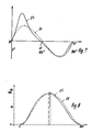
- FIG. 7 shows with the solid line 23 a torque curve in an internal combustion engine of the design according to the invention.
- the 360 ° of a crankshaft revolution is plotted on the abscissa and the torque value determined for constant piston pressure force is plotted on the ordinate.
- the dashed line 24 shows the torque curve in a conventional comparison motor. It can be seen that the maximum torque can be achieved with line 23 at approximately 45 ° crankshaft rotation and with the dashed line at approximately 65 ° crankshaft rotation. If one goes with these values in FIG.
Landscapes
- Engineering & Computer Science (AREA)
- Chemical & Material Sciences (AREA)
- Combustion & Propulsion (AREA)
- Mechanical Engineering (AREA)
- General Engineering & Computer Science (AREA)
- Transmission Devices (AREA)
- Shafts, Cranks, Connecting Bars, And Related Bearings (AREA)
- Harvester Elements (AREA)
Claims (5)
Priority Applications (1)
| Application Number | Priority Date | Filing Date | Title |
|---|---|---|---|
| AT88905184T ATE66721T1 (de) | 1987-05-08 | 1988-05-03 | Kraft- oder arbeitsmaschine, insbesondere verbrennungskraftmaschine. |
Applications Claiming Priority (4)
| Application Number | Priority Date | Filing Date | Title |
|---|---|---|---|
| DE3715391 | 1987-05-08 | ||
| DE19873715391 DE3715391A1 (de) | 1987-05-08 | 1987-05-08 | Brennkraftmaschine oder sonstiger antrieb |
| DE8711187U | 1987-08-17 | ||
| DE8711187 | 1987-08-17 |
Publications (2)
| Publication Number | Publication Date |
|---|---|
| EP0314773A1 EP0314773A1 (fr) | 1989-05-10 |
| EP0314773B1 true EP0314773B1 (fr) | 1991-08-28 |
Family
ID=25855359
Family Applications (1)
| Application Number | Title | Priority Date | Filing Date |
|---|---|---|---|
| EP88905184A Expired - Lifetime EP0314773B1 (fr) | 1987-05-08 | 1988-05-03 | Machine motrice ou de travail, notamment machine a combustion interne |
Country Status (3)
| Country | Link |
|---|---|
| EP (1) | EP0314773B1 (fr) |
| AT (1) | ATE66721T1 (fr) |
| DE (1) | DE3864491D1 (fr) |
Citations (1)
| Publication number | Priority date | Publication date | Assignee | Title |
|---|---|---|---|---|
| EP0292603A1 (fr) * | 1987-05-08 | 1988-11-30 | Gerhard Mederer | Machines à conversion d'énergie, en particulier un moteur à combustion interne |
-
1988
- 1988-05-03 EP EP88905184A patent/EP0314773B1/fr not_active Expired - Lifetime
- 1988-05-03 AT AT88905184T patent/ATE66721T1/de not_active IP Right Cessation
- 1988-05-03 DE DE8888905184T patent/DE3864491D1/de not_active Expired - Lifetime
Patent Citations (1)
| Publication number | Priority date | Publication date | Assignee | Title |
|---|---|---|---|---|
| EP0292603A1 (fr) * | 1987-05-08 | 1988-11-30 | Gerhard Mederer | Machines à conversion d'énergie, en particulier un moteur à combustion interne |
Also Published As
| Publication number | Publication date |
|---|---|
| EP0314773A1 (fr) | 1989-05-10 |
| DE3864491D1 (de) | 1991-10-02 |
| ATE66721T1 (de) | 1991-09-15 |
Similar Documents
| Publication | Publication Date | Title |
|---|---|---|
| EP0292603B1 (fr) | Machines à conversion d'énergie, en particulier un moteur à combustion interne | |
| DE3030615C2 (de) | Brennkraftmaschine | |
| DE7005077U (de) | Ventilsteuerungseinrichtung fuer brennkraftmaschinen. | |
| DE2539047C2 (de) | Hubkolben-Brennkraftmaschine | |
| DE19814870A1 (de) | Hubkolbenbrennkraftmaschine | |
| DE10026634C2 (de) | Vorrichtung zum Verändern der Verdichtung eines Zylinders einer Hubkolbenbrennkraftmaschine | |
| DE2042632A1 (de) | Kolbenmaschine | |
| DE2746203A1 (de) | Verbrennungsmotor | |
| EP0314773B1 (fr) | Machine motrice ou de travail, notamment machine a combustion interne | |
| DE3114459A1 (de) | Kurbeltrieb fuer eine hubkolbenmaschine | |
| DE69100805T2 (de) | System zum erreichen eines viertaktzyklus mit einer umdrehung der kurbelwelle in einer brennkraftmaschine. | |
| DE102011017212A1 (de) | Kurbeltrieb für eine wenigstens ein variabel einstellbares Verdichtungsverhältnis aufweisende Hubkolbenmaschine | |
| DE3129630A1 (de) | Kolbentriebwerk fuer hubkolbenverbrennungskraftmaschine | |
| WO2011107130A1 (fr) | Procédé pour faire fonctionner une machine à piston alternatif | |
| EP0451466B1 (fr) | Moteur à pistons à combustion interne | |
| WO2018033276A1 (fr) | Bielle pour un moteur à combustion interne à compression variable | |
| DE10019959A1 (de) | Brennkraftmaschine | |
| EP0081205B1 (fr) | Moteur à combustion interne à plateau oscillant | |
| DE4239074C2 (de) | Rotationsschwingkolbenmotor | |
| DE19533696A1 (de) | Hubkolben-Brennkraftmaschine | |
| DE2345225C2 (fr) | ||
| DE2422394C2 (fr) | ||
| DE475448C (de) | Getriebe fuer Verbrennungskraftmaschinen mit gegenlaeufigen Kolben | |
| AT524321B1 (de) | Verbrennungskraftmaschine | |
| EP0122299A1 (fr) | Moteur à pistons opposés |
Legal Events
| Date | Code | Title | Description |
|---|---|---|---|
| PUAI | Public reference made under article 153(3) epc to a published international application that has entered the european phase |
Free format text: ORIGINAL CODE: 0009012 |
|
| AK | Designated contracting states |
Kind code of ref document: A1 Designated state(s): AT BE CH DE FR GB IT LI NL SE |
|
| 17P | Request for examination filed |
Effective date: 19890512 |
|
| 17Q | First examination report despatched |
Effective date: 19890821 |
|
| GRAA | (expected) grant |
Free format text: ORIGINAL CODE: 0009210 |
|
| AK | Designated contracting states |
Kind code of ref document: B1 Designated state(s): AT BE CH DE FR GB IT LI NL SE |
|
| PG25 | Lapsed in a contracting state [announced via postgrant information from national office to epo] |
Ref country code: BE Effective date: 19910828 |
|
| REF | Corresponds to: |
Ref document number: 66721 Country of ref document: AT Date of ref document: 19910915 Kind code of ref document: T |
|
| REF | Corresponds to: |
Ref document number: 3864491 Country of ref document: DE Date of ref document: 19911002 |
|
| ITF | It: translation for a ep patent filed | ||
| ET | Fr: translation filed | ||
| GBT | Gb: translation of ep patent filed (gb section 77(6)(a)/1977) | ||
| PLBE | No opposition filed within time limit |
Free format text: ORIGINAL CODE: 0009261 |
|
| STAA | Information on the status of an ep patent application or granted ep patent |
Free format text: STATUS: NO OPPOSITION FILED WITHIN TIME LIMIT |
|
| 26N | No opposition filed | ||
| REG | Reference to a national code |
Ref country code: CH Ref legal event code: PL |
|
| REG | Reference to a national code |
Ref country code: CH Ref legal event code: AEN |
|
| PGFP | Annual fee paid to national office [announced via postgrant information from national office to epo] |
Ref country code: CH Payment date: 19940428 Year of fee payment: 7 |
|
| PGFP | Annual fee paid to national office [announced via postgrant information from national office to epo] |
Ref country code: GB Payment date: 19940510 Year of fee payment: 7 |
|
| PGFP | Annual fee paid to national office [announced via postgrant information from national office to epo] |
Ref country code: SE Payment date: 19940513 Year of fee payment: 7 |
|
| EAL | Se: european patent in force in sweden |
Ref document number: 88905184.3 |
|
| PG25 | Lapsed in a contracting state [announced via postgrant information from national office to epo] |
Ref country code: GB Effective date: 19950503 |
|
| PG25 | Lapsed in a contracting state [announced via postgrant information from national office to epo] |
Ref country code: SE Effective date: 19950504 |
|
| PG25 | Lapsed in a contracting state [announced via postgrant information from national office to epo] |
Ref country code: LI Effective date: 19950531 Ref country code: CH Effective date: 19950531 |
|
| GBPC | Gb: european patent ceased through non-payment of renewal fee |
Effective date: 19950503 |
|
| REG | Reference to a national code |
Ref country code: CH Ref legal event code: PL |
|
| EUG | Se: european patent has lapsed |
Ref document number: 88905184.3 |
|
| PGFP | Annual fee paid to national office [announced via postgrant information from national office to epo] |
Ref country code: NL Payment date: 19960531 Year of fee payment: 9 Ref country code: AT Payment date: 19960531 Year of fee payment: 9 |
|
| PG25 | Lapsed in a contracting state [announced via postgrant information from national office to epo] |
Ref country code: AT Effective date: 19970503 |
|
| PG25 | Lapsed in a contracting state [announced via postgrant information from national office to epo] |
Ref country code: NL Effective date: 19971201 |
|
| NLV4 | Nl: lapsed or anulled due to non-payment of the annual fee |
Effective date: 19971201 |
|
| PGFP | Annual fee paid to national office [announced via postgrant information from national office to epo] |
Ref country code: FR Payment date: 20000524 Year of fee payment: 13 |
|
| PG25 | Lapsed in a contracting state [announced via postgrant information from national office to epo] |
Ref country code: FR Free format text: LAPSE BECAUSE OF NON-PAYMENT OF DUE FEES Effective date: 20020131 |
|
| PGFP | Annual fee paid to national office [announced via postgrant information from national office to epo] |
Ref country code: DE Payment date: 20020225 Year of fee payment: 14 |
|
| PG25 | Lapsed in a contracting state [announced via postgrant information from national office to epo] |
Ref country code: DE Free format text: LAPSE BECAUSE OF NON-PAYMENT OF DUE FEES Effective date: 20021203 |
|
| PG25 | Lapsed in a contracting state [announced via postgrant information from national office to epo] |
Ref country code: IT Free format text: LAPSE BECAUSE OF NON-PAYMENT OF DUE FEES Effective date: 20050503 |