EP0314831A1 - Barre de moyens de fixation et appareil de clouage pour clouer les moyens de fixation de ladite barre - Google Patents
Barre de moyens de fixation et appareil de clouage pour clouer les moyens de fixation de ladite barre Download PDFInfo
- Publication number
- EP0314831A1 EP0314831A1 EP87116366A EP87116366A EP0314831A1 EP 0314831 A1 EP0314831 A1 EP 0314831A1 EP 87116366 A EP87116366 A EP 87116366A EP 87116366 A EP87116366 A EP 87116366A EP 0314831 A1 EP0314831 A1 EP 0314831A1
- Authority
- EP
- European Patent Office
- Prior art keywords
- driving
- fastener
- recess
- web
- tool
- Prior art date
- Legal status (The legal status is an assumption and is not a legal conclusion. Google has not performed a legal analysis and makes no representation as to the accuracy of the status listed.)
- Withdrawn
Links
Images

Classifications
-
- B—PERFORMING OPERATIONS; TRANSPORTING
- B25—HAND TOOLS; PORTABLE POWER-DRIVEN TOOLS; MANIPULATORS
- B25C—HAND-HELD NAILING OR STAPLING TOOLS; MANUALLY OPERATED PORTABLE STAPLING TOOLS
- B25C5/00—Manually operated portable stapling tools; Hand-held power-operated stapling tools; Staple feeding devices therefor
- B25C5/10—Driving means
- B25C5/13—Driving means operated by fluid pressure
-
- F—MECHANICAL ENGINEERING; LIGHTING; HEATING; WEAPONS; BLASTING
- F16—ENGINEERING ELEMENTS AND UNITS; GENERAL MEASURES FOR PRODUCING AND MAINTAINING EFFECTIVE FUNCTIONING OF MACHINES OR INSTALLATIONS; THERMAL INSULATION IN GENERAL
- F16B—DEVICES FOR FASTENING OR SECURING CONSTRUCTIONAL ELEMENTS OR MACHINE PARTS TOGETHER, e.g. NAILS, BOLTS, CIRCLIPS, CLAMPS, CLIPS OR WEDGES; JOINTS OR JOINTING
- F16B15/00—Nails; Staples
- F16B15/02—Nails; Staples with specially-shaped heads, e.g. with enlarged surfaces
-
- F—MECHANICAL ENGINEERING; LIGHTING; HEATING; WEAPONS; BLASTING
- F16—ENGINEERING ELEMENTS AND UNITS; GENERAL MEASURES FOR PRODUCING AND MAINTAINING EFFECTIVE FUNCTIONING OF MACHINES OR INSTALLATIONS; THERMAL INSULATION IN GENERAL
- F16B—DEVICES FOR FASTENING OR SECURING CONSTRUCTIONAL ELEMENTS OR MACHINE PARTS TOGETHER, e.g. NAILS, BOLTS, CIRCLIPS, CLAMPS, CLIPS OR WEDGES; JOINTS OR JOINTING
- F16B15/00—Nails; Staples
- F16B15/08—Nails; Staples formed in integral series but easily separable
Definitions
- the invention relates to a fastener strip or rod composed of several U-shaped fasteners according to the preamble of patent claim 1.
- hooks are used to fasten or hold parts.
- Another area of application is, for example, viticulture; the individual wires, on which the tendrils of the vines are tied up, are attached to support poles or piles by means of hooks. Wrapping the hook by hand is cumbersome and time-consuming, especially if the workpiece is made of a relatively solid material consists. This applies, for example, to hooks as they have become known from DE-Gm 18 20 009.
- the known cramp-shaped hook is used to fasten profiles to a substructure for the purpose of attaching cleaning mats.
- the invention is therefore based on the object of providing a fastener strip which is formed from hooks to be processed with a power-driven driving tool.
- each fastening means has a leg section at both ends of the web, so that proper guidance can take place on a guide rail in the magazine of the driving tool.
- the driving tool must be designed so that the plunger does not completely hammer the hook-shaped fastening means according to the invention into the workpiece, but rather only so far that the free end of the shorter leg still has a sufficient distance from the workpiece surface so that a part to be held, such as a wire, can be picked up by the hook opening.
- the fastener strip or rod according to the invention thus allows the industrial processing of hook-shaped fasteners with the aid of power-driven driving tools and thus a much more efficient way of working than with conventional fasteners.
- Known driving tools for U-shaped fasteners have a magazine for receiving the fastener strip, which is advanced by means of a pusher in the direction of a driving channel formed in a mouth tool.
- the driving plunger which is driven, for example, pneumatically, electrically or the like, in each case separates the foremost fastening means from the fastening means strip and drives it into the workpiece via the driving-in channel.
- Such a thing Device can be used without a modification for the fastener strip according to the invention. Only the bottom dead center position of the plunger is such that the fastening means is only partially coated in the manner described above, and the end of the plunger is thus at a distance from the end of the drive channel.
- the support rods are made from a very hard weather-resistant wood for reasons of longer durability. Even strong U-shaped hooks of the type according to the invention bend in the manner described when driving in.
- the invention is therefore also based on the object of providing a driving tool for driving in the fastener strips according to the invention, which enables the hook-shaped fasteners to be fitted correctly even with very hard workpieces.
- the driving plunger has a recess on the rear side facing the magazine for receiving the section of the housing which is close to the stand Fasteners.
- the force during the driving impact is therefore not applied with the lower free tappet end to the upper web side of the fastening means, as is the case with conventional driving tools for U-clamps, but via the recess from which the portion of the fastening means near the web is received.
- the recess can have a shoulder, for example, which acts on the clip web from above. It is also essential to the invention that a contact surface is provided in the recess for supporting the web and / or the inside of the legs and / or the free end of the short leg when the clip is picked up during the driving impact.
- the contact surface prevents the web and the short leg from being bent or bent with a considerable driving resistance on the longer leg relative to the latter. It is particularly advantageous if both the web and the legs from below vzw. be supported laterally during the driving impact, since in this way a particularly effective safeguard against unwanted bending is obtained.
- the recess is in the top dead center position of the plunger at a height relative to the fastener strip, so that the frontmost fastener from the feeder in the recess is inserted when the plunger is in the top dead center position.
- the recess has an L-shaped, raised portion, the longitudinal web of which, when the fastener is received, is approximately matched between the legs below the fastener web, while the cross web forms a contact surface for the lower end of the short leg.
- the distance of the free end of the short leg from the surface of the workpiece depends on how large the distance of the recess or the contact surface is from the free end of the driving plunger or what distance the free end of the driving plunger is from the workpiece surface in the bottom dead center position having. In any case, this distance should be chosen so that when the fastener is hammered in, it can develop its hook-shaped effect, for example, can accommodate a binding wire for wine tendrils. If necessary, a driven hook can be bent a little by a short hammer blow or the like around the longer driven leg the, so that an approximately closed eyelet is formed, which prevents unwanted moving out of the wire.
- the fastening means is still partially in the driving channel of the mouth tool when it is driven into the workpiece. It is therefore necessary to make room in the muzzle tool for releasing the muzzle tool from the fastening means.
- This space can be created, for example, by creating so much space between the contact surfaces on the driving plunger and the rear wall of the driving channel that the web of the fastening means can be passed through.
- the drive-in channel is freely accessible from the lower end to the level of the tappet recess in the lower dead center position of the drive-in tappet via the muzzle tool which is open at the rear.
- the driving tool only needs to be pushed forward slightly after driving in a fastener in order to free the driving tool from the fastener.
- the driving tool according to the invention With the driving tool according to the invention, the possibility is created of supporting posts or poles for viticulture completely prefabricated industrially, ie ready to be hooked.
- the relatively thick hooks made of stainless steel (because of the better durability) can, however, also be driven into rods or posts that have already been placed in the ground.
- the driving tool according to the invention therefore enables a far more efficient way of working in the vineyard than before.
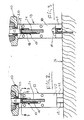
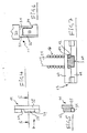
- the driving tool shown in Fig. 1 has in a conventional manner a housing 10 in which a pneumatically driven piston is guided in a cylinder.
- a driving plunger 11 is connected to the piston and is guided in a driving channel 12 of a mouth tool 13.
- a magazine 15 is fastened to the housing 10 by means of a handle part 14, which at the same time forms a compressed air reservoir. In the front area it is attached to the mouth tool 13.
- a fastener rod 16 is arranged, with the help of a not shown advance bers is advanced in the direction of drive channel 12.
- the fastener strip 16 consists of U-shaped fasteners 17 (see Figures 2 and 3), which consist of a long leg 18 and a short leg 19, which are connected to one another via a web 20.
- the fastening means 17 resemble a conventional U-clamp, of which one leg is considerably shortened, so that the portion near the web has the shape of a hook or a crutch.
- hooks can be lined up to form a strip or rod and can be stored in the manner shown. They can therefore, as is the case with U-clips, ride on a guide rail 21 and be advanced on the guide rail 21 with the aid of the pusher, not shown.
- the longer leg 18 is preferably pointed.
- the shorter leg can also be provided with a point.
- the previously described parts of the driving tool according to FIG. 1 are known per se, also a sensing element 22 which is slidably mounted on the muzzle tool 13 and which normally projects beyond the lower end of the muzzle tool and is coupled to the release lever 24 for the driving tool via a lever linkage 23. If the mouth tool 13 is placed on a workpiece, for example the workpiece 26 in 2 or 3, the sensing element 22 is pushed upwards and actuates the linkage 23. As a result, the release lever 24 is unlocked.
- the driving plunger 11 has a rectangular cross section in the upper region, as can be seen at 30.
- the width on both sides decreases by a certain amount, which - in the drawing example - corresponds to approximately half the diameter of the wire for the fastening means.
- a shoulder 31 is formed on the rear side.
- an L-shaped raised section 32 which forms an upper contact surface 33 for a fastener web 20.
- the upper part of the transverse web of the L-shaped section 32 forms a contact surface 34 for the free end of the shorter leg 19 of the fastening means 17.
- the longitudinal web of the raised section 32 is moved somewhat back in this area compared to the plunger section 35, on both sides, while the crosspiece of the raised portion 32 extends to the right side to the right edge of the upper portion 30 of the plunger 11. Due to the contour of the plunger 11 in the lower region, a recess is formed which portion of the fastener 17 near the web, as shown in FIGS. 2 and 3. In the top dead center position of the plunger 11, this recess is arranged such that the foremost fastening means 17 can be received.
- the shoulder 31 is therefore located somewhat above the upper side of the webs of the fastener strip 16.
- the legs of the fastener are guided on all sides by the raised section 32 on the inside and are supported in the web section and at the end of the shorter leg, as can also be seen in FIG. 7.
- the mouth tool 13 consists of two plates 40, 41 lying opposite one another, which form the drive-in channel 12 by means of channel-shaped recesses, as shown in FIG. 7. It goes without saying that the drive-in channel must be designed such that it guides the drive-in tappet 11 on all sides together with the fastening means received in the recess. As can be seen from FIG. 3, the portion of the fastening means 17 near the web is guided during the entire driving-in process.
- the upper region of the longer leg 18 lies between the associated wall of the drive channel 12 and the facing guide side of the raised portion 32.
- the web 22 lies between the shoulder 31 and the top 33 of the raised portion 32.
- the shorter leg 19 is between the associated channel wall and the associated outer side of the longitudinal web of the raised portion 32, wherein the free end can be supported on the contact surface 34.
- the portion of the fastener close to the web therefore retains its shape, even if the longer leg is driven into a particularly hard workpiece 26.
- the rear plate 41 of the muzzle tool 13 is shorter than the plate 41, and thus ends at a distance from the free end of the muzzle tool.
- the drive-in channel 12 is free up to the level of the shoulder 31 when the plunger 11 is in its bottom dead center position (see FIG. 3).
- the fastener 17 driven into the workpiece 26 can therefore be freed from it by advancing the driving tool.
Landscapes
- Engineering & Computer Science (AREA)
- Mechanical Engineering (AREA)
- General Engineering & Computer Science (AREA)
- Physics & Mathematics (AREA)
- Fluid Mechanics (AREA)
- Portable Nailing Machines And Staplers (AREA)
Priority Applications (1)
| Application Number | Priority Date | Filing Date | Title |
|---|---|---|---|
| EP87116366A EP0314831A1 (fr) | 1987-11-06 | 1987-11-06 | Barre de moyens de fixation et appareil de clouage pour clouer les moyens de fixation de ladite barre |
Applications Claiming Priority (1)
| Application Number | Priority Date | Filing Date | Title |
|---|---|---|---|
| EP87116366A EP0314831A1 (fr) | 1987-11-06 | 1987-11-06 | Barre de moyens de fixation et appareil de clouage pour clouer les moyens de fixation de ladite barre |
Publications (1)
| Publication Number | Publication Date |
|---|---|
| EP0314831A1 true EP0314831A1 (fr) | 1989-05-10 |
Family
ID=8197424
Family Applications (1)
| Application Number | Title | Priority Date | Filing Date |
|---|---|---|---|
| EP87116366A Withdrawn EP0314831A1 (fr) | 1987-11-06 | 1987-11-06 | Barre de moyens de fixation et appareil de clouage pour clouer les moyens de fixation de ladite barre |
Country Status (1)
| Country | Link |
|---|---|
| EP (1) | EP0314831A1 (fr) |
Cited By (3)
| Publication number | Priority date | Publication date | Assignee | Title |
|---|---|---|---|---|
| WO1999020079A1 (fr) * | 1997-10-15 | 1999-04-22 | Emerson Electric Co. | Agrafe microfil destinee a maintenir en place le composant resistif d'un element chauffant |
| EP1514647A1 (fr) * | 2003-09-09 | 2005-03-16 | Illinois Tool Works Inc. | Nez d'outil pour pistolet à clouer et pistolet à clouer pour maintenir une pièce à distance d'un substrat et procédé pour maintenir une pièce |
| EP1514977A1 (fr) * | 2003-09-09 | 2005-03-16 | Illinois Tool Works Inc. | Attache pour l'espacement d'un objet d'un substrat |
Citations (4)
| Publication number | Priority date | Publication date | Assignee | Title |
|---|---|---|---|---|
| US1816387A (en) * | 1925-12-10 | 1931-07-28 | Menninger Elmore William | Furring construction |
| US2589491A (en) * | 1946-07-31 | 1952-03-18 | Charles B Goodstein | Staple setting apparatus and method |
| US3279672A (en) * | 1964-06-25 | 1966-10-18 | Powers Wire Products Company I | Fastener driving and furring tool for stucco-netting and the like |
| FR2368341A1 (fr) * | 1976-10-25 | 1978-05-19 | Roy Christian | Outil manuel permettant de fixer un clou ou une agrafe |
-
1987
- 1987-11-06 EP EP87116366A patent/EP0314831A1/fr not_active Withdrawn
Patent Citations (4)
| Publication number | Priority date | Publication date | Assignee | Title |
|---|---|---|---|---|
| US1816387A (en) * | 1925-12-10 | 1931-07-28 | Menninger Elmore William | Furring construction |
| US2589491A (en) * | 1946-07-31 | 1952-03-18 | Charles B Goodstein | Staple setting apparatus and method |
| US3279672A (en) * | 1964-06-25 | 1966-10-18 | Powers Wire Products Company I | Fastener driving and furring tool for stucco-netting and the like |
| FR2368341A1 (fr) * | 1976-10-25 | 1978-05-19 | Roy Christian | Outil manuel permettant de fixer un clou ou une agrafe |
Cited By (5)
| Publication number | Priority date | Publication date | Assignee | Title |
|---|---|---|---|---|
| WO1999020079A1 (fr) * | 1997-10-15 | 1999-04-22 | Emerson Electric Co. | Agrafe microfil destinee a maintenir en place le composant resistif d'un element chauffant |
| EP1514647A1 (fr) * | 2003-09-09 | 2005-03-16 | Illinois Tool Works Inc. | Nez d'outil pour pistolet à clouer et pistolet à clouer pour maintenir une pièce à distance d'un substrat et procédé pour maintenir une pièce |
| EP1514977A1 (fr) * | 2003-09-09 | 2005-03-16 | Illinois Tool Works Inc. | Attache pour l'espacement d'un objet d'un substrat |
| US6986448B2 (en) | 2003-09-09 | 2006-01-17 | Illinois Tool Works Inc. | Fastener driving tool for spacing object from substrate |
| AU2004208719B2 (en) * | 2003-09-09 | 2007-03-22 | Illinois Tool Works Inc. | Fastener for spacing object from substrate |
Similar Documents
| Publication | Publication Date | Title |
|---|---|---|
| DE2704224C3 (de) | Klammermagazin zum Ansetzen an ein Heftwerkzeug | |
| DE2712294A1 (de) | Vorrichtung an werkzeugen zum eintreiben von befestigungsmitteln | |
| DE2403611A1 (de) | Geraet zum eintrieben flacher befestigungselemente wie drahtklammern oder stifte | |
| DE2926821A1 (de) | Geraet zum eintreiben von befestigungsmitteln | |
| EP2051835A1 (fr) | Dispositif de clouage | |
| EP0510351B1 (fr) | Outil d'enfoncement d'attaches | |
| DE1650999A1 (de) | Loesbare Befestigung zweier Teile,z.B. einer Verkleidungsplatte an einer anderen Platte oder Wand | |
| DE60125729T2 (de) | Nagelgerät für nägel und heftklammern mit elastischer führungsvorrichtung für den nagel in der eintriebposition | |
| DE3506421A1 (de) | Nageleintreibgeraet mit im querschnitt zentralsymmetrischem treiber | |
| EP1245860A1 (fr) | Dispositif de fixation d'agrafes de jonction de courroie à des courroies transporteuses | |
| DE3048465A1 (de) | Werkzeug zum eintreiben von heftnaegeln oder heftklammern in einen rahmen, speziell bilderrahmen | |
| DE102013011804A1 (de) | Klammerstab | |
| EP0472760A1 (fr) | Clôture | |
| DE2453646A1 (de) | Lademagazin fuer heftmaschinen | |
| DE3522140C2 (fr) | ||
| DE2240233A1 (de) | Vorrichtung zum zufuehren von unterlagscheiben | |
| DE2163557B2 (de) | Magazin für ein Gerät zum Eintreiben von Befestigungsmitteln | |
| EP0472759A1 (fr) | Clôture | |
| DE254536C (fr) | ||
| DE61914C (de) | Maschine zur Herstellung von Kisten | |
| DE4491676B4 (de) | Tragbare Befestigungselement-Eintreibvorrichtung | |
| CH699287A2 (de) | Vorrichtung zur befestigung von drahtwerk als rankhilfe für weinreben und andere pflanzen. | |
| DE2537460A1 (de) | Stiftartiges befestigungsmittel | |
| AT213005B (de) | Nagelartig einschlagbarer Fachbrett-Träger für Schränke od. dgl. | |
| DE3112129A1 (de) | Befestigung von zaeunen |
Legal Events
| Date | Code | Title | Description |
|---|---|---|---|
| PUAI | Public reference made under article 153(3) epc to a published international application that has entered the european phase |
Free format text: ORIGINAL CODE: 0009012 |
|
| AK | Designated contracting states |
Kind code of ref document: A1 Designated state(s): AT CH DE ES FR GR IT LI |
|
| 17P | Request for examination filed |
Effective date: 19891102 |
|
| 17Q | First examination report despatched |
Effective date: 19910422 |
|
| STAA | Information on the status of an ep patent application or granted ep patent |
Free format text: STATUS: THE APPLICATION IS DEEMED TO BE WITHDRAWN |
|
| 18D | Application deemed to be withdrawn |
Effective date: 19910903 |
|
| RIN1 | Information on inventor provided before grant (corrected) |
Inventor name: ALBRECHT, KLAUS Inventor name: KUCK, MANFRED |