EP0314860A1 - Konstruktion eines Blechpaketes für Ständer und Läufer einer dynamo-elektrischen Maschine - Google Patents
Konstruktion eines Blechpaketes für Ständer und Läufer einer dynamo-elektrischen Maschine Download PDFInfo
- Publication number
- EP0314860A1 EP0314860A1 EP88104718A EP88104718A EP0314860A1 EP 0314860 A1 EP0314860 A1 EP 0314860A1 EP 88104718 A EP88104718 A EP 88104718A EP 88104718 A EP88104718 A EP 88104718A EP 0314860 A1 EP0314860 A1 EP 0314860A1
- Authority
- EP
- European Patent Office
- Prior art keywords
- stator
- rotor
- plate
- slots
- slot
- Prior art date
- Legal status (The legal status is an assumption and is not a legal conclusion. Google has not performed a legal analysis and makes no representation as to the accuracy of the status listed.)
- Granted
Links
- 238000003475 lamination Methods 0.000 title claims abstract description 98
- 238000010276 construction Methods 0.000 title description 12
- 238000004804 winding Methods 0.000 claims abstract description 34
- 230000004907 flux Effects 0.000 claims abstract description 28
- 239000003302 ferromagnetic material Substances 0.000 claims description 13
- 239000004020 conductor Substances 0.000 claims description 9
- 230000005291 magnetic effect Effects 0.000 claims description 8
- CYTYCFOTNPOANT-UHFFFAOYSA-N Perchloroethylene Chemical compound ClC(Cl)=C(Cl)Cl CYTYCFOTNPOANT-UHFFFAOYSA-N 0.000 description 5
- 239000000463 material Substances 0.000 description 5
- 230000006872 improvement Effects 0.000 description 3
- RYGMFSIKBFXOCR-UHFFFAOYSA-N Copper Chemical compound [Cu] RYGMFSIKBFXOCR-UHFFFAOYSA-N 0.000 description 2
- XEEYBQQBJWHFJM-UHFFFAOYSA-N Iron Chemical compound [Fe] XEEYBQQBJWHFJM-UHFFFAOYSA-N 0.000 description 2
- 230000008901 benefit Effects 0.000 description 2
- 229910052802 copper Inorganic materials 0.000 description 2
- 239000010949 copper Substances 0.000 description 2
- 230000006698 induction Effects 0.000 description 2
- 238000004519 manufacturing process Methods 0.000 description 2
- 229910000831 Steel Inorganic materials 0.000 description 1
- 230000002411 adverse Effects 0.000 description 1
- 230000004323 axial length Effects 0.000 description 1
- 230000000052 comparative effect Effects 0.000 description 1
- 238000001816 cooling Methods 0.000 description 1
- 238000013461 design Methods 0.000 description 1
- 238000009826 distribution Methods 0.000 description 1
- 238000010348 incorporation Methods 0.000 description 1
- 230000001939 inductive effect Effects 0.000 description 1
- 238000003780 insertion Methods 0.000 description 1
- 230000037431 insertion Effects 0.000 description 1
- 230000003993 interaction Effects 0.000 description 1
- 229910052742 iron Inorganic materials 0.000 description 1
- 238000003754 machining Methods 0.000 description 1
- 239000003550 marker Substances 0.000 description 1
- 238000005259 measurement Methods 0.000 description 1
- 238000000034 method Methods 0.000 description 1
- 238000012986 modification Methods 0.000 description 1
- 230000004048 modification Effects 0.000 description 1
- 239000010959 steel Substances 0.000 description 1
Images


Classifications
-
- H—ELECTRICITY
- H02—GENERATION; CONVERSION OR DISTRIBUTION OF ELECTRIC POWER
- H02K—DYNAMO-ELECTRIC MACHINES
- H02K1/00—Details of the magnetic circuit
- H02K1/06—Details of the magnetic circuit characterised by the shape, form or construction
- H02K1/12—Stationary parts of the magnetic circuit
- H02K1/16—Stator cores with slots for windings
- H02K1/165—Shape, form or location of the slots
-
- H—ELECTRICITY
- H02—GENERATION; CONVERSION OR DISTRIBUTION OF ELECTRIC POWER
- H02K—DYNAMO-ELECTRIC MACHINES
- H02K17/00—Asynchronous induction motors; Asynchronous induction generators
- H02K17/02—Asynchronous induction motors
- H02K17/16—Asynchronous induction motors having rotors with internally short-circuited windings, e.g. cage rotors
- H02K17/18—Asynchronous induction motors having rotors with internally short-circuited windings, e.g. cage rotors having double-cage or multiple-cage rotors
-
- H—ELECTRICITY
- H02—GENERATION; CONVERSION OR DISTRIBUTION OF ELECTRIC POWER
- H02K—DYNAMO-ELECTRIC MACHINES
- H02K17/00—Asynchronous induction motors; Asynchronous induction generators
- H02K17/02—Asynchronous induction motors
- H02K17/16—Asynchronous induction motors having rotors with internally short-circuited windings, e.g. cage rotors
- H02K17/20—Asynchronous induction motors having rotors with internally short-circuited windings, e.g. cage rotors having deep-bar rotors
Definitions
- the present invention relates generally to dynamo-electric machines with laminated rotors and stator cores, and more particularly to lamination constructions in which stator teeth and rotor slots have relative dimensions such as to provide improved output for a given size machine.
- Rotors formed of a stack of laminations having closed slots equally spaced from one another about the periphery of each lamination are known from, for example, U.S. Patents 2,794,138 (May 28, 1957) and No. 3,401,280 (September 10, 1968), both having been assigned to the assignee of the present invention.
- Such rotors are ordinarily used in inductive AC motors, wherein conducting members which extend axially along the rotor through aligned slots of the stacked laminations interact with a rotating magnetic field created in an air gap between the outer circumference of the rotor and the inner circumference of the machine stator. Windings embedded in stator slots between radially inwardly projecting teeth of the stator, adjacent the air gap, are connected to the AC mains, and the stator winding conductors pass through a certain order of the stator slots so as to cause magnetic flux in the air gap to rotate in synchronism with the frequency of the AC mains.
- each of the rotor slots is constricted between its top and bottom parts in the radial direction, to form a so-called neck portion of the slot.
- Such closed slot rotors ordinarily have the slots in each of the rotor laminations formed with an inverted V shaped edge at the upper boundary of the top part of the slot, with the center of the V creating a narrow bridge part between the upper boundary of the slot and the outer circumference of the lamination. Understandably, such bridge part presents difficulties in machining of the closed slots at the peripheries of the rotor laminations.
- An object of the invention is to provide a dynamo-electric machine construction in which improvement is obtained through a greater amount of lamination material for both the stator core and the rotor of the machine, with less winding conductors than used previously.
- Another object of the invention is to provide a dynamo-electric machine in which leakage flux from end turns of a winding embedded in slots of a laminated core, is substantially reduced.
- a further object of the invention is to provide a dynamo-electric machine which can achieve a greater horsepower to volume ratio than that previously obtained.
- Another object of the invention is to provide a closed slot rotor lamination which can be manufactured without imposing costly production procedures.
- a dynamo-electric machine includes a generally cylindrical casing and a stator core fixed in the casing and comprised of stator plate laminations.
- a stator winding is embedded in slots extending from the bore of the stator core and a rotor is supported in the bore, the rotor comprising rotor plate laminations with conductor means for interacting with a magnetic field produced in an air gap between the outer periphery of the rotor and the inner periphery of the stator core.
- Each of the stator plate laminations is comprised of a flat annular plate of ferro-magnetic material with a pre-selected outer diameter and a generally circular inner opening of a pre-selected inner diameter.
- the stator plate lamination has a number of equally circumferentially spaced slots extending radially outwardly from the bore to an intermediate circumference of the plate to establish teeth between the slots.
- a tooth portion is defined by the teeth between the intermediate circumference and the bore, and a yoke portion is defined between the intermediate circumference and the outer periphery of the stator lamination plate.
- Each of the rotor plate laminations is comprised of a flat circular plate of ferro-magnetic material with a number of equally circumferentially spaced closed slots extending radially near the outer periphery of the plate.
- Each of the slots is defined by a semi-circular or curvilinear edge at an upper slot region adjacent to the outer periphery of the plate and symmetrical about a radial center line. End points of the curvilinear edge are coincident with ends of spaced substantially parallel sides of the slot, which sides extend equal distances toward the center of the plate to define with the curvilinear edge a top part of the slot.
- the top part opens into a larger bottom part of the slot, which is substantially triangularly-shaped and symmetrical about the radial center line.
- stator teeth are sufficiently wide relative to the area of the stator slot openings so that the ratio of flux density in the tooth portion to flux density in the yoke portion is optimized for a given n pole operating configuration for the stator winding.
- Fig. 1 shows a side view, in section, of a dynamo-electric machine 10 in which the present invention may be embodied.
- a front view of the machine 10 is shown in Fig. 2.
- the machine 10 includes a generally cylindrical outer casing 12, and a generally cylindrical stator 14 fixed coaxially within the outer casing 12 and having a coaxial bore 16.
- a rotor 18 is supported by suitable bearings 20a, 20b at the front and the back of casing 12, to extend axially within the bore 16 and for rotational movement about the bore axis.
- a shaft part 22 of the rotor 18 extends axially from a front end shield 24 of the machine 10, and has a key 26 projecting radially outward from a recess cut axially a certain distance from the front of the shaft part 22. Key 26 serves to lock the shaft part 22 into a corresponding key way cut in a load member (not shown), e.g., a fan, to which rotational motive power is to be supplied by the machine 10.
- a load member not shown
- a back end shield 28 (Fig. 1) together with the casing 12 and the front end shield 24 serve to contain and protect stator 14, rotor 18 and associated conductive windings.
- a machine cooling fan 30 is mounted on a rotor stub part 32 which extends outside the back end shield 28, and directs an air current flow over the casing.
- the stator 14 is comprised of a stack of plate laminations 34 of ferromagnetic material.
- the laminations 34 are stacked face-to-face and are held together to form a core by any of various means well known in the art.
- a number (S1) of slots extend along the axial length of the stator 14, and project radially from the bore 16. These slots accommodate stator windings that have end turns 36, parts of which are shown in Fig. 1. Details of individual plate laminations embodying the invention in a preferred form are given below.
- the shaft part 22 of the rotor 18 extends axially from the machine casing or housing 12 and has a stack of rotor laminations 40 fixed coaxially on the shaft part 22 intermediate the front and back bearings 20a, 20b.
- Sets of conductive bars 42 pass through a number (S2) of axially extending slots formed in the rotor 18 near the outer periphery of each of the laminations 40.
- the bars 42 are shorted to one another at the axial ends 44a, 44b of the rotor lamination stack by a set of end rings 46a, 46b.
- stator winding end turns 36 at axial end faces 48a, 48b, of the stator 14 are a source of stator flux leakage i.e. magnetic flux produced by the stator winding which does not interface with the conductive bars 42 in the rotor laminations 40.
- stator flux leakage does not contribute to the resultant torque exerted on the rotor 18 when the stator winding or windings are energized, such flux leakage adversely affects the operating efficiency of the machine 10. It will therefore be understood that any means by which potential sources of stator flux leakage can be reduced or eliminated, are of great importance in dynamo-electric machine construction.
- the present invention aims to provide a dynamo-electric machine construction which conforms with industry standards, particularly with respect to the so-called 180 and 210 frame size constructions. It will be understood, however, that although dimensions for machine laminations disclosed herein will apply to the 180 and 210 frame sizes, the invention can be embodied with advantage in machines of various sizes and proportions.
- a stator plate lamination 34 for a 180 or 210 frame size comprises a flat annular plate of ferromagnetic material having an outer diameter "OD" according to the tabular value of Fig. 7, and a generally circular bore opening 50 of a certain inner diameter "ID".
- the lamination 34 is a stator lamination so that the bore opening 50 defines one boundary for a stator-rotor air gap and a bore for receiving the rotor.
- the slot openings 52 are formed to contain one or more stator windings which extend axially through the stator 14 when like ones of the plates 34 are stacked face-to-face with corresponding slot openings 52 substantially aligned to communicate with one another.
- n 2, or 4, or 6, etc.
- the annular plate 34 in Fig. 3 includes a tooth portion 58 defined by the teeth 56 between the intermediate circumference 54 and the air gap periphery.
- the remainder of the plate 34 is continuous between the intermediate circumference 54 and the outer periphery 59 to define a yoke portion 60 of the plate 34.
- Fig. 4 is an enlarged view of a part of the plate laminations 34 in Fig. 3. Specifically, a single slot opening 52 is shown surrounded by adjacent teeth 56. Lip parts 61 project circumferentially toward one another from the adjacent teeth 56, to define a mouth 62 of width W10 of the slot opening 52. As is known, mouth 62 should be sufficiently wide to allow individual conductors 64 forming the stator winding to be inserted in the opening 52 through the mouth 62 when the machine 10 is assembled. The lip parts 61 act to seat a winding closure wedge 66 which holds the conductors 64 of the stator winding firmly in place within the stator slots formed by the openings 52.
- an insulating winding separator 68 may be positioned as shown in Fig. 4 in the stator slots, and an insulating film 70 positioned against the walls of the stator slots prevents arcing or short circuiting of individual conductors 64 with the material of which the laminations 34 are made.
- the teeth 56 are sufficiently wide relative to the area of the slot openings 52 so that the ratio of flux density in the tooth portion 58 (Fig. 3) (BT1) to flux density in the yoke portion 60 (BY1) when the stator windings are energized, is substantially optimized for a given n pole operation of the stator windings.
- the actual number (S1) of slot openings is not critical.
- the lamination plate 34 in Fig. 3 is shown with 24 slots and has the dimensions in Fig. 7 suitable for incorporation in a 180 or 210 frame size machine.
- An underlying concept of the present invention is to utilize maximum amounts of ferromagnetic material (e.g., iron) for the laminations 34 and minimum amounts of winding conductors, e.g., the individual conductors 64 in a dynamo-electric machine having a desired power handling capability.
- ferromagnetic material e.g., iron
- the ratios of the tooth portions 58 to yoke portions 60 for the laminations 34 substantially differ from known constructions, as does the ratio of inner diameter to outer diameter of the laminations 34.
- the lip parts 61 thus become very small relative to the known structures as a consequence of the relatively wide teeth 56.
- Use of less winding material also results in smaller end turns (e.g., the stator end turns 36) at the end faces to the stator lamination stack, and, thus, undesired flux leakage is significantly reduced from that in the prior constructions.
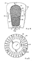
- Fig. 5 is a plan view of a rotor lamination for a 180 or 210 frame size, according to the present invention.
- the rotor lamination is formed of a flat circular plate 70 of ferromagnetic material.
- Slots 72 are formed to contain conductive bars 42 (Fig. 1) which extend substantially parallel to the axis of the rotor 18 when the plates 70 are stacked face-to-face with the corresponding slots 72 substantially aligned to communicate with one another.
- Each of the slots 72 is substantially rectangular through an upper slot region 74, as shown in Figs 5 and 6.
- a curvilinear or semi-circular edge 76 of each slot 72, adjacent the outer circumference 78 of the plate, is symmetrical about the radial center line of the slot 72.
- the curvilinear edge has a semi-circular shape with radius of between 0.625 mm. and 0.750 mm.
- End points 80a, 80b, of the semi-circular edge 76 are coincident with ends of spaced substantially parallel edges 82a, 82b of the plate 70.
- the edges 82a, 82b extend equal distances L1 in the direction towards the center C of the rotor lamination plate 70.
- a bridge area 84 of the plate 70 is thus formed between the edge 76 and the outer circumference 78.
- each slot 72 defined by the edge 76 and the parallel edges 82a, 82b opens into a bottom part of the slot which is substantially triangularly shaped and symmetrical about the radial center line.
- opposite ends of the edges 82a, 82b are curved continuously at a first radius R1 to diverge outward from the center line over an arc of approximately 90 degrees, and then curve toward the center C of the plate 70 at a second radius R2 over another approximately 90 degree arc, as shown in Fig. 6, to a set of points 84a, 84b.
- punched diameter means “as punched” by a punch press and does not contemplate finishing operations for establishing air gap defining finished surfaces.
- a rotor lamination plate diameter of about “102 mm.” would be inclusive of a lamination plate having a nominal, as punched, diameter of 102 mm., as well as a rotor lamination stacked within a finished rotor and having a finished outer diameter somewhat less than 102 mm. so that a proper air gap will be maintained between the rotor and stator core of the machine 10.
- Table 1 shows preferred values of dimensions for both the stator lamination plate 34 and the rotor lamination plate 70 for a 2-pole, 3-phase dynamo-electric machine 10 constructed according to the NEMA Standard 180 frame.
- Table 2 gives preferred values for the plates 34, 70 in a 2-pole, 3-phase NEMA Standard 210 frame.
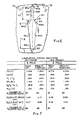
- Fig. 7 is a table in which physical constants, relationships, and ratios associated with the laminations dimensioned according to the invention in Tables 1 and 2, are compared with the closest known prior configurations, for 2 pole AC induction motors with NEMA 180 and 210 sizes. For comparison with known values, the specific measurements have been converted into inches. Included in Fig. 7 is a value of the net and gross area of the slots in the stator multiplied by the number (S1) of slots in the stator. The net slot area (ASLOT-NET) equals the gross slot area (ASLOT-GROSS, see Fig. 3) less the area occupied by the slot liners, separators, and wedges and less the area at the mouth not available for insertion of windings (see Fig. 4).
- the teeth width of the present laminations is generally greater than in prior laminations.
- the product of the number of rotor slots (S2) times the rotor tooth width (T2), divided by the product of the number of stator slots (S1) times the stator tooth width (T1) is, for the 180 and 210 sizes, preferably in the range of .825 to .90. In the examples of Fig. 7, the ratio in both cases is 0.850.
- Fig. 7 provides specific values for various ratios which are used to define the improved lamination.
- the ratio ID/OD represents the ratio of the inner diameter of the stator lamination to the outer diameter and gives an indication of the larger amount of ferromagnetic material than copper which is used in the present laminations.
- the value Btl/Byl can be used to represent the flux density in the tooth to the flux density in the yoke if it is assumed that the flux in the tooth and yoke is the same, which is a close approximation.
- This ratio gives an indication of tooth to yoke ratio.
- Machines employing laminations configured according to the invention have yielded greater horsepower to volume ratios when compared with known corresponding machines.
- Table 3 shows a comparison between percent efficiency and electromagnetic volume for 2 pole AC induction motors with laminations according to the present invention, and corresponding motors according to the prior art.
- the electromagnetic volume (OD)2L for machines according to the invention is generally lower than the volumes in the prior machines for about the same or even better efficiency.
- OD electromagnetic volume
- In the 10 HP hi efficiency motor a greater volume was used, but a rather substantial improvement in efficiency was achieved.
- For the hi efficiency 15 HP motor a cheaper steel was used which had greater losses so that even though there was a greater volume and only slight efficiency improvement, the cost saving was significant and could only be achieved using the present design.
- the use of wider or fatter teeth also produces a relatively higher flux density in the air gap between stator and rotor lamination stacks in machines according to the invention. Thus, more torque is produced from the rotor for a given machine size.
- Terminology used herein such as "generally cylindrical”, “essentially round”, and “annular”, with reference to or in connection with laminations (or plates) or structures made from such laminations (e.g. "cores”, stators, etc.), is inclusively descriptive of laminations, cores, etc, that do not have “true round” configurations due to the presence of peripherally located "key slots", marker notches, flats resulting from production processes (such as occur from zig-zag punch lines, for example), and so forth.
Landscapes
- Engineering & Computer Science (AREA)
- Power Engineering (AREA)
- Iron Core Of Rotating Electric Machines (AREA)
Applications Claiming Priority (2)
| Application Number | Priority Date | Filing Date | Title |
|---|---|---|---|
| US116303 | 1987-11-04 | ||
| US07/116,303 US4801832A (en) | 1987-11-04 | 1987-11-04 | Stator and rotor lamination construction for a dynamo-electric machine |
Publications (2)
| Publication Number | Publication Date |
|---|---|
| EP0314860A1 true EP0314860A1 (de) | 1989-05-10 |
| EP0314860B1 EP0314860B1 (de) | 1996-06-12 |
Family
ID=22366378
Family Applications (1)
| Application Number | Title | Priority Date | Filing Date |
|---|---|---|---|
| EP88104718A Expired - Lifetime EP0314860B1 (de) | 1987-11-04 | 1988-03-24 | Konstruktion eines Blechpaketes für Ständer und Läufer einer dynamo-elektrischen Maschine |
Country Status (6)
| Country | Link |
|---|---|
| US (2) | US4801832A (de) |
| EP (1) | EP0314860B1 (de) |
| JP (1) | JPH01129726A (de) |
| KR (1) | KR0139003B1 (de) |
| CA (1) | CA1312902C (de) |
| DE (1) | DE3855362T2 (de) |
Cited By (7)
| Publication number | Priority date | Publication date | Assignee | Title |
|---|---|---|---|---|
| WO1998034321A1 (en) * | 1997-02-03 | 1998-08-06 | Asea Brown Boveri Ab | A rotating electric machine |
| EP1223657A1 (de) * | 2001-01-16 | 2002-07-17 | Mitsubishi Denki Kabushiki Kaisha | Wechselstromgenerator für Fahrzeuge |
| ES2207370A1 (es) * | 2001-10-30 | 2004-05-16 | Gregorio Arias Juberias | Motor de induccion electromagnetica radial y variable sobre inducido de cobre solido con ranuras. |
| WO2005076435A1 (es) * | 2004-02-06 | 2005-08-18 | Gregorio Arias Juberias | Motor de inducción electromagnética |
| US7595577B2 (en) * | 2006-09-26 | 2009-09-29 | Jtekt Corporation | Brushless motor and electric power steering apparatus incorporating the same |
| EP2202871A3 (de) * | 2008-12-29 | 2014-04-09 | Tesla Motors, Inc. | Asynchronmotor mit verbesserte Drehmomentdichte |
| CN107112821A (zh) * | 2014-11-13 | 2017-08-29 | 罗伯特·博世有限公司 | 电机 |
Families Citing this family (85)
| Publication number | Priority date | Publication date | Assignee | Title |
|---|---|---|---|---|
| US5005281A (en) * | 1990-08-20 | 1991-04-09 | Dynamics Systems International Inc. | Method of making rotor and stator pole assemblies by stamping magnetic plate |
| JP2599061B2 (ja) * | 1991-12-13 | 1997-04-09 | オリエンタルモーター株式会社 | ステッピングモータ |
| JP3327431B2 (ja) * | 1994-08-31 | 2002-09-24 | オークマ株式会社 | 電動機 |
| US5744888A (en) * | 1995-02-03 | 1998-04-28 | Tiedtke-Buhling-Kinne & Partner | Multiphase and multipole electrical machine |
| US5644180A (en) | 1995-06-06 | 1997-07-01 | Itt Automotive Electrical Systems, Inc. | Rear motor bearing for worm gear drive motors |
| US5788341A (en) * | 1995-06-06 | 1998-08-04 | Itt Automotive Electrical Systems, Inc. | Vehicle brake |
| US5716279A (en) * | 1995-11-21 | 1998-02-10 | Itt Automotive Electrical Systems, Inc. | Apparatus and method for coupling an output shaft of a motor to a secondary shaft |
| US6304018B1 (en) | 1995-11-21 | 2001-10-16 | Valeo Electrical Systems, Inc. | Externally-wound stator with improved magnetic transition |
| WO1997020376A1 (en) * | 1995-11-28 | 1997-06-05 | Itt Automotive Electrical Systems, Inc. | Motor having recessed area in motor case for retaining motor shaft bearing therein |
| US5829305A (en) * | 1996-03-18 | 1998-11-03 | Itt Automotive Electrical Systems, Inc. | Vehicle window drive system and method |
| US6972505B1 (en) | 1996-05-29 | 2005-12-06 | Abb | Rotating electrical machine having high-voltage stator winding and elongated support devices supporting the winding and method for manufacturing the same |
| SE9602079D0 (sv) | 1996-05-29 | 1996-05-29 | Asea Brown Boveri | Roterande elektriska maskiner med magnetkrets för hög spänning och ett förfarande för tillverkning av densamma |
| AU718706B2 (en) | 1996-05-29 | 2000-04-20 | Abb Ab | A DC transformer/reactor |
| JP2000511338A (ja) | 1996-05-29 | 2000-08-29 | アセア ブラウン ボヴェリ エービー | 高圧巻線用導体および前記導体を含む巻線を備える回転電気機械 |
| SE510192C2 (sv) | 1996-05-29 | 1999-04-26 | Asea Brown Boveri | Förfarande och kopplingsarrangemang för att minska problem med tredjetonsströmmar som kan uppstå vid generator - och motordrift av växelströmsmaskiner kopplade till trefas distributions- eller transmissionsnät |
| CZ385998A3 (cs) | 1996-05-29 | 1999-06-16 | Abb Ab | Izolovaný vodič pro velmi vysoké napětí a způsob jeho výroby |
| SE509072C2 (sv) | 1996-11-04 | 1998-11-30 | Asea Brown Boveri | Anod, anodiseringsprocess, anodiserad tråd och användning av sådan tråd i en elektrisk anordning |
| SE510422C2 (sv) | 1996-11-04 | 1999-05-25 | Asea Brown Boveri | Magnetplåtkärna för elektriska maskiner |
| SE512917C2 (sv) | 1996-11-04 | 2000-06-05 | Abb Ab | Förfarande, anordning och kabelförare för lindning av en elektrisk maskin |
| SE515843C2 (sv) | 1996-11-04 | 2001-10-15 | Abb Ab | Axiell kylning av rotor |
| US5794326A (en) * | 1996-12-19 | 1998-08-18 | Itt Automotive Electrical Systems, Inc. | Removal of end play in electric motors |
| SE508544C2 (sv) | 1997-02-03 | 1998-10-12 | Asea Brown Boveri | Förfarande och anordning för montering av en stator -lindning bestående av en kabel. |
| SE9704412D0 (sv) | 1997-02-03 | 1997-11-28 | Asea Brown Boveri | Krafttransformator/reaktor |
| SE9704431D0 (sv) | 1997-02-03 | 1997-11-28 | Asea Brown Boveri | Effektreglering av synkronmaskin |
| SE9704423D0 (sv) | 1997-02-03 | 1997-11-28 | Asea Brown Boveri | Roterande elektrisk maskin med spolstöd |
| SE9704427D0 (sv) | 1997-02-03 | 1997-11-28 | Asea Brown Boveri | Infästningsanordning för elektriska roterande maskiner |
| SE9704421D0 (sv) | 1997-02-03 | 1997-11-28 | Asea Brown Boveri | Seriekompensering av elektrisk växelströmsmaskin |
| SE508543C2 (sv) | 1997-02-03 | 1998-10-12 | Asea Brown Boveri | Hasplingsanordning |
| SE9704413D0 (sv) | 1997-02-03 | 1997-11-28 | Asea Brown Boveri | Krafttransformator/reaktor |
| SE9704422D0 (sv) | 1997-02-03 | 1997-11-28 | Asea Brown Boveri | Ändplatta |
| SE510452C2 (sv) | 1997-02-03 | 1999-05-25 | Asea Brown Boveri | Transformator med spänningsregleringsorgan |
| SE513083C2 (sv) | 1997-09-30 | 2000-07-03 | Abb Ab | Synkronkompensatoranläggning jämte användning av dylik samt förfarande för faskompensation i ett högspänt kraftfält |
| SE513555C2 (sv) | 1997-11-27 | 2000-10-02 | Abb Ab | Förfarande för applicering av ett rörorgan i ett utrymme i en roterande elektrisk maskin och roterande elektrisk maskin enligt förfarandet |
| BR9815420A (pt) | 1997-11-28 | 2001-07-17 | Abb Ab | Método e dispositivo para controlar o fluxo magnético com um enrolamento auxiliar em uma máquina rotativa de alta voltagem de corrente alternada |
| GB2331858A (en) | 1997-11-28 | 1999-06-02 | Asea Brown Boveri | A wind power plant |
| GB2331853A (en) | 1997-11-28 | 1999-06-02 | Asea Brown Boveri | Transformer |
| GB2331867A (en) | 1997-11-28 | 1999-06-02 | Asea Brown Boveri | Power cable termination |
| JPH11215748A (ja) * | 1998-01-23 | 1999-08-06 | Toshiba Corp | 永久磁石形回転電機 |
| US6157109A (en) | 1998-02-10 | 2000-12-05 | Reliance Electric Technologies, Llc | Dynamoelectric machine with ferromagnetic end winding ring |
| KR19990013313A (ko) * | 1998-02-11 | 1999-02-25 | 이이수 | 무변출력 무정류자 직류전동기 |
| US6801421B1 (en) | 1998-09-29 | 2004-10-05 | Abb Ab | Switchable flux control for high power static electromagnetic devices |
| US6331760B1 (en) * | 1998-10-06 | 2001-12-18 | Mclane, Jr. Oscar B. | Capacitive induction motor and method |
| US6313559B1 (en) * | 1999-04-14 | 2001-11-06 | Denso Corporation | Stator arrangement of rotary electric machine |
| SE516002C2 (sv) | 2000-03-01 | 2001-11-05 | Abb Ab | Roterande elektrisk maskin samt förfarande för framställning av en statorlindning |
| US6885273B2 (en) | 2000-03-30 | 2005-04-26 | Abb Ab | Induction devices with distributed air gaps |
| SE516442C2 (sv) | 2000-04-28 | 2002-01-15 | Abb Ab | Stationär induktionsmaskin och kabel därför |
| US6722015B2 (en) | 2001-08-11 | 2004-04-20 | General Electric Company | Assembly method for stamped and cupped laminations |
| US6847285B2 (en) * | 2001-08-13 | 2005-01-25 | General Electric Company | Interlock tabs for laminations |
| US20040012291A1 (en) * | 2002-07-19 | 2004-01-22 | Mclennan Paul S. | High density winding for electric motor |
| US7483519B2 (en) | 2003-12-23 | 2009-01-27 | At&T Intellectual Property I, L.P. | Caller controlled systems to suppress system to de-activate 911 indicator |
| US7355507B2 (en) * | 2003-12-23 | 2008-04-08 | At&T Delaware Intellectual Property, Inc. | 911 Emergency light |
| US7245704B2 (en) * | 2004-01-30 | 2007-07-17 | Bellsouth Intellectual Property Corporation | Automated third party call activated when 911 dialed |
| US7620156B2 (en) * | 2006-06-06 | 2009-11-17 | At&T Intellectual Property I, L.P. | Systems and methods for providing location signals/indicators when 911 dialed |
| US7937485B2 (en) * | 2004-08-31 | 2011-05-03 | At&T Intellectual Property I, L.P. | Streaming gateway |
| JP4848842B2 (ja) * | 2006-05-29 | 2011-12-28 | 株式会社ジェイテクト | ブラシレスモータ及び電動パワーステアリング装置 |
| US7692350B2 (en) * | 2007-02-28 | 2010-04-06 | Emerson Electric Co. | Horizontal axis washing machine having 4 pole 36 slot motor |
| JP5130777B2 (ja) * | 2007-04-23 | 2013-01-30 | 株式会社豊田自動織機 | ステータ |
| WO2009084251A1 (ja) * | 2007-12-27 | 2009-07-09 | Mitsubishi Electric Corporation | 誘導電動機の回転子及び誘導電動機及び圧縮機及び送風機及び空気調和機 |
| KR100921468B1 (ko) | 2008-01-21 | 2009-10-13 | 엘지전자 주식회사 | 모터 및 이를 포함하는 압축기 |
| KR101102748B1 (ko) * | 2008-01-25 | 2012-01-05 | 미쓰비시덴키 가부시키가이샤 | 유도 전동기 및 밀폐형 압축기 |
| DE102008015327B4 (de) * | 2008-03-20 | 2021-05-06 | Secop Gmbh | Rotor einer elektrischen Maschine und Motor mit einem derartigen Rotor |
| US7709992B2 (en) * | 2008-07-31 | 2010-05-04 | Emerson Electric Co. | Electric machine |
| MY156192A (en) * | 2008-08-05 | 2016-01-29 | Mitsubishi Electric Corp | Induction motor and hermetic compressor |
| US7893589B2 (en) * | 2008-09-03 | 2011-02-22 | Dayton-Phoenix Group, Inc. | AC-induction-motor rotor lamination having rotor slots |
| JP5490251B2 (ja) * | 2010-10-19 | 2014-05-14 | 三菱電機株式会社 | 誘導電動機の回転子及び誘導電動機及び圧縮機及び送風機及び空気調和機 |
| US9287759B2 (en) * | 2010-12-06 | 2016-03-15 | Mitsubishi Electric Corporation | Induction motor, compressor, air blower, and air conditioner |
| JP5591099B2 (ja) | 2010-12-28 | 2014-09-17 | 三菱電機株式会社 | 圧縮機および冷凍サイクル装置 |
| JP5722116B2 (ja) * | 2011-05-13 | 2015-05-20 | 日立オートモティブシステムズ株式会社 | 誘導回転電機 |
| CN202889143U (zh) * | 2011-12-28 | 2013-04-17 | 日本电产株式会社 | 单相感应马达 |
| CN104798294B (zh) * | 2012-11-22 | 2018-09-25 | 艾默生电气公司 | 电机、定子和压缩机,以及制造它们的方法 |
| JP2015186403A (ja) * | 2014-03-26 | 2015-10-22 | 住友重機械工業株式会社 | 誘導電動機 |
| EP2950424B1 (de) * | 2014-05-26 | 2020-11-04 | General Electric Technology GmbH | Kammer für Leiter von elektrischen Maschinen |
| CN105471132B (zh) * | 2014-05-29 | 2019-09-17 | 德昌电机(深圳)有限公司 | 电机用永久磁极及包括其的电机 |
| CN105471127B (zh) * | 2014-05-29 | 2019-02-05 | 德昌电机(深圳)有限公司 | 电机及电机用磁芯 |
| JP2015112011A (ja) * | 2015-02-10 | 2015-06-18 | 三菱電機株式会社 | 誘導電動機、圧縮機および冷凍サイクル装置 |
| CN104917345B (zh) * | 2015-06-18 | 2017-10-20 | 哈尔滨电气动力装备有限公司 | 低噪声36极三相异步电机的定转子冲片结构 |
| US10498280B1 (en) * | 2016-08-25 | 2019-12-03 | Apple Inc. | Electric motor with shielded phase windings |
| US10528023B2 (en) * | 2016-12-22 | 2020-01-07 | General Dynamics-OTS. Inc. | Electric motor drive system for low-voltage motor |
| CN107659008A (zh) * | 2017-11-13 | 2018-02-02 | 安徽美芝精密制造有限公司 | 压缩机的电机组件、压缩机及制冷设备 |
| FR3082375B1 (fr) * | 2018-06-07 | 2021-12-24 | Leroy Somer Moteurs | Stator de machine electrique tournante |
| FR3082374B1 (fr) | 2018-06-07 | 2020-05-29 | Moteurs Leroy-Somer | Stator de machine electrique tournante |
| JP2018139494A (ja) * | 2018-06-14 | 2018-09-06 | 住友重機械工業株式会社 | 誘導電動機 |
| US11742711B1 (en) | 2019-11-19 | 2023-08-29 | United States Of America As Represented By The Secretary Of The Air Force | Rotor for a high speed electrical machine |
| DE102020128431A1 (de) * | 2020-10-29 | 2022-05-05 | Dr. Ing. H.C. F. Porsche Aktiengesellschaft | Traktionsmotor für ein Fahrzeug |
| US12278532B2 (en) * | 2021-03-15 | 2025-04-15 | Anhui Meizhi Precision Manufacturing Co., Ltd. | Motor, compressor and refrigeration device |
Citations (4)
| Publication number | Priority date | Publication date | Assignee | Title |
|---|---|---|---|---|
| DE1176269B (de) * | 1961-04-08 | 1964-08-20 | Kurt Westphalen | Staenderblech fuer Ein- bis Dreiphasen-Wechselstrom-Motoren mit einem Aussen-durchmesser bis zu 200 mm |
| US3596121A (en) * | 1969-09-10 | 1971-07-27 | Robbins & Myers | Electric induction motor |
| DE2814745A1 (de) * | 1978-04-05 | 1979-10-11 | Siemens Ag | Stromverdraengungslaeufer |
| GB2020914A (en) * | 1978-05-10 | 1979-11-21 | Gen Electric | Laminated stators for dynamo-electric machines |
Family Cites Families (17)
| Publication number | Priority date | Publication date | Assignee | Title |
|---|---|---|---|---|
| US2125970A (en) * | 1936-01-06 | 1938-08-09 | Wagner Electric Corp | Method of making squirrel cage rotors |
| US2528154A (en) * | 1947-03-13 | 1950-10-31 | Westinghouse Electric Corp | Shrunk rotor for squirrel-cage motors |
| US2794138A (en) * | 1954-05-27 | 1957-05-28 | Gen Electric | Closed slot rotor punching |
| US2778964A (en) * | 1954-12-29 | 1957-01-22 | Gen Electric | Slot liner-closer for dynamoelectric machine core member |
| US3122667A (en) * | 1961-05-25 | 1964-02-25 | Gen Electric | Laminated magnetic core for use in an electric inductive device |
| US3401280A (en) * | 1966-03-01 | 1968-09-10 | Gen Electric | Fabricated squirrel cage rotor construction for electric motor and method of assembling the same |
| US3457445A (en) * | 1967-12-19 | 1969-07-22 | Gen Electric | Laminated rotors and stators with flux barriers for synchronous induction motors and method of making the same |
| JPS4926902B1 (de) * | 1970-12-24 | 1974-07-12 | ||
| JPS5523876B2 (de) * | 1972-06-09 | 1980-06-25 | ||
| FR2414816A1 (fr) * | 1978-01-11 | 1979-08-10 | Citroen Sa | Perfectionnements apportes aux moteurs electriques alimentes par un courant hache |
| US4365178A (en) * | 1981-06-08 | 1982-12-21 | General Electric Co. | Laminated rotor for a dynamoelectric machine with coolant passageways therein |
| US4566179A (en) * | 1983-05-19 | 1986-01-28 | Display Components, Inc. | Core element for electrodynamic rotary machine |
| US4585967A (en) * | 1983-10-21 | 1986-04-29 | General Electric Company | Rotor of AC dynamoelectric machine with improved cooling and stability and method of making the same |
| US4654552A (en) * | 1985-03-28 | 1987-03-31 | General Electric Company | Lanced strip and edgewise wound core |
| US4780635A (en) * | 1987-02-27 | 1988-10-25 | General Electric Company | Dynamo-electric machine lamination construction |
| US4788761A (en) * | 1987-06-26 | 1988-12-06 | General Electric Company | Method of assembling a core and method of assembling a slot liner |
| US4831301A (en) * | 1987-11-04 | 1989-05-16 | General Electric Company | Dynamo-electric machine lamination construction |
-
1987
- 1987-11-04 US US07/116,303 patent/US4801832A/en not_active Ceased
-
1988
- 1988-03-23 JP JP63067499A patent/JPH01129726A/ja active Pending
- 1988-03-24 DE DE3855362T patent/DE3855362T2/de not_active Expired - Lifetime
- 1988-03-24 EP EP88104718A patent/EP0314860B1/de not_active Expired - Lifetime
- 1988-04-06 KR KR1019880003807A patent/KR0139003B1/ko not_active Expired - Lifetime
- 1988-10-27 CA CA000581473A patent/CA1312902C/en not_active Expired - Lifetime
-
1990
- 1990-06-04 US US07/533,251 patent/USRE34667E/en not_active Expired - Lifetime
Patent Citations (4)
| Publication number | Priority date | Publication date | Assignee | Title |
|---|---|---|---|---|
| DE1176269B (de) * | 1961-04-08 | 1964-08-20 | Kurt Westphalen | Staenderblech fuer Ein- bis Dreiphasen-Wechselstrom-Motoren mit einem Aussen-durchmesser bis zu 200 mm |
| US3596121A (en) * | 1969-09-10 | 1971-07-27 | Robbins & Myers | Electric induction motor |
| DE2814745A1 (de) * | 1978-04-05 | 1979-10-11 | Siemens Ag | Stromverdraengungslaeufer |
| GB2020914A (en) * | 1978-05-10 | 1979-11-21 | Gen Electric | Laminated stators for dynamo-electric machines |
Cited By (11)
| Publication number | Priority date | Publication date | Assignee | Title |
|---|---|---|---|---|
| WO1998034321A1 (en) * | 1997-02-03 | 1998-08-06 | Asea Brown Boveri Ab | A rotating electric machine |
| EP1223657A1 (de) * | 2001-01-16 | 2002-07-17 | Mitsubishi Denki Kabushiki Kaisha | Wechselstromgenerator für Fahrzeuge |
| US6690099B2 (en) | 2001-01-16 | 2004-02-10 | Mitsubishi Denki Kabushiki Kaisha | Automotive alternator |
| ES2207370A1 (es) * | 2001-10-30 | 2004-05-16 | Gregorio Arias Juberias | Motor de induccion electromagnetica radial y variable sobre inducido de cobre solido con ranuras. |
| WO2005076435A1 (es) * | 2004-02-06 | 2005-08-18 | Gregorio Arias Juberias | Motor de inducción electromagnética |
| US7595577B2 (en) * | 2006-09-26 | 2009-09-29 | Jtekt Corporation | Brushless motor and electric power steering apparatus incorporating the same |
| EP2202871A3 (de) * | 2008-12-29 | 2014-04-09 | Tesla Motors, Inc. | Asynchronmotor mit verbesserte Drehmomentdichte |
| EP2202871B1 (de) | 2008-12-29 | 2015-05-06 | Tesla Motors, Inc. | Asynchronmotor mit verbesserte Drehmomentdichte |
| CN107112821A (zh) * | 2014-11-13 | 2017-08-29 | 罗伯特·博世有限公司 | 电机 |
| CN107112821B (zh) * | 2014-11-13 | 2019-05-28 | 罗伯特·博世有限公司 | 电机 |
| US10770956B2 (en) | 2014-11-13 | 2020-09-08 | Robert Bosch Gmbh | Electric machine |
Also Published As
| Publication number | Publication date |
|---|---|
| US4801832A (en) | 1989-01-31 |
| EP0314860B1 (de) | 1996-06-12 |
| KR890009044A (ko) | 1989-07-13 |
| JPH01129726A (ja) | 1989-05-23 |
| USRE34667E (en) | 1994-07-19 |
| CA1312902C (en) | 1993-01-19 |
| DE3855362D1 (de) | 1996-07-18 |
| DE3855362T2 (de) | 1997-02-06 |
| KR0139003B1 (ko) | 1998-06-15 |
Similar Documents
| Publication | Publication Date | Title |
|---|---|---|
| US4801832A (en) | Stator and rotor lamination construction for a dynamo-electric machine | |
| EP0280194B1 (de) | Blechkonstruktion für elektro-dynamische Maschine | |
| US4831301A (en) | Dynamo-electric machine lamination construction | |
| US4471252A (en) | Rotary dynamo electric machine with protection against demagnetization of low flux portion of permanent magnet poles | |
| CA2421716C (en) | Brush dc motors and ac commutator motor structures with concentrated windings | |
| US4388545A (en) | Rotor for a permanent magnet AC motor | |
| US4506181A (en) | Permanent magnet rotor with complete amortisseur | |
| US4403161A (en) | Permanent magnet rotor | |
| US4888513A (en) | Reluctance electric machine having a decreased cross section of rotor ferromagnetic material | |
| US3492520A (en) | Permanent magnet rotor | |
| EP0280192B1 (de) | Aufbau eines Läufers mit geschlossenen Nuten | |
| CN100502201C (zh) | 电机 | |
| Binns et al. | Permanent-magnet ac generators | |
| US4131814A (en) | Concentrated winding salient-pole shaded pole motors having multiple short circuited shading coils for each pole and methods of making same | |
| EP0280193B1 (de) | Zahnflankenkonstruktion eines Stators in einer elektro-dynamischen Maschine | |
| JPH0870541A (ja) | 永久磁石式回転電機 | |
| EP0352573A1 (de) | Läuferblechlamelle einer Synchronmaschine | |
| US3353046A (en) | Quiet-running electric motor | |
| CN112292803A (zh) | 转子及旋转电机 | |
| JPH05252675A (ja) | 発電機の動作特性を改善する方法及び発電機 | |
| CA1290002C (en) | Dynamo-electric machine lamination construction | |
| JPS6096145A (ja) | 同極励磁交流機 | |
| US3328616A (en) | Dynamoelectric induction machines | |
| JP2008518579A (ja) | 電気機械のための回転子−固定子構造 | |
| GB2110478A (en) | Dynamo electric machines |
Legal Events
| Date | Code | Title | Description |
|---|---|---|---|
| PUAI | Public reference made under article 153(3) epc to a published international application that has entered the european phase |
Free format text: ORIGINAL CODE: 0009012 |
|
| AK | Designated contracting states |
Kind code of ref document: A1 Designated state(s): DE FR GB IT NL SE |
|
| 17P | Request for examination filed |
Effective date: 19890928 |
|
| 17Q | First examination report despatched |
Effective date: 19910923 |
|
| GRAH | Despatch of communication of intention to grant a patent |
Free format text: ORIGINAL CODE: EPIDOS IGRA |
|
| GRAA | (expected) grant |
Free format text: ORIGINAL CODE: 0009210 |
|
| AK | Designated contracting states |
Kind code of ref document: B1 Designated state(s): DE FR GB IT NL SE |
|
| PG25 | Lapsed in a contracting state [announced via postgrant information from national office to epo] |
Ref country code: NL Free format text: LAPSE BECAUSE OF FAILURE TO SUBMIT A TRANSLATION OF THE DESCRIPTION OR TO PAY THE FEE WITHIN THE PRESCRIBED TIME-LIMIT Effective date: 19960612 |
|
| ET | Fr: translation filed | ||
| REF | Corresponds to: |
Ref document number: 3855362 Country of ref document: DE Date of ref document: 19960718 |
|
| ITF | It: translation for a ep patent filed | ||
| PG25 | Lapsed in a contracting state [announced via postgrant information from national office to epo] |
Ref country code: SE Effective date: 19960912 |
|
| NLV1 | Nl: lapsed or annulled due to failure to fulfill the requirements of art. 29p and 29m of the patents act | ||
| PLBE | No opposition filed within time limit |
Free format text: ORIGINAL CODE: 0009261 |
|
| STAA | Information on the status of an ep patent application or granted ep patent |
Free format text: STATUS: NO OPPOSITION FILED WITHIN TIME LIMIT |
|
| 26N | No opposition filed | ||
| REG | Reference to a national code |
Ref country code: GB Ref legal event code: IF02 |
|
| APAH | Appeal reference modified |
Free format text: ORIGINAL CODE: EPIDOSCREFNO |
|
| PGFP | Annual fee paid to national office [announced via postgrant information from national office to epo] |
Ref country code: GB Payment date: 20070327 Year of fee payment: 20 |
|
| PGFP | Annual fee paid to national office [announced via postgrant information from national office to epo] |
Ref country code: DE Payment date: 20070430 Year of fee payment: 20 |
|
| PGFP | Annual fee paid to national office [announced via postgrant information from national office to epo] |
Ref country code: IT Payment date: 20070523 Year of fee payment: 20 |
|
| PGFP | Annual fee paid to national office [announced via postgrant information from national office to epo] |
Ref country code: FR Payment date: 20070319 Year of fee payment: 20 |
|
| PG25 | Lapsed in a contracting state [announced via postgrant information from national office to epo] |
Ref country code: GB Free format text: LAPSE BECAUSE OF EXPIRATION OF PROTECTION Effective date: 20080323 |