EP0314937B1 - Capteur implantable du taux d'oxygène dans le sang et procédé d'emploi - Google Patents
Capteur implantable du taux d'oxygène dans le sang et procédé d'emploi Download PDFInfo
- Publication number
- EP0314937B1 EP0314937B1 EP19880116645 EP88116645A EP0314937B1 EP 0314937 B1 EP0314937 B1 EP 0314937B1 EP 19880116645 EP19880116645 EP 19880116645 EP 88116645 A EP88116645 A EP 88116645A EP 0314937 B1 EP0314937 B1 EP 0314937B1
- Authority
- EP
- European Patent Office
- Prior art keywords
- light
- sensor
- conductor
- emitting diode
- medical sensor
- Prior art date
- Legal status (The legal status is an assumption and is not a legal conclusion. Google has not performed a legal analysis and makes no representation as to the accuracy of the status listed.)
- Expired - Lifetime
Links
- 238000000034 method Methods 0.000 title claims description 35
- 239000008280 blood Substances 0.000 title claims description 32
- 210000004369 blood Anatomy 0.000 title claims description 32
- QVGXLLKOCUKJST-UHFFFAOYSA-N atomic oxygen Chemical compound [O] QVGXLLKOCUKJST-UHFFFAOYSA-N 0.000 title claims description 28
- 229910052760 oxygen Inorganic materials 0.000 title claims description 28
- 239000001301 oxygen Substances 0.000 title claims description 28
- 239000004020 conductor Substances 0.000 claims description 87
- RTAQQCXQSZGOHL-UHFFFAOYSA-N Titanium Chemical compound [Ti] RTAQQCXQSZGOHL-UHFFFAOYSA-N 0.000 claims description 28
- 239000010936 titanium Substances 0.000 claims description 26
- 229910052719 titanium Inorganic materials 0.000 claims description 26
- 239000000758 substrate Substances 0.000 claims description 25
- 229910052751 metal Inorganic materials 0.000 claims description 14
- 239000002184 metal Substances 0.000 claims description 13
- 239000011368 organic material Substances 0.000 claims description 11
- 210000001124 body fluid Anatomy 0.000 claims description 10
- 239000010839 body fluid Substances 0.000 claims description 10
- 230000008859 change Effects 0.000 claims description 8
- 239000000463 material Substances 0.000 claims description 8
- 238000012544 monitoring process Methods 0.000 claims description 6
- 239000005361 soda-lime glass Substances 0.000 claims description 6
- 238000012545 processing Methods 0.000 claims description 5
- 230000004936 stimulating effect Effects 0.000 claims description 4
- 239000000126 substance Substances 0.000 claims description 3
- 238000007789 sealing Methods 0.000 claims 4
- 208000023804 progressive myoclonic epilepsy type 7 Diseases 0.000 claims 1
- 239000012780 transparent material Substances 0.000 claims 1
- 239000011521 glass Substances 0.000 description 21
- 238000010586 diagram Methods 0.000 description 12
- 230000008569 process Effects 0.000 description 12
- 239000000919 ceramic Substances 0.000 description 10
- 238000005259 measurement Methods 0.000 description 8
- 239000012530 fluid Substances 0.000 description 7
- 238000003466 welding Methods 0.000 description 7
- 230000008901 benefit Effects 0.000 description 5
- 239000004642 Polyimide Substances 0.000 description 4
- 102100026827 Protein associated with UVRAG as autophagy enhancer Human genes 0.000 description 4
- 101710102978 Protein associated with UVRAG as autophagy enhancer Proteins 0.000 description 4
- 230000000747 cardiac effect Effects 0.000 description 4
- 239000011248 coating agent Substances 0.000 description 4
- 238000000576 coating method Methods 0.000 description 4
- 229920001721 polyimide Polymers 0.000 description 4
- 230000000638 stimulation Effects 0.000 description 4
- 239000004593 Epoxy Substances 0.000 description 3
- 238000013459 approach Methods 0.000 description 3
- 230000000903 blocking effect Effects 0.000 description 3
- 238000006243 chemical reaction Methods 0.000 description 3
- 230000008602 contraction Effects 0.000 description 3
- 238000009413 insulation Methods 0.000 description 3
- 230000003287 optical effect Effects 0.000 description 3
- 229920002635 polyurethane Polymers 0.000 description 3
- 239000004814 polyurethane Substances 0.000 description 3
- PNEYBMLMFCGWSK-UHFFFAOYSA-N aluminium oxide Inorganic materials [O-2].[O-2].[O-2].[Al+3].[Al+3] PNEYBMLMFCGWSK-UHFFFAOYSA-N 0.000 description 2
- 230000000694 effects Effects 0.000 description 2
- BASFCYQUMIYNBI-UHFFFAOYSA-N platinum Chemical compound [Pt] BASFCYQUMIYNBI-UHFFFAOYSA-N 0.000 description 2
- 230000035945 sensitivity Effects 0.000 description 2
- 230000035939 shock Effects 0.000 description 2
- 229920002379 silicone rubber Polymers 0.000 description 2
- 239000004945 silicone rubber Substances 0.000 description 2
- 229910001220 stainless steel Inorganic materials 0.000 description 2
- 239000010935 stainless steel Substances 0.000 description 2
- 230000035882 stress Effects 0.000 description 2
- 229910001369 Brass Inorganic materials 0.000 description 1
- 230000009471 action Effects 0.000 description 1
- 239000000853 adhesive Substances 0.000 description 1
- 230000001070 adhesive effect Effects 0.000 description 1
- 230000002411 adverse Effects 0.000 description 1
- 230000032683 aging Effects 0.000 description 1
- 230000009286 beneficial effect Effects 0.000 description 1
- 230000005540 biological transmission Effects 0.000 description 1
- 239000010951 brass Substances 0.000 description 1
- 239000002775 capsule Substances 0.000 description 1
- 229920001940 conductive polymer Polymers 0.000 description 1
- 238000007796 conventional method Methods 0.000 description 1
- 230000002596 correlated effect Effects 0.000 description 1
- 230000000875 corresponding effect Effects 0.000 description 1
- 230000007797 corrosion Effects 0.000 description 1
- 238000005260 corrosion Methods 0.000 description 1
- 238000013461 design Methods 0.000 description 1
- 238000011161 development Methods 0.000 description 1
- 230000018109 developmental process Effects 0.000 description 1
- 230000005496 eutectics Effects 0.000 description 1
- PCHJSUWPFVWCPO-UHFFFAOYSA-N gold Chemical compound [Au] PCHJSUWPFVWCPO-UHFFFAOYSA-N 0.000 description 1
- 239000010931 gold Substances 0.000 description 1
- 229910052737 gold Inorganic materials 0.000 description 1
- 238000010438 heat treatment Methods 0.000 description 1
- 238000002513 implantation Methods 0.000 description 1
- 230000001939 inductive effect Effects 0.000 description 1
- 239000011810 insulating material Substances 0.000 description 1
- 239000012774 insulation material Substances 0.000 description 1
- 210000003127 knee Anatomy 0.000 description 1
- 230000007774 longterm Effects 0.000 description 1
- 210000004072 lung Anatomy 0.000 description 1
- 238000004519 manufacturing process Methods 0.000 description 1
- 238000002844 melting Methods 0.000 description 1
- 230000008018 melting Effects 0.000 description 1
- 230000009972 noncorrosive effect Effects 0.000 description 1
- 230000000737 periodic effect Effects 0.000 description 1
- 238000001259 photo etching Methods 0.000 description 1
- 229910052697 platinum Inorganic materials 0.000 description 1
- 239000011527 polyurethane coating Substances 0.000 description 1
- 238000011165 process development Methods 0.000 description 1
- 238000003908 quality control method Methods 0.000 description 1
- 238000011084 recovery Methods 0.000 description 1
- 238000002310 reflectometry Methods 0.000 description 1
- 230000036279 refractory period Effects 0.000 description 1
- 230000002441 reversible effect Effects 0.000 description 1
- 238000005070 sampling Methods 0.000 description 1
- 238000000926 separation method Methods 0.000 description 1
- 238000002798 spectrophotometry method Methods 0.000 description 1
- 230000001360 synchronised effect Effects 0.000 description 1
- 238000012360 testing method Methods 0.000 description 1
- 238000003878 thermal aging Methods 0.000 description 1
- 239000010409 thin film Substances 0.000 description 1
- 230000008467 tissue growth Effects 0.000 description 1
- 238000012546 transfer Methods 0.000 description 1
- 210000000591 tricuspid valve Anatomy 0.000 description 1
- 210000003462 vein Anatomy 0.000 description 1
- 230000002861 ventricular Effects 0.000 description 1
Images




Classifications
-
- A—HUMAN NECESSITIES
- A61—MEDICAL OR VETERINARY SCIENCE; HYGIENE
- A61B—DIAGNOSIS; SURGERY; IDENTIFICATION
- A61B5/00—Measuring for diagnostic purposes; Identification of persons
- A61B5/145—Measuring characteristics of blood in vivo, e.g. gas concentration or pH-value ; Measuring characteristics of body fluids or tissues, e.g. interstitial fluid or cerebral tissue
- A61B5/1455—Measuring characteristics of blood in vivo, e.g. gas concentration or pH-value ; Measuring characteristics of body fluids or tissues, e.g. interstitial fluid or cerebral tissue using optical sensors, e.g. spectral photometrical oximeters
- A61B5/1459—Measuring characteristics of blood in vivo, e.g. gas concentration or pH-value ; Measuring characteristics of body fluids or tissues, e.g. interstitial fluid or cerebral tissue using optical sensors, e.g. spectral photometrical oximeters invasive, e.g. introduced into the body by a catheter
-
- A—HUMAN NECESSITIES
- A61—MEDICAL OR VETERINARY SCIENCE; HYGIENE
- A61N—ELECTROTHERAPY; MAGNETOTHERAPY; RADIATION THERAPY; ULTRASOUND THERAPY
- A61N1/00—Electrotherapy; Circuits therefor
- A61N1/18—Applying electric currents by contact electrodes
- A61N1/32—Applying electric currents by contact electrodes alternating or intermittent currents
- A61N1/36—Applying electric currents by contact electrodes alternating or intermittent currents for stimulation
- A61N1/362—Heart stimulators
- A61N1/365—Heart stimulators controlled by a physiological parameter, e.g. heart potential
- A61N1/36514—Heart stimulators controlled by a physiological parameter, e.g. heart potential controlled by a physiological quantity other than heart potential, e.g. blood pressure
- A61N1/36557—Heart stimulators controlled by a physiological parameter, e.g. heart potential controlled by a physiological quantity other than heart potential, e.g. blood pressure controlled by chemical substances in blood
Definitions
- the present invention relates to implantable medical devices, and more particularly to an implantable medical sensor that can be used to determine the oxygen content of blood.
- the sensor is housed in a miniature hermetically-sealed capsule that is embedded into an implantable pacemaker lead of a rate-responsive pacemaker.
- the pacing system including the lead and sensor, described in the '820 Patent
- the LED and PT elements used to realize the oxygen sensor of the pacing system taught in the '820 patent are advantageously embedded into the pacing lead, they are done so in a way that does not guarantee a true hermetic seal, there being at least one annular insulation layer 35 through which body fluids could seep into the otherwise closed area where the LED element 32 and PT element 37 are located.
- the glass ring 39 having a diameter approximately the same as the lead diameter, and given that the annular metallic elements have an outside diameter that must be firmly welded to the glass ring all around the circumference thereof, there is a relatively large weld that must not develop any leaks. This is not an easy task using conventional bonding techniques, especially given the periodic forces that are regularly placed on the lead as it moves or flexes within the heart or body.
- the senor taught in the '820 Patent is not easily sealed and protected from body fluids that might find their way into the lead, and even if it is initially sealed, it may not remain so with use. Needless to say, the presence of such body fluids within the lead could dramatically alter the optical properties and performance of the sensor system, as well as, the pacer output capabilities. Further, the arrangement shown in the '820 patent is very expensive, both in manufacturing time and cost. What is needed, therefore, is a more economical sealed sensor that can more readily be embedded into a pacing lead and that will remain tightly sealed throughout the life of the lead.
- EP-A-0 257 954 which is an earlier application pursuant to art 54 (3) EPC, describes an oxygen sensor used with an implantable pacemaker.
- the sensor is formed as a hermetically sealed part of an electrode lead and implanted into a heart for measuring the oxygen saturation of the blood.
- the sensor comprises an infrared LED (IR-LED), a red LED and a phototransistor.
- IR-LED infrared LED
- red LED red LED
- the LEDs are activated in sequence emitting light through a transparent wall which light is reflected by the blood and detected by the phototransistor.
- the signals obtained by the phototransistor for each wavelength (IR and red) are stored in respective sample and hold circuits before the quotient IR/red is formed for determining the oxygen saturation.
- the present invention provides a miniaturized implantable medical sensor that optically senses the oxygen content of a body fluid to which the sensor is exposed, such as blood.
- the sensor In its completed form, the sensor is only about 7,62 mm (0.3 inches) long and 2,54 mm (0.1 inches) in diameter.
- the sensor includes an economical hybrid circuit, comprising a light-emitting diode (LED), at least one phototransistor, and one resistor, all mounted on a hybrid substrate which is in turn mounted on a titanium sensor body, the body and components all being inserted into a cylindrical sleeve.
- the sleeve is an assembly made of a length of glass tubing, comprised of soda lime glass with metal rings fused to each end.
- the ends of the cylindrical assembly are sealed to the titanium body through the use of titanium end rings.
- the titanium rings are permanently bonded to the walls of the glass tubing by applying heat at a specified temperature, which heat causes a permanent chemical bond to form between the titanium and the glass.
- Platinum feedthrough terminals pass through feedthrough holes in the sensor body and provide a means for making electrical contact with the hybrid circuit. These feedthrough holes are sealed with a high alumina (a type of ceramic) frit.
- the sealed sensor is embedded into a pacing lead and positioned near the distal end of such lead so that when the lead is implanted within a patient's heart, the sensor also resides in, or is near, the heart. Electrical contact is made with the sensor by connecting its feedthrough terminals to appropriate electrical conductors within the lead, which may be the conductors used for pacing/sensing of the heart.
- the LED of the sensor is, in a preferred embodiment, energized with a stair-stepped current pulse. Energizing the LED with two known current levels in this fashion allows for meaningful analysis of the voltage-current relationship of the particular sensor used regardless of individual variations that exist between the components of the sensor, the lead conductors, or the ambient temperature.
- the present invention When used with a pacemaker or similar stimulating device, the present invention thus provides a body-implantable sensor and lead that includes an implantable stimulating lead having a connector at one end thereof and electrode means at the other end thereof, the electrode means comprising means for electrically contacting body tissue when the lead is implanted in a body, and the connector comprising a means for interfacing the lead, both electrically and physically, with the desired stimulating device; a first insulated conductor having a distal end coupled to the electrode means and a proximal end coupled to the connector; sensor means forming an integral part of the lead for quantitatively sensing a specified characteristic of a body fluid proximal the sensor means, the sensor means including means responsive to a drive signal for generating an output signal that varies as a function of the specified body fluid characteristic; and means for transmitting the drive signal and the output signal between the sensor means and the connector.
- the present invention also includes a method of using a medical sensor that has light-emitting diode means for emitting a light pulse that is directed to a desired type of organic material to be analyzed, which light pulse is then received by phototransistor means, a desired property of the organic material being determinable in accordance with the manner in which at least one detectable property of the light pulse is affected by the organic material; the method comprising the steps of: (a) exciting the light-emitting diode means with a first drive current for a first period of time; (b) exciting the light-emitting diode means with a second drive current for a second period of time immediately subsequent the first period of time; (c) monitoring the light pulses received by the phototransistor means during the first and second periods of time to determine the change in the light pulses as a result of having come in contact with the organic material; and (d) processing the amount of change identified in step (c) to determine a desired property of the organic material.
- FIG. 1 wherein the schematic diagram of an oxygen sensor of the prior art is illustrated.
- the sensor includes two light-emitting diodes 20 and 22 connected in parallel, with the anode of diode 20 being connected to the cathode of diode 22, and the anode of diode 22 being connected to the cathode of diode 20.
- a phototransistor 24 is connected in parallel with a resistor 26, and the collector of the phototransistor 24 is connected to the same node as is the anode of diode 22 and the cathode of diode 20.
- the node comprising the anode of diode 20 and the cathode of diode 22 comprises one input terminal 28, and the emitter of phototransistor 24 and one side of the resistor 26 comprises another terminal of the sensor 30.
- a bi-phase voltage pulse is applied across terminals 28 and 30.
- This bi-phase voltage pulse is also illustrated in Fig. 1 and includes a positive portion, having an amplitude of +V1; followed by a negative portion, having a negative amplitude of -V2.
- the positive portion of the bi-phase voltage pulse causes a current I1 to flow through light-emitting diode 20, thereby causing light energy E1 to be emitted by the LED 20.
- the light E1 comes in contact with a desired body fluid 32, such as blood.
- a portion of the light energy E1 is reflected back to the phototransistor 24.
- a desired body fluid 32 such as blood.
- the voltage developed across terminals 28 and 30 (which voltage is a function of the forward voltage drop across LED 20 and the voltage drop across resistor 26 caused by the current flow I3) will thus vary as a function of the reflected light energy E2 that is incident upon the phototransistor 24. Hence, by monitoring the voltage across the terminals 28 and 30, it is possible to get an indication of the reflectance properties of the fluid 32.
- Fig. 1 employs just one phototransistor 24 to receive the reflected light energy E2.
- the sensitivity of the circuit to changes in the reflected properties of the fluid 32 would be vastly improved if additional phototransistors could be employed.
- additional phototransistors could be employed.
- such devices cannot use more than about four elements as shown in Fig. 1: two LED'S, one phototransistor, and one resistor.
- the present invention provides a sensor 42 as shown in Fig. 2.
- Sensor 42 includes a single LED 32 connected in series with a parallel network made up of a first phototransistor 34, a second phototransistor 36, and a resistor R1.
- the configuration shown in Fig. 2 like that of Fig. 1, is limited to four elements, and therefore the size can be made very small.
- the configuration of Fig. 2 uses only one LED 32, which LED 32 need not be matched with any other LED.
- a significant advantage of the circuit of Fig. 2 is that two phototransistors are employed rather than one. Each phototransistor is capable of receiving the reflected light energy, E2, thereby significantly improving the sensitivity of the device.
- the LED 32 being driven by a stair-stepped current pulse.
- a first portion of the current pulse provides a drive current I1 that causes LED 32 to emit light energy E1.
- the second portion of the stair-stepped current pulse provides a current I2, which is chosen to effectively be on the knee of the voltage-current characteristic transfer curve of the LED 32. That is, the current I2, is selected at a low value at which very little, if any, light energy E1 is emitted by the diode E2.
- the voltage developed and measured thus provides an indication of impedance at that current level.
- a differential measurement may be made between the voltage (or other parameter) developed at current value I1 and at current value I2, which differential measurement can be used in a variety of ways, such as is discussed in connection with Fig 3.
- Fig. 3 depicts a family of curves showing the voltage-current relationship of the sensor of Fig. 2.
- the change in voltage developed across terminals 38 and 40 of sensor 42 of Fig. 2 provides an accurate measurement of the amount of reflected light energy received by photo-transistors 34 and 36.
- the sensor 42 of Fig. 2 is able to provide an indication as to the reflective properties of the fluid 32 to which the light energy E1 is exposed.
- These reflective properties can be correlated to a desired property of the fluid 32, such as the oxygen content of the fluid. This correlation is known and documented in the art.
- FIG. 4 a block diagram is shown illustrating the manner in which the oxygen sensor 42 of Fig. 2 is used to sense the reflective properties of blood.
- the sensor of Fig. 2 identified in Fig. 4 as the sensor 42, is positioned within an area of a living body where blood 44 is able to come in contact with the light energy E1 emitted by the sensor.
- the sensor 42 will be placed within a vein that is carrying blood back to the lungs, or within the heart itself.
- a sensor drive circuit 46 provides the stair-stepped current pulse needed to drive the sensor 42.
- a sensor process circuit 48 monitors the voltage developed across the sensor terminals 38 and 40. Appropriate timing signals 50 are shared between the sensor drive circuit 46 and the sensor process circuit 48.
- the sensor drive circuit 46 and the sensor process circuit 48 typically receive a clock signal 52 and a timing reference signal 54 from a location external to these circuits.
- the clock signal 52 is obtained from the circuits within the pacemaker.
- the reference signal 54 is typically a signal indicating a cardiac event, such as a V-pulse or R-wave signal, which signals indicate that the ventricle of the heart has either been paced or that a ventricular contraction has been sensed.
- Fig. 5 The use of the sensor 42 with an implanted rate-responsive pacemaker 56 is further illustrated in Fig. 5.
- the drive circuit 46 and the sensor circuit 48 are included within a pacemaker housing, which housing is made to be implantable in a human body. Included within the rate-responsive pacemaker 56 are conventional pacemaker circuits 58.
- the drive circuit 46 and the sensor circuit 48 are coupled to the pacemaker circuits 58 in the manner above-described. That is, the clock signal 52, as well as a V/R signal (signifying either an R-wave has been sensed or a V-stimulation pulse has been generated) are provided from the pacemaker circuits 58 to the drive circuit 46 and the sensor circuit 48.
- a pacing lead 60 connected to the pacemaker housing 56 by way of a conventional bipolar pacer connector 62, allows the pacemaker to deliver stimulation pulses to a heart 64 at a distal electrode tip 66 through conductor 70.
- This same conductor 70 allows the pacemaker circuits to sense cardiac events occurring near the lead tip 66.
- the sensor 42 is advantageously embedded within the pacemaker lead 60 at a location near the distal tip so as to place the sensor 42 within the heart 64. Further, when positioned properly within the heart, the lead is curved in a manner that causes the sensor to face blood just prior to the blood's passage through the heart's tricuspid valve.
- the terminal 38 of the sensor 42 is connected to a separate conductor 68 of the lead 60.
- the other terminal 40 of the sensor 42 is connected within the lead to the conductor 70.
- the sensor process circuit 48 develops a control signal 49 that is representative of the reflectance properties of the blood (and hence relatable to the amount of oxygen that has been sensed within the blood).
- This control signal 49 is presented to the pacemaker circuits 58 and is used as a physiological parameter to control the rate at which the pacemaker circuits deliver a stimulation pulse to the heart.
- the configuration shown in Fig. 5 is representative of a rate-responsive pacemaker wherein the rate of the pacemaker varies as a function of the sensed oxygen content of the blood that comes in contact with the sensor 42.
- Figs. 6A, 6B, and 6C functional schematic diagrams of the sensor drive circuit 46 (Fig. 6A) and the sensor process circuit 48 (Fig. 6B) are shown. Also included, in Fig. 6C, is a timing diagram showing the interrelationship between various key signals used by the circuits of Figs. 6A and 6B.
- the sensor drive circuit 46 comprises a first current source 72 (that provides a first current I A ) and a second current source 74 (that provides a second current I B ).
- the current source 74 is connected to the terminal 38 of the sensor 42 by means of a first switch 76.
- the current source 72 is switchably connected in parallel with the current source 74 by means of another switch 78.
- the switches 76 and 78 are controlled by logic signals generated by timer logic 80. As depicted in Fig. 6A, a high logic signal applied to the control input of switches 76 and 78 causes the switches to close.
- the timer logic 80 generates appropriate timing signals T1, T2, TS, S1, S2 and S3, having a relationship as shown in Fig. 6C.
- a clock signal 52, and a reset signal 54 (which may be the V/R signal from the pacemaker) are also provided as input signals to the timer logic 80.
- Conventional circuitry within timer logic 80 known to those skilled in the art, is used to generate the signal patterns shown in Fig. 6C.
- the V/R signal 54 resets the timer logic 80.
- the V/R signal indicates that the ventricle of the heart has been paced with a V stimulation pulse, or that an R-wave has been sensed, indicating a natural contraction of the ventricle. In either event, there is a certain time period after such event during which the heart is refractory and the pacemaker circuits are inoperative. It is during this time period that the sensor 42 can be pulsed in order to measure the oxygen content of the blood.
- a sample pulse T S is generated at a desired time T W after the V/R signal. This sample pulse T S may be further divided into a first portion t1 and a second portion t2.
- the switch 76 is closed, thereby allowing the current I B from current source 74 to flow through the sensor 42. Further, during all but the time period T2, the switch 78 is closed, thereby allowing the current I A from current source 72 to also flow to the sensor 42 when switch 76 is closed.
- the net effect of this action is to have both currents I A plus I B flow through the sensor 42 during time t1, and having only current I B flow through the sensor 42 during time t2.
- the desired stair-step current pulse is provided to the sensor 42.
- the energizing of the sensor 42 will occur some 10-20 milliseconds after the V/R signal (that is, T W is approximately 10-20 milliseconds), however, it is to be understood that other times could be used.
- the width of t1 and t2 is on the order of 120 microseconds, thereby providing a total sensor measurement time of 240 microseconds.
- the stair-stepped current provided to the sensor 42 is represented in Fig. 6 as the drive current I d .
- I B has a value of about 0.3 ma
- I A has a value of about 0.9 ma (making the maximum drive current equal to about 2.0 ma).
- Fig. 6B the functional schematic diagram of the sensor process circuit 48 is depicted. It is the function of this circuit to measure the voltage developed across the sensor 42 during each portion t1 and t2 of the time T S during which the sensor 42 is active. This is accomplished through the use of two sample pulses S1 and S2. As seen in Fig. 6C, the sample pulse S1 occurs during the latter portion of the time t1 of signal T1, and the sample pulse S2 occurs during the latter portion of the time t2 of the signal T2. The sampling is done towards the latter portion of each of these sample times in order to allow the voltage developed across the sensor 42, V S , to settle down before the measurement is made.
- the sensor process circuit 48 connects the terminal 38 of the sensor 42 to amplifiers 86 and 88 through switches 82 and 84 respectively.
- Switch 82 is closed during time T1
- switch 84 is closed during time T2.
- the outputs of amplifiers 86 and 88 are fed into the inputs of sample and hold circuits 90 and 92, respectively.
- Sample signal S1 controls the operation of the sample and hold circuit 90; while the sample signal S2 controls the operation of the sample and hold circuit 92.
- Both sample and hold circuits 90 and 92, as well as the amplifiers 86 and 88, and the switches 82 and 84 (and the switches 76 and 78) are of conventional design. It is the function of the sample and hold circuits 90 and 92 to present and hold at the output terminal the voltage appearing at the input terminal during the sample time.
- the output of the sample and hold circuits 90 and 92 is directed to a conventional differential amplifier or summing circuit 94.
- the differential amplifier 94 has as inputs two voltages held by the respective sample and hold circuits 90 and 92 in order to determine the difference therebetween.
- This difference in voltage corresponds to the difference in voltage represented in the family of curves of Fig. 3, and is therefore relatable to a particular reflectance value.
- the conversion circuit 96 uses this difference voltage in order to generate the control signal 49 that provides a quantitative measure of the reflectance properties measured.
- this control signal can be presented to the rate-responsive pacemaker circuits in order to control the pacing interval thereof, as shown in Fig. 5.
- the rate-responsive pacemaker circuits 58 include a microprocessor.
- the conversion circuit 96 is implemented using appropriate analog-to-digital conversion techniques and a subroutine within the microprocessor that converts the digitized difference voltage presented thereto to a particular reflectance amount. In turn, this reflectance amount is converted to an appropriate control voltage that is used to adjust the pacing interval of the pacemaker circuits, using conventional rate-responsive pacemaker control techniques.
- the gain of amplifiers 86 and 88 can be selected as desired in order to optimize the performance of the sensor processor circuit 48.
- the gain of each amplifier is preferably a programmable parameter that can be adjusted, using conventional programming techniques, in order to achieve a desired result.
- U.S. Patent 4,232,679 for teaching the fundamentals of programming various parameters in order to alter the operation or performance of an implanted device, including changing the gain of an amplifier.
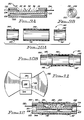
- a perspective, sectional view and end view, respectively, of a sensor body 100 As indicated in Fig. 7A, the sensor body 100 comprises a cylindrical shaped member, a center portion of which has been removed so as to provide a flat portion 102 upon which the sensor circuitry, as described below, may be mounted.
- Circumferential ridges 101, 103 at each end of the body 100 define recessed end portions 105. These ridges advantageously provide a uniform thickness welding surface to which titanium rings 144 and 146 can be welded, as described below.
- a hole 104 passes through one end of the sensor body 100 to the platform area 102; similarly, another hole 106 passes through the other end of the sensor body 100 to the platform area 102.
- a longer hole 108 passes through the entire length of the sensor body 100 under the platform area 102.
- the sensor body is made from titanium. It has a length of approximately 0.3 inches, and a diameter of approximately 0.1 inches.
- the sensor circuitry is mounted on a ceramic substrate 110, as shown in Figs. 8A and 8B.
- Fig. 8A shows a top view of the ceramic substrate and Fig. 8B shows a side view thereof.
- the ceramic substrate 110 has conductive regions (a metallic layer) deposited and etched thereon using conventional techniques. As shown in Fig. 8A, there are three conductive areas or regions (distinguished by a different style of cross-hatching), each electrically insulated from the others, that are placed on the substrate 110.
- a first conductive region connects one end 112 of the substrate with a center area 114 by way of a conductive track 113.
- a second conductive region connects the other end of the substrate 116 to a front edge of the substrate 118.
- a third conductive region connects a first pad area 120 with a second pad area 122 by means of a conductive track 123.
- the anode of LED 32 (see Fig. 2) is bonded to the central pad or conductive area 114 using a conductive polymer, in conventional manner.
- a conductive reflector 150 shown in Figs. 11 and 12 may be first bonded to area 114, with the cathode of LED 32 being bonded to the reflector 150. However, for clarity, this reflector 150 is omitted from Fig. 8A.
- the collector of phototransistor 34 is bonded to pad 120, and the collector of phototransistor 36 is bonded to pad 122.
- This bonding is done using a commercially available bonding methods, such as eutectic bonding techniques.
- a thin film resistor of an appropriate value is deposited or otherwise placed on the ceramic substrate 110 in conventional manner so as to be electrically connected between pad area 114 and the end portion of the substrate 116. In the preferred embodiment, this resistor R1 has a value of approximately 500 ohms.
- a first bonding wire 124 is connected between the emitter of phototransistor 34 and the front edge conductive area 118.
- another bonding wire 126 connects the emitter of phototransistor 36 and the area 118.
- still another bonding wire 128 connects the cathode of LED 32 to the conductive track 123 that connects the pad 120 to the pad 122.
- Conventional hybrid circuit mounting and bonding techniques are used in order to bond the LED and phototransistors to their desired locations on the ceramic substrate 110, and in order to connect the bonding wires 124, 126 and 128 to their desired locations.
- Feedthrough wires 132 and 134 are, in the preferred embodiment, made from 0.005 inch diameter 80/20 platinum-irridium (Pt-Ir) wire. It has been shown in the prior art that the Pt-Ir material is very stable, with a tendency to neither migrate nor oxidize. The contact that the Pt-Ir makes with the printed gold on the circuit is quite reliable. A high Al203 frit is preformed over respective lengths of such wire, and the wire-coated-with-frit is inserted into holes 104 and 106. The sensor body and frit are then fired at a temperature and duration compatible to form a hermetic, biocompatible, stable seal in holes 104 and 106 through which the feedthrough wires 132 and 134 pass.
- Pt-Ir platinum-irridium
- the sensor body 100 After the sensor body 100 has the feedthrough wires 132 and 134 inserted and sealed into holes 104 and 106, it is combined with the hybrid assembly of Fig. 8 to form a sensor body assembly 130 as shown in Figs. 9A and 9B.
- the bottom side of the ceramic substrate 110 is bonded to the platform area 102 of the sensor body.
- the feedthrough wires 132 and 134 are then bent and welded to the end pads 112 and 116, respectively, of the ceramic substrate 110.
- the pins 132 and 134 thus provide a means for making electrical contact with the sensor circuitry located on the substrate 110. It is noted that the pin or feedthrough 132 electrically corresponds to the terminal 38 in Fig. 2, and the pin or feedthrough 134 electrically corresponds to the terminal 40 in Fig. 2.
- FIG. 10A an exploded side sectional view of a sensor lens assembly 140 is shown.
- This assembly includes a glass tube 142 to which two end rings 144 and 146 will be attached.
- Fig. 10B shows the sensor lens assembly 140 in its assembled form.
- the end rings 144 and 146 are slideably inserted into desired locations at each end of the glass tube 142 until ridges 145 (on the outer diameter of end ring 144) and ridge 147 (on the outer diameter of end ring 146) abut up against the end of the glass tube 142.
- Heat is then applied to each end of the glass tube 142 in order to permanently bond the end rings 144 and 146 to the glass tube.
- This heat is applied by inductive heating of the metal rings 144 and 146.
- a temperature of around 700 degrees centigrade for 30-60 seconds is used for this purpose. Applying this amount of heat causes the glass tube to deform slightly as shown at 149 in Fig. 10B.
- the glass tube 142 is soda lime glass. This type of material advantageously chemically reacts with the titanium end rings 144 and 146 when heat is applied as above described in order to form a very tight, chemical bond between the titanium end rings and the glass tube.
- the temperature coefficients of expansion and contraction of the two materials must be matched to within a few parts per million per degree Celcius.
- the wall thicknesses, particularly of the metal rings, must be small (in the case of the metal rings, 0.002 inches).
- the annular clearance between the glass and metal must be uniform and small.
- the temperature to which the glass is heated must exceed the softening point without reaching the melting point. This temperature must be controlled such that there are not more than trivial, tensile residual stresses in the glass upon recovery to normal dimensions near room temperature.
- FIG. 11 there is shown a view of an unformed reflector 150 that is designed to be inserted around and/or under the LED 32 on the ceramic assembly 130.
- the reflector is machined by standard photo chemical etching means.
- the reflector may, in a subsequent operation, be formed into the appropriate shape by a tool and die.
- Large wings of the reflector 150 are folded along lines 152, and the short stubs of the reflector 150 are folded along the lines 154.
- the folded reflector assembly is, in the preferred embodiment, placed under the LED 32 during assembly.
- the reflector is made of a conductive material, such as brass or titanium. Once in place, the reflector will electrically connect the LED 32 to pad 114. Attachment is made with conductive adhesive, such as Ag epoxy or Polyimide.
- the reflector serves two purposes: (1) it increases the light launched into the blood that would otherwise not directly impinge upon the lense; and (2) it reduces the amount of light traveling directly from the LED to the phototransistor without first interacting with the blood.
- FIG. 12 a sectional view of the completed sensor assembly 42 is shown.
- This assembly includes the sensor lens assembly 140 into which the hybrid sensor assembly 130 has been inserted.
- the titanium sensor body 100 is laser welded to the titanium end rings 144 and 146 using conventional laser welding techniques.
- the ends of the sensor body have been designed to simplify the laser welding process and to decrease the rejection ratio of this procedure.
- Flanges 101, 103 provide ends that form uniform, thin surfaces for welding to the metal rings of the lense assembly.
- the annular clearance between the rings and the body is kept to less than a few thousandths of an inch. This requires strict adherence to tolerances on the linearity of the lense assembly.
- the weld flanges offer the following advantages.
- the hybrid sensor assembly 130 is totally sealed within the sensor assembly.
- the tightness or hermeticity of the seal is tested to at least 10 ⁇ 8 cc air/sec at one atmosphere pressure.
- the sensor circuit can readily function as above-described in connection with Figs. 2-6 by applying the appropriate drive signals or voltage measurement signals to the feedthrough pins 132 and 134.
- light emitted by the LED 32 is directed by the reflector 150 up through the soda lime glass sensor wall 142. Any reflections of this light can then similarly pass back through the lens 142 to the phototransistors 34 and 36.
- the sensor as shown in Fig. 12 can thus be incorporated within a desired measurement system and implanted within a patient for the purpose of sensing the reflective properties of a body fluid to which the sensor is exposed.
- the senor utilizes spectrophotometric analysis of the reflectance of light by blood (a body fluid).
- blood a body fluid
- This principle has been described in the art, and it has been shown that reflectance is related to oxygen saturation. That is, oxygen saturation of whole blood can be estimated by analyzing the optical intensity of reflected light.
- MVO2 mixed venous oxygen
- This reflectance value varies to 0% as the MVO2 concentration changes. (It is noted that in Fig. 3, the curve labeled 100% corresponds to the maximum reflectivity possible.) Furthermore, sensor signal amplitude is directly proportional to the intensity of the reflected light.
- the senor 42 is embedded within a pacing lead 60 as shown in Fig. 13A.
- the pacing lead 60 is preferably a bilumen pacing lead having two conductors 68 and 70 passing through most of the length thereof. These conductors may be of conventional type, typically realized with a helically wound conductive wire.
- a cross-sectional view of the bilumen portion of the pacing lead 60 is shown in Fig. 13B
- a bilumen pacing lead is shown in Figs. 13A and 13B
- a coaxial type pacing lead could also be employed for the lead, and conventional break-out techniques could be used to separate the two coaxial conductors so that they could interface with the sensor as shown in Fig. 13A.
- conventional break-out techniques are used towards the proximal end of the lead 60, not shown in Fig. 13A, in order to allow a conventional coaxial bipolar connector to interface with the pacemaker connector 62.
- the feedthrough pin 132 is connected to the conductor 68 using a conventional crimp connector 162.
- the materials selected for the crimp connector 162 and the conductor 68 should not create a galvanic potential that would promote corrosion.
- Pt-Ir and stainless steel provide a strong, non-corrosive bond.
- a stylet tube 164 made from stainless steel hypodermic tubing, coated with a thin polyimide coating over the portion of the tubing that may come in contact with the titanium sensor body 100, is passed through the lower hole 108 of the sensor. (Polyimide is a commercially available insulation material.) The purpose of the polyimide coating is to insulate the stylet tube 164 from the titanium sensor body 100.
- the helically wound conductor 70 is connected to the stylet tube 164 in a conventional manner at both ends of the stylet tube.
- the stylet tube 164 is of the same material as the helically wound conductor 70.
- the feedthrough terminal 134 is bent down to make contact with the stylet tube 164 and is welded or bonded to the stylet tube using conventional laser welding or other bonding techniques. Epoxy fills the space between the protruding portions of the end rings 144 and 146, and further helps to seal the entire assembly.
- a thin layer of polyurethane 166 coats the length of the lead 60 along the length of the lead where the sensor is located. (This thin layer 166 could also coat much of the length of the lead, as is commonly done with many pacing leads.) This coating is in addition to the silicone rubber tubing 168 that forms the outer body of the lead.
- the polyurethane layer 166 is substantially transparent to the light energy emitted by the LED 32 (which light has a wavelength on the order of 660 nm).
- the polyurethane coating presents a transparent medium for light transmission and a benign coating which minimizes tissue growth, thereby keeping the "window" through which the light energy must pass, relatively clean.
- FIG. 14 A schematic representation of the pacemaker lead of Fig. 13A is shown in Fig. 14 wherein a pacer 56 has a two-conductor lead attached thereto.
- a first conductor 180 attaches to the input terminal 132 of the sensor 42.
- a second conductor 190 passes through the sensor and is attached to a tip electrode 170, and to the output terminal 134 of sensor 42.
- the senor 42 could also be incorporated into a bipolar pacing lead. If bipolar pacing is employed, two conductors need to pass by the sensor in order to make electrical contact with the tip and ring electrodes of the bipolar lead, respectively. If a separate additional conductor is used to contact the sensor, the body of the bipolar lead (assuming the sensor 42 is embedded near the distal tip of the lead) must have three conductors therein.
- a tri-lumen lead of the type shown in the sectional view of Fig. 15A and the schematic representation of Fig.
- the titanium sensor body 100 (Fig. 7) has two long holes 108 passing through the lower half thereof.
- FIG. 16A Another possible configuration is a bilumen pacing lead as shown in the sectional view of Fig. 16A and corresponding schematic representation of Fig. 16B.
- Figs. 16A and 16B are similar to Figs. 15A and 15B, respectively, but the lower lumen of Fig. 16A contains coaxial conductors 190 and 192, with conductor 190 being of a smaller diameter helix and inside of the larger helix of conductor 192, each insulated from the other with conventional insulating material 193.
- Fig. 16B it is seen that the innermost conductor 190 of the coaxial conductors goes to the tip electrode 170 and to the sensor output 134.
- the outer conductor 192 goes to the ring electrode 172 of the bipolar lead.
- the titanium sensor body 100 is itself an electrical conductor. As such, the body itself, or a contiguous portion of it, could function as the ring electrode in a bipolar mode. Alternatively, one of the conductive paths through the sensor assembly (to reach a distal tip or ring electrode, or to make contact with the return pin 134 of the sensor 42) could be the titanium body 100. In accordance with this approach, a conductor within the lead is securely attached to the proximal end of the sensor body 100, and a continuation of this conductor is attached to the distal end of the sensor body 100. This approach is schematically illustrated in Fig. 17, wherein a pacemaker 56 has a three-conductor lead attached thereto.
- a first conductor 194 attaches to the input terminal 132 of the sensor 42.
- a second conductor 196 passes through the sensor and is attached to a tip electrode 170, as well as the output terminal 134 of the sensor 42. (The attachment of the terminal 134 could be made internal to the sensor 42, if desired.)
- a third conductor 198 is electrically attached to the proximal end of the titanium body 100.
- the ring electrode 172 is attached to the distal end of the titanium body 100.
- the configuration of Fig. 17 can be used to pace in either a unipolar or bipolar mode of operation.
- unipolar operation no signals or voltage potentials are applied within the pacer 56 to conductors 194 or 198. Rather, a negative pacing pulse is applied to conductor 196, and the positive voltage potential within the pacemaker 56 is applied to the can or case of the pacemaker 56 in conventional manner.
- the distal tip 170 paces unipolarly, cathodically.
- the desired sensor drive signal is applied to conductor 194, and the negative voltage potential within the pacemaker 56 is applied to conductor 196.
- the can of the pacemaker 56 is allowed to float (not connected to any voltage potentials). Thus, current passes only through the sensor, not through the tip electrode 170.
- Fig. 18 there is shown still another embodiment of the present invention used with a bipolar pacing lead configuration in which the pacing lead contains only two conductors 200 and 202.
- a blocking diode 204 is added to the sensor circuit.
- both conductors of the lead are used during sensor operation: conductor 200 for the drive signal connected to the input terminal 132 of sensor 42 and conductor 202 for the return path connected to the output terminal 134 of sensor 42.
- both conductors are used during conventional bipolar pacing/sensing: conductor 200 being connected to the tip electrode 170 through diode 204 and conductor 202 being connected to the ring electrode 172.
- the sensor drive signal is applied to conductor 200, and the negative voltage is applied to conductor 202, which back biases the diode such that current passes only through the sensor, not through the tip electrode 170.
- both conductors within the lead are used for two functions.
- This embodiment assumes that the sensor 42 is not operational at a time when the tip/ring electrodes of the pacing lead are operating. Fortunately, as has been explained previously in connection with Figs. 5-6, a pacemaker is not operative during a refractory time period, and the sensor 42 could thus operate during this refractory time period.
- the configuration of Fig. 18 can be used advantageously to pace in either a unipolar or a bipolar mode of operation.
- Unipolar pacing is achieved by floating conductor 202, applying a negative pacing pulse to conductor 200, and connecting the positive voltage potential of the pacemaker to the case or can of the pacemaker 56.
- Bipolar pacing is achieved by applying a negative pacing pulse to conductor 200, floating the pacemaker case, and connecting the positive voltage potential to conductor 202.
- Sensor operation is achieved by connecting the sensor drive signal to conductor 200, connecting the negative voltage potential of the pacemaker 56 to conductor 202, and floating the pacemaker case.
- the blocking diode 204 could be eliminated, thereby simplifying the number of components involved. However, if diode 204 is removed, the sensing drive signal could potentially stimulate the heart. This should not happen, however, if the sensing drive signal is synchronized with the heart's refractory period, as it would be as described above. This is because the heart is not capable of being stimulated while it is refractory.
- Fig. 19 provides a sensor process development tree of the assembly procedure. The main processes are described below.
- the Fused Ring-Tube Assembly 205 includes fusing the glass tube and the two titanium end seal rings, wherein the seal produced must be hermetic, fitting well over the titanium sensor body and removing any oxides therefrom. Platinum-irridium feedthroughs and the titanium sensor body are fired to produce Titanium Bodies with Feedthroughs 206 wherein said feedthroughs must be hermetic, insulated, and able to withstand laser weld.
- the Complete Hybrid Assembly 207 comprises the hybrid substrate, one LED, two phototransistors, one resistor, and the reflector. The assembled hybrid must pass conventional hybrid lab quality control (Q.C.) requirements, laser weld, long-term aging, and shock under load.
- the Hybrid-Body Assembly 208 is formed by bonding the hybrid substrate to the titanium sensor body and welding the feedthroughs to the hybrid substrate. The mounted Hybrid-Body Assembly 208 must then pass laser weld, thermal aging, and shock. To provide a hermetic seal over the sensor, the Hybrid-Body Assembly 208 is slideably mounted into the Fused Ring-Tube Assembly 205 and laser welded to produce the Hermetic Sensor 209 such that the titanium-glass tube forms a hermetic seal with the titanium body with only minimal residual stress on the glass and no effect on the hybrid. Finally the proximal platinum-irridium feedthrough is crimped to proximal portion of the conductor. The other feedthrough is welded to the stylet tube on the distal side. Epoxy is potted between the protruding protions of the end rings. The resultant Sensor-Tube Assembly 210 must provide a reliable connection to the lead coils and insulation and pass a high potential (Hypot) dielectric test.
- the LED 32 of the sensor 42 in the preferred embodiment, is a commercially available LED chip, type URDA-35E, commercially available from Shin-Itzu.
- the phototransistors 34 and 36 are likewise commercially available components, type F5OB, available from Siemens. Equivalent devices are available from numerous other manufacturers. As has been indicated, oxygen staturation of the blood is estimated by analyzing the optical intensity of reflected light at a specific wavelength (660 nm).
- a hermetically sealed sensor that can advantageously be embedded within a pacing lead adapted for implantation within a human body.
- the sensor can be activated during a time when the pacing lead is not being used by the pacemaker.
- These sensed reflective properties provide an indication of the oxygen content of the blood.
- This information is then processed and used by a rate-responsive pacemaker in order to adjust the pacing interval of the pacemaker in an appropriate manner.
Landscapes
- Health & Medical Sciences (AREA)
- Life Sciences & Earth Sciences (AREA)
- Physics & Mathematics (AREA)
- Cardiology (AREA)
- Heart & Thoracic Surgery (AREA)
- Veterinary Medicine (AREA)
- Biophysics (AREA)
- Public Health (AREA)
- Engineering & Computer Science (AREA)
- Biomedical Technology (AREA)
- General Health & Medical Sciences (AREA)
- Animal Behavior & Ethology (AREA)
- Surgery (AREA)
- General Chemical & Material Sciences (AREA)
- Medical Informatics (AREA)
- Pathology (AREA)
- Optics & Photonics (AREA)
- Chemical & Material Sciences (AREA)
- Chemical Kinetics & Catalysis (AREA)
- Molecular Biology (AREA)
- Spectroscopy & Molecular Physics (AREA)
- Hematology (AREA)
- Physiology (AREA)
- Nuclear Medicine, Radiotherapy & Molecular Imaging (AREA)
- Radiology & Medical Imaging (AREA)
- Electrotherapy Devices (AREA)
- Measurement Of The Respiration, Hearing Ability, Form, And Blood Characteristics Of Living Organisms (AREA)
Claims (23)
- Capteur (42) médical implantable, fermé de manière étanche, utilisé de préférence en association avec un système (56) de stimulation implantable fonctionnant en réponse à une fréquence afin de détecter un paramètre souhaité associé au tissu corporel, y compris les fluides corporels, dans lequel le capteur (42) médical est implanté, ce capteur (42) comprenant :
un tube creux ayant une fenêtre (142) fermée de manière étanche en son sein ;
un substrat (110) inséré dans le tube ;
des moyens (32) formant diodes émettrices de lumière disposées sur le substrat (110) afin d'émettre de la lumière dont la fréquence est comprise dans une gamme prescrite en réponse à un signal d'attaque, ces moyens (32) formant diodes émettrices de lumière étant placées sur le substrat (110) de façon à permettre qu'au moins une partie de la lumière passe par la fenêtre (142), vienne en contact avec le tissu corporel à l'extérieur de la fenêtre (142), et soit réfléchie dans la fenêtre ;
des moyens (34, 36) à phototransistors placés sur le substrat (110) afin de recevoir de la lumière ayant une fréquence comprise dans une gamme prescrite et qui est reçue par la fenêtre (142), et de produire un signal de sortie ayant des caractéristiques qui varient en fonction d'au moins un paramètre de la lumière reçue par la fenêtre (142);
des moyens (113, 114, 118, 120, 122, 123) de connexion destinés à connecter les moyens (32) formant diodes émettrices de lumière et les moyens (34, 36) à phototransistors selon une configuration de circuit souhaitée, et destinés à connecter une première borne (112) aux moyens (32) formant diodes émettrices de lumière et destinés à connecter une seconde borne (116) aux moyens (34, 36) à phototransistors ;
des moyens (145, 147, 101, 103) d'étanchéité fixés de manière étanche à chaque extrémité du tube afin de rendre étanche le substrat (110), les moyens (32) formant diodes émettrices de lumière, les moyens (34, 36) phototransistor et les moyens (113, 114, 118, 120, 122, 123) de connexion à l'intérieur du tube, ces moyens d'étanchéité (145, 147, 101, 103) comportant des moyens (132, 134) de traversée destinés à réaliser un contact électrique entre un point extérieur du tube et les première et seconde (112, 116) bornes ;
des moyens (46) destinés à produire le signal d'attaque et à l'appliquer aux moyens (32) formant diodes émettrices de lumière par l'intermédiaire des première et seconde (112, 116) bornes, ces moyens (46) de production du signal d'attaque comportant des moyens (72, 74, 78, 80) destinés à produire un courant d'attaque monophasé en forme d'échelons qui excite les moyens (32) formant diodes émettrices de lumière avec un premier niveau de courant pendant une première durée prescrite, et qui excite les moyens (32) formant diodes émettrices de lumière avec un second niveau de courant pendant une seconde durée qui suit immédiatement la première durée ; et
des moyens (48) pour contrôler le signal de sortie des première et seconde (112, 116) bornes produit par les moyens (34, 36) à phototransistor et pour traiter ce signal afin de procurer un signal de détection qui représente une indication dudit au moins un paramètre de la lumière reçue par la fenêtre (142), ce signal de détection procurant ainsi une mesure d'une caractéristique souhaitée du tissu corporel tel que mesuré par la manière dont ledit au moins un paramètre de lumière est affecté par le fait de venir en contact avec le tissu corporel. - Capteur médical selon la revendication 1, dans lequel les moyens (48) de contrôle et de traitement du signal de sortie produit par les moyens (34, 36) à phototransistor comprennent des moyens (90, 92, 94, 96) destinés à déterminer la variation du signal de sortie sous l'effet d'une variation de la quantité de lumière réfléchie dans la fenêtre (142) entre la première durée et la seconde durée.
- Capteur médical selon la revendication 1 ou 2, dans lequel les moyens (32) formant diodes émettrices de lumière émettent de la lumière à une fréquence qui varie en fonction de la teneur en oxygène du sang.
- Capteur médical selon l'une quelconque des revendications 1 à 3, dans lequel le tube creux est en un matériau qui est sensiblement transparent à la lumière émise par les moyens (32) formant diodes émettrices de lumière et à la lumière reçue par les moyens (34-36) à phototransistor, ce matériau transparent à la lumière comportant la fenêtre (142) fermée de manière étanche par laquelle la lumière passe.
- Capteur médical selon la revendication 4, dans lequel le matériau du tube creux comprend du verre à base de soude et de chaux.
- Capteur médical selon l'une quelconque des revendications 1 à 5, dans lequel les moyens (101, 103, 145, 147) d'étanchéité comportent un anneau (144, 146) métallique qui est inséré dans chaque extrémité du tube creux, les moyens (132, 134) de traversée passant de manière étanche dans ces anneaux (144, 146) métalliques, ces anneaux (144, 146) métalliques étant fixés de manière étanche au tube creux sur les bords du tube de manière à former un joint étanche, correspondant à au moins 10⁻⁸ cm³ d'air par seconde à la pression atmosphérique (1,013 10⁵ Pa)
- Capteur médical selon la revendication 6 dans lequel les anneaux (144, 146) métalliques sont en titane, et dans lequel la fixation étanche entre les anneaux (144, 146) métalliques et les bords du tube creux en verre à base de soude et de chaux est une liaison chimique formée entre le titane et le verre à base de soude et de chaux.
- Capteur médical selon l'une quelconque des revendications 1 à 7, dans lequel les moyens (32) formant diodes émettrices de lumière comprennent une puce (32) formant diode émettrice de lumière fixée au substrat (110) sensiblement en son centre, et comportant en outre une enveloppe (150) réfléchissante placée entre la puce (32) formant diode émettrice de lumière et une partie de la fenêtre (142) du tube creux, de sorte que la lumière émise par la puce (32) formant diode émettrice de lumière est dirigée sensiblement vers le haut en sortant par la fenêtre (142).
- Capteur médical selon l'une quelconque des revendications 1 à 8 dans lequel les moyens (34, 36) à phototransistor comprennent au moins deux puces (34, 36) à phototransistor qui sont fixées au substrat (110), une puce (34) à phototransistor étant placée d'un côté des moyens (32) formant diodes émettrices de lumière mais encore sous une partie de la fenêtre (142) ; et l'autre puce (36) à phototransistor étant placée de l'autre côté des moyens (32) formant diodes émettrices de lumière, mais cependant encore sous une autre partie de la fenêtre (142), les dites au moins deux puces (34, 36) à phototransistor étant connectées électriquement en parallèle au moyen de moyens (120, 122, 123, 118, 124, 126) de connexion.
- Capteur médical selon l'une quelconque des revendications 1 à 9, dans lequel le capteur est d'une pièce avec une ligne (60) de stimulation implanté ayant un connecteur (62) à l'une ses extrémités et des moyens (66) formant électrodes à son autre extrémité, les moyens (66) formant électrodes comprenant des moyens (170) pour venir en contact électrique avec le tissu corporel lorsque la ligne (60) est implantée dans un corps, et le connecteur comprend des moyens destinés à mettre en interface, à la fois électriquement et physiquement, la ligne (60) avec le système (56) de stimulation ; un premier conducteur (70, 182, 190) isolé ayant une extrémité distale couplée au moyen (66) formant électrode et une extrémité proximale couplée au connecteur (62) et des moyens (66, 180, 194, 200) destinés à transmettre le signal d'attaque et le signal de sortie entre les moyens (42) formant capteur et le connecteur (62).
- Capteur médical selon la revendication 10 comprenant en outre une diode (204) et un second conducteur (202) ; dans lequel l'extrémité proximale du premier conducteur 200 est couplée à l'extrémité distale du premier conducteur (200) par l'intermédiaire de la diode (204) ; l'extrémité proximale est également connectée électriquement au moyen (200) afin de transmettre le signal d'attaque au capteur ; le second conducteur (202) est électriquement connecté à une électrode (172) à anneaux située à proximité d'une extrémité distale du second conducteur (202) ainsi qu'aux moyens de traversée du boîtier.
- Capteur médical selon la revendication 10 dans lequel les moyens destinés à transmettre le signal d'attaque aux capteurs comprennent un deuxième conducteur couplé à une extrémité proximale du connecteur et couplé à une extrémité distale des moyens de traversée du boîtier.
- Capteur médical selon la revendication 12 dans lequel les moyens (132, 134) de traversée du boîtier sont en outre couplés au premier conducteur.
- Capteur médical selon la revendication 12 ou 13, dans lequel la ligne (60) comporte en outre un troisième conducteur (192), électriquement isolé des premier et deuxième conducteurs (180, 182), ce troisième conducteur (192) étant connecté électriquement à une électrode (172) en anneau située à proximité d'une extrémité distale de la ligne (60).
- Capteur médical selon la revendication 14, dans lequel le troisième conducteur passe par une partie du capteur sans venir en contact électrique avec celui-ci.
- Capteur médical selon la revendication 14, dans lequel le troisième conducteur (198) vient en contact électrique avec le capteur.
- Capteur médical selon la revendication 14 dans lequel les premier et troisième conducteurs (190, 192) sont coaxiaux à l'intérieur de la ligne.
- Capteur médical selon la revendication 12, dans lequel la ligne (60) comporte une ligne bipolaire ayant une électrode (172) en anneau et une électrode (170) en pointe, et dans lequel les moyens de traversée du boîtier comportent des première et seconde bornes (132, 134) de traversée, et dans lequel en outre l'un des deux premier et deuxième conducteurs (180,190) est connecté électriquement à la première borne (132) de traversée, et l'autre (190) des premier et deuxième conducteurs est connecté électriquement à la seconde borne (134) de traversée.
- Capteur médical selon la revendication 18 dans lequel les premier et deuxième conducteurs sont coaxiaux à l'intérieur de la ligne.
- Capteur médical selon la revendication 12 dans lequel la ligne (60) comporte en outre un troisième conducteur, isolé électriquement des premier et deuxième conducteurs, le troisième conducteur étant connecté à l'extrémité proximale du boîtier, et dans lequel le corps du boitier est également utilisé en tant qu'électrode en anneau.
- Procédé d'utilisation d'un capteur médical qui comporte des moyens formant diodes émettrices de lumière destinés à émettre une impulsion lumineuse qui est dirigée vers un type souhaité de matériau organique à analyser, cette impulsion lumineuse étant ensuite reçue par des moyens à phototransistor, une propriété souhaitée du matériau organique pouvant être déterminée par la manière dont au moins une propriété détectable de l'impulsion lumineuse est affectée par le matériau organique ; ce procédé comprenant les étapes qui consistent à :a) exciter les moyens formant diodes émettrices de lumière par un premier courant d'attaque en forme d'échelon pendant une première durée ;b) exciter les moyens formant diodes émettrices de lumière par un second courant d'attaque en forme d'échelon de même polarité que le premier courant d'attaque pendant une seconde durée suivant immédiatement la première durée ;c) contrôler les impulsions lumineuses reçues par les moyens à phototransistor pendant les première et seconde durée pour déterminer le changement des impulsions lumineuses à la suite du fait qu'elles sont venues en contact avec le matériau organique ; etd) traiter la variation mise en évidence à l'étape (c) pour déterminer une propriété souhaitée du matériau organique.
- Procédé selon la revendication 21, dans lequel le deuxième courant d'attaque utilisé à l'étape (b) pour exciter les moyens formant diodes émettrices de lumière est inférieur au premier courant d'attaque utilisé à l'étape (a).
- Procédé selon la revendication 21 ou 22 dans lequel le matériau organique analysé par le capteur médical comprend du sang et dans lequel en outre la propriété détectable contrôlée par le capteur médical est la quantité de l'impulsion lumineuse qui est réfléchie par le sang, cette quantité de lumière réfléchie pouvant être mise en relation avec la quantité d'oxygène dans le sang au moyen du traitement de l'étape (d).
Applications Claiming Priority (2)
| Application Number | Priority Date | Filing Date | Title |
|---|---|---|---|
| US10706287A | 1987-10-08 | 1987-10-08 | |
| US107062 | 1987-10-08 |
Publications (3)
| Publication Number | Publication Date |
|---|---|
| EP0314937A2 EP0314937A2 (fr) | 1989-05-10 |
| EP0314937A3 EP0314937A3 (en) | 1990-05-23 |
| EP0314937B1 true EP0314937B1 (fr) | 1995-12-13 |
Family
ID=22314648
Family Applications (1)
| Application Number | Title | Priority Date | Filing Date |
|---|---|---|---|
| EP19880116645 Expired - Lifetime EP0314937B1 (fr) | 1987-10-08 | 1988-10-07 | Capteur implantable du taux d'oxygène dans le sang et procédé d'emploi |
Country Status (4)
| Country | Link |
|---|---|
| EP (1) | EP0314937B1 (fr) |
| JP (1) | JPH01212539A (fr) |
| AU (1) | AU604567B2 (fr) |
| DE (1) | DE3854781T2 (fr) |
Cited By (7)
| Publication number | Priority date | Publication date | Assignee | Title |
|---|---|---|---|---|
| US6096065A (en) | 1997-09-29 | 2000-08-01 | Boston Scientific Corporation | Sheath for tissue spectroscopy |
| US6289229B1 (en) | 1998-01-20 | 2001-09-11 | Scimed Life Systems, Inc. | Readable probe array for in vivo use |
| US6364831B1 (en) | 1997-09-29 | 2002-04-02 | Boston Scientific Corporation | Endofluorescence imaging module for an endoscope |
| US6731976B2 (en) | 1997-09-03 | 2004-05-04 | Medtronic, Inc. | Device and method to measure and communicate body parameters |
| US6882875B1 (en) | 1997-09-29 | 2005-04-19 | Boston Scientific Corporation | Visible display for an interventional device |
| US7729773B2 (en) | 2005-10-19 | 2010-06-01 | Advanced Neuromodualation Systems, Inc. | Neural stimulation and optical monitoring systems and methods |
| US8126531B2 (en) | 1996-11-21 | 2012-02-28 | Boston Scientific Scimed, Inc. | Miniature spectrometer |
Families Citing this family (17)
| Publication number | Priority date | Publication date | Assignee | Title |
|---|---|---|---|---|
| US5024226A (en) * | 1989-08-17 | 1991-06-18 | Critikon, Inc. | Epidural oxygen sensor |
| US5076271A (en) * | 1990-07-19 | 1991-12-31 | Siemens-Pacesetter, Inc. | Rate-responsive pacing method and system employing minimum blood oxygen saturation as a control parameter and as a physical activity indicator |
| US5113862A (en) * | 1990-09-25 | 1992-05-19 | Siemens Pacesetter, Inc. | Blood oxygen sensor having leakage compensation |
| DE4141113A1 (de) * | 1991-12-13 | 1993-06-17 | Hornschuch Ag K | Grossflaechige verkleidungsteile aus thermoplastischen kunststoffen fuer dfen kfz-innenbereich und verfahren zu deren herstellung |
| US6324418B1 (en) | 1997-09-29 | 2001-11-27 | Boston Scientific Corporation | Portable tissue spectroscopy apparatus and method |
| US6238348B1 (en) | 1997-07-22 | 2001-05-29 | Scimed Life Systems, Inc. | Miniature spectrometer system and method |
| US6134459A (en) * | 1998-10-30 | 2000-10-17 | Medtronic, Inc. | Light focusing apparatus for medical electrical lead oxygen sensor |
| US6198952B1 (en) | 1998-10-30 | 2001-03-06 | Medtronic, Inc. | Multiple lens oxygen sensor for medical electrical lead |
| US6125291A (en) * | 1998-10-30 | 2000-09-26 | Medtronic, Inc. | Light barrier for medical electrical lead oxygen sensor |
| US6125290A (en) * | 1998-10-30 | 2000-09-26 | Medtronic, Inc. | Tissue overgrowth detector for implantable medical device |
| US6444970B1 (en) | 1998-06-26 | 2002-09-03 | Scimed Life Systems, Inc. | Miniature low-noise photodiode system |
| EP1827583B1 (fr) * | 2004-12-22 | 2013-01-23 | Proteus Digital Health, Inc. | Structures hermetiquement scellees implantables |
| JP4617204B2 (ja) * | 2005-05-31 | 2011-01-19 | 株式会社ムトウ | 光通信システム |
| EP2282668A1 (fr) | 2008-03-25 | 2011-02-16 | Medtronic, Inc. | Conducteurs cardiaques robustes de forte et de faible puissance à détecteurs intégrés |
| US8903660B2 (en) * | 2010-06-24 | 2014-12-02 | The Invention Science Fund I, Llc | Rejuvenation or preservation of germ cells |
| WO2012070286A1 (fr) * | 2010-11-24 | 2012-05-31 | アルプス電気株式会社 | Unité de lentille |
| CN115633964B (zh) * | 2022-12-08 | 2023-03-03 | 北京品驰医疗设备有限公司 | 电极触点、皮层电极及植入式医疗器械 |
Family Cites Families (4)
| Publication number | Priority date | Publication date | Assignee | Title |
|---|---|---|---|---|
| US4232679A (en) * | 1977-01-26 | 1980-11-11 | Pacesetter Systems, Inc. | Programmable human tissue stimulator |
| DE2717659C2 (de) * | 1977-04-21 | 1985-11-14 | Wirtzfeld, Alexander, Prof. Dr.med., 8195 Egling | Herzschrittmacher |
| DE3107128C2 (de) * | 1981-02-26 | 1984-07-05 | Heinze, Roland, Dipl.-Ing., 8000 München | Regelschaltung zur Anpassung der Stimulationsfrequenz eines Herzschrittmachers an die Belastung eines Patienten |
| EP0257954B1 (fr) * | 1986-08-15 | 1993-06-16 | Medtronic, Inc. | Stimulateur cardiaque avec capteur d'oxygène |
-
1988
- 1988-10-07 EP EP19880116645 patent/EP0314937B1/fr not_active Expired - Lifetime
- 1988-10-07 DE DE19883854781 patent/DE3854781T2/de not_active Expired - Fee Related
- 1988-10-07 AU AU23552/88A patent/AU604567B2/en not_active Ceased
- 1988-10-07 JP JP63253615A patent/JPH01212539A/ja active Pending
Cited By (10)
| Publication number | Priority date | Publication date | Assignee | Title |
|---|---|---|---|---|
| US8126531B2 (en) | 1996-11-21 | 2012-02-28 | Boston Scientific Scimed, Inc. | Miniature spectrometer |
| US8660637B2 (en) | 1996-11-21 | 2014-02-25 | Boston Scientific Scimed, Inc. | Miniature spectrometer |
| US6731976B2 (en) | 1997-09-03 | 2004-05-04 | Medtronic, Inc. | Device and method to measure and communicate body parameters |
| US6096065A (en) | 1997-09-29 | 2000-08-01 | Boston Scientific Corporation | Sheath for tissue spectroscopy |
| US6364831B1 (en) | 1997-09-29 | 2002-04-02 | Boston Scientific Corporation | Endofluorescence imaging module for an endoscope |
| US6383209B1 (en) | 1997-09-29 | 2002-05-07 | Boston Scientific Corporation | Sheath for tissue spectroscopy |
| US6882875B1 (en) | 1997-09-29 | 2005-04-19 | Boston Scientific Corporation | Visible display for an interventional device |
| US6289229B1 (en) | 1998-01-20 | 2001-09-11 | Scimed Life Systems, Inc. | Readable probe array for in vivo use |
| US7302289B2 (en) | 1998-01-20 | 2007-11-27 | Scimed Life Systems, Inc. | Readable probe array for in-vivo use |
| US7729773B2 (en) | 2005-10-19 | 2010-06-01 | Advanced Neuromodualation Systems, Inc. | Neural stimulation and optical monitoring systems and methods |
Also Published As
| Publication number | Publication date |
|---|---|
| EP0314937A2 (fr) | 1989-05-10 |
| JPH01212539A (ja) | 1989-08-25 |
| DE3854781D1 (de) | 1996-01-25 |
| DE3854781T2 (de) | 1996-05-02 |
| AU604567B2 (en) | 1990-12-20 |
| EP0314937A3 (en) | 1990-05-23 |
| AU2355288A (en) | 1989-04-13 |
Similar Documents
| Publication | Publication Date | Title |
|---|---|---|
| US4815469A (en) | Implantable blood oxygen sensor and method of use | |
| EP0314937B1 (fr) | Capteur implantable du taux d'oxygène dans le sang et procédé d'emploi | |
| US5438987A (en) | Implantable lead for sensing a physiologic parameter of the body | |
| US5275171A (en) | Implantable lead and sensor | |
| US4730389A (en) | Method for fabrication of an implantable hermetic transparent container | |
| EP1124609B1 (fr) | Detecteur d'oxygene a plusieurs lentilles pour derivation electrique medicale | |
| US5564434A (en) | Implantable capacitive absolute pressure and temperature sensor | |
| CA1319176C (fr) | Stimulateur cardiaque oxymetrique | |
| US6125291A (en) | Light barrier for medical electrical lead oxygen sensor | |
| US6134459A (en) | Light focusing apparatus for medical electrical lead oxygen sensor | |
| EP1468641B1 (fr) | Système de surveillance du taux d'oxygène | |
| US5535752A (en) | Implantable capacitive absolute pressure and temperature monitor system | |
| US5358514A (en) | Implantable microdevice with self-attaching electrodes | |
| US5833603A (en) | Implantable biosensing transponder | |
| EP1408863B1 (fr) | Passage hermetique pour dispositif implantable | |
| US7447533B1 (en) | Implantable electronic medical device having an encapsulated optical transducer | |
| EP1124481A1 (fr) | Ensemble de plusieurs capteurs pour conducteur electrique medical | |
| EP0047986A2 (fr) | Transducteur de pression étanche, à circuits intégrés, pour implantation | |
| EP0257954B1 (fr) | Stimulateur cardiaque avec capteur d'oxygène |
Legal Events
| Date | Code | Title | Description |
|---|---|---|---|
| PUAI | Public reference made under article 153(3) epc to a published international application that has entered the european phase |
Free format text: ORIGINAL CODE: 0009012 |
|
| AK | Designated contracting states |
Kind code of ref document: A2 Designated state(s): DE FR GB IT NL SE |
|
| PUAL | Search report despatched |
Free format text: ORIGINAL CODE: 0009013 |
|
| AK | Designated contracting states |
Kind code of ref document: A3 Designated state(s): DE FR GB IT NL SE |
|
| 17P | Request for examination filed |
Effective date: 19900710 |
|
| 17Q | First examination report despatched |
Effective date: 19921106 |
|
| RAP1 | Party data changed (applicant data changed or rights of an application transferred) |
Owner name: PACESETTER AB |
|
| GRAA | (expected) grant |
Free format text: ORIGINAL CODE: 0009210 |
|
| AK | Designated contracting states |
Kind code of ref document: B1 Designated state(s): DE FR GB IT NL SE |
|
| REF | Corresponds to: |
Ref document number: 3854781 Country of ref document: DE Date of ref document: 19960125 |
|
| ET | Fr: translation filed | ||
| ITF | It: translation for a ep patent filed | ||
| PG25 | Lapsed in a contracting state [announced via postgrant information from national office to epo] |
Ref country code: SE Effective date: 19960313 |
|
| REG | Reference to a national code |
Ref country code: GB Ref legal event code: 732E |
|
| NLS | Nl: assignments of ep-patents |
Owner name: PACESETTER, INC. |
|
| REG | Reference to a national code |
Ref country code: FR Ref legal event code: TP |
|
| PLBE | No opposition filed within time limit |
Free format text: ORIGINAL CODE: 0009261 |
|
| STAA | Information on the status of an ep patent application or granted ep patent |
Free format text: STATUS: NO OPPOSITION FILED WITHIN TIME LIMIT |
|
| 26N | No opposition filed | ||
| PGFP | Annual fee paid to national office [announced via postgrant information from national office to epo] |
Ref country code: GB Payment date: 19970929 Year of fee payment: 10 |
|
| PG25 | Lapsed in a contracting state [announced via postgrant information from national office to epo] |
Ref country code: GB Free format text: LAPSE BECAUSE OF NON-PAYMENT OF DUE FEES Effective date: 19981007 |
|
| GBPC | Gb: european patent ceased through non-payment of renewal fee |
Effective date: 19981007 |
|
| PGFP | Annual fee paid to national office [announced via postgrant information from national office to epo] |
Ref country code: NL Payment date: 20010925 Year of fee payment: 14 |
|
| PG25 | Lapsed in a contracting state [announced via postgrant information from national office to epo] |
Ref country code: NL Free format text: LAPSE BECAUSE OF NON-PAYMENT OF DUE FEES Effective date: 20030501 |
|
| NLV4 | Nl: lapsed or anulled due to non-payment of the annual fee |
Effective date: 20030501 |
|
| PGFP | Annual fee paid to national office [announced via postgrant information from national office to epo] |
Ref country code: FR Payment date: 20031020 Year of fee payment: 16 |
|
| PGFP | Annual fee paid to national office [announced via postgrant information from national office to epo] |
Ref country code: DE Payment date: 20041130 Year of fee payment: 17 |
|
| PG25 | Lapsed in a contracting state [announced via postgrant information from national office to epo] |
Ref country code: FR Free format text: LAPSE BECAUSE OF NON-PAYMENT OF DUE FEES Effective date: 20050630 |
|
| REG | Reference to a national code |
Ref country code: FR Ref legal event code: ST |
|
| PG25 | Lapsed in a contracting state [announced via postgrant information from national office to epo] |
Ref country code: IT Free format text: LAPSE BECAUSE OF NON-PAYMENT OF DUE FEES;WARNING: LAPSES OF ITALIAN PATENTS WITH EFFECTIVE DATE BEFORE 2007 MAY HAVE OCCURRED AT ANY TIME BEFORE 2007. THE CORRECT EFFECTIVE DATE MAY BE DIFFERENT FROM THE ONE RECORDED. Effective date: 20051007 |
|
| PG25 | Lapsed in a contracting state [announced via postgrant information from national office to epo] |
Ref country code: DE Free format text: LAPSE BECAUSE OF NON-PAYMENT OF DUE FEES Effective date: 20060503 |