EP0314969A2 - Bloc pour des distributeurs à air-huile progressifs en série - Google Patents
Bloc pour des distributeurs à air-huile progressifs en série Download PDFInfo
- Publication number
- EP0314969A2 EP0314969A2 EP88117228A EP88117228A EP0314969A2 EP 0314969 A2 EP0314969 A2 EP 0314969A2 EP 88117228 A EP88117228 A EP 88117228A EP 88117228 A EP88117228 A EP 88117228A EP 0314969 A2 EP0314969 A2 EP 0314969A2
- Authority
- EP
- European Patent Office
- Prior art keywords
- aperture
- lubricant
- assembly
- passageway
- support
- Prior art date
- Legal status (The legal status is an assumption and is not a legal conclusion. Google has not performed a legal analysis and makes no representation as to the accuracy of the status listed.)
- Withdrawn
Links
Images


Classifications
-
- F—MECHANICAL ENGINEERING; LIGHTING; HEATING; WEAPONS; BLASTING
- F16—ENGINEERING ELEMENTS AND UNITS; GENERAL MEASURES FOR PRODUCING AND MAINTAINING EFFECTIVE FUNCTIONING OF MACHINES OR INSTALLATIONS; THERMAL INSULATION IN GENERAL
- F16N—LUBRICATING
- F16N25/00—Distributing equipment with or without proportioning devices
- F16N25/02—Distributing equipment with or without proportioning devices with reciprocating distributing slide valve
-
- F—MECHANICAL ENGINEERING; LIGHTING; HEATING; WEAPONS; BLASTING
- F16—ENGINEERING ELEMENTS AND UNITS; GENERAL MEASURES FOR PRODUCING AND MAINTAINING EFFECTIVE FUNCTIONING OF MACHINES OR INSTALLATIONS; THERMAL INSULATION IN GENERAL
- F16N—LUBRICATING
- F16N7/00—Arrangements for supplying oil or unspecified lubricant from a stationary reservoir or the equivalent in or on the machine or member to be lubricated
- F16N7/30—Arrangements for supplying oil or unspecified lubricant from a stationary reservoir or the equivalent in or on the machine or member to be lubricated the oil being fed or carried along by another fluid
- F16N7/32—Mist lubrication
Definitions
- the subject invention relates to a progressive lubricant feeder, and particularly, to a series progressive feeder for mixing lubricant with air.
- Series progressive lubricant feeder blocks have existed for several decades. These feeder or metering blocks distribute a predetermined amount of lubricant to an object.
- a progressive lubrificant feeder is disclosed in U.S.-A- 3,467,222, issued September 15, 1969, in the name of Gruber.
- This patent discloses a series of individually connected base elements. Each individual base element includes a spool valve disposed within the base element. An end block is connected serially to one end of the base elements and includes an aperture to allow the lubricant to enter the feeder block assembly. Apertures in each end of the base allow the lubricant to exit on each side.
- the first spool valve is shifted to one side to exhaust a metered amount of lubricant from the first base element.
- the second spool valve in the second base element shifts to the same side to distribute or exhaust a second metered amount of lubricant from the second base element. This cycle is repeated for a plurality of individual base elements connected together.
- a mixing valve is used to mix the air with the lubricant downstream of the lubricant feeder assembly.
- a conventional mixing valve has an internal T-shaped configuration to allow the air and lubricant to be mixed therein.
- a first conduit is connected to the feeder block assembly and a second conduit is connected to an air supply source.
- a third conduit interconnects the mixing valve and a spray nozzle for spraying the air/lubricant mixture on the object.
- the invention as claimed is intended to remedy these drawbacks and the advantages offered are mainly that air and lubricant are mixed internally within the lubricant feeder assembly. This eliminates the need for mixing valves and conduits associated therewith for mixing air and lubricant. In addition, an operator will be able to detect a blockage and determine that it occurred in the feeder block assembly.
- the lubricant feeder block assembly for feeding lubricant to an object is of the type including support means comprising at least one support block of generally rectangular configuration and having a pair of end faces and a plurality of side faces therebetween: first aperture means and first passageway means in said support means for allowing lubricant to enter said support means; second aperture means and second passageway means on said support means for allowing lubricant to exit said support means; valve means for distributing lubricant between said first aperture means and said second aperture means, said valve means being interposed between said first and second passageway and is essentially characterized in that it further comprises third aperture means and third passageway means in said support means for allowing air to enter and be mixed with the lubricant within said support means before exiting said second aperture means.
- a progressive series or lubricant feeder block assembly for feeding lubricant such as oil to an object (not shown) is generally shown at 10 in Figure 1.
- the assembly 10 allows a predetermined amount of lubricant to be discharged in a serial manner to an object as conventionally known in the art.
- the assembly 10 includes support means, generally indicated at 12, forming at least one support block 14.
- the support means 12 comprises a plurality of support blocks 14 being generally rectangular in configuration and having a pair of end faces 16 and a plurality of side faces 18 therebetween.
- the support means typically includes an inlet support block 14, intermediate support blocks 14′ and an end block 14 ⁇ serially connected together.
- the support blocks 14, 14′, 14 ⁇ are connected together by fasteners (not shown).
- the assembly 10 includes a first aperture means 20 forming at least one first aperture 20 in the support means 12 for allowing lubricant to enter the support means 12.
- the first aperture means 20 comprises a first aperture 20 in the side face 18 of the inlet support block 14.
- the first aperture 20 is threaded to allow a fitting and corresponding conduit (not shown) to be threadably engageable with the first aperture 20.
- the assembly 10 also includes second aperture means 22 forming at least one, and preferably a plurality of, second apertures 22 in the support means 12 for allowing lubricant to exit the support means 12.
- the second aperture means 22 comprises a second aperture 22 in each of the end faces 16 of the support blocks 14, 14′, 14 ⁇ .
- one second aperture 22 is on each side of the first aperture 20.
- the assembly 10 further includes first passageway means 24 forming at least one, and preferably a plurality of, passageways 24 within the support means 12 to allow lubricant to flow from the first aperture 20 to the second apertures 22.
- the first passageway means 24 comprises a series of first passageways 24 within the support blocks 14, as illustrated in Figures 2 through 4.
- the first passageways 24 communicate with each other from one support block 14 to an adjacent support block 14.
- the first passageways 24 interconnect the first aperture 20 and a second aperture 22 to allow lubricant to flow from the first aperture 20 through the support blocks 14 and exit the second aperture 22 as conventionally known in the art.
- the assembly 10 further includes metering blocks 34 connected to the support blocks 12 and communicating with the first passageways 24.
- the assembly 10 also includes valve means, generally indicated at 28, disposed within the metering blocks 34 for measuring a predetermined amount of lubricant and for disbributing the lubricant between the first aperture 20 and the second aperture 22.
- the valve means 28 comprises a valve or rod member 30 having a plurality of axially spaced lobes 32.
- the assembly 10 includes a second passageway means 26 forming a second passageway 26 in the metering blocks 34 and communicating with the first passageways 24.
- a second passageway 26 is similar to a cavity and is formed in the metering blocks 34.
- the valve member 28 is disposed within the second passageway 26 for reciprocating movement therein.
- the valve means 28 and metering blocks 34 are conventional and well known in the art.
- the support means 12 includes third aperture means 36 forming at least one, and preferably a plurality of, third apertures 36 in the support means 12 for allowing air to be mixed with the lubricant within the support means 12 before exiting the second apertures 22.
- the third aperture means 36 comprises a pair of third apertures 36 formed in the side face 18 of the support block 14.
- the first aperture 20 is disposed between the third apertures 36.
- the third apertures 36 are threaded to allow threaded engagement with a fitting and conduit (not shown) connected to an air supply source (now shown).
- the assembly 10 also includes third passageway means 38 forming at least one third passageway 38 within the support means 12 to allow air to flow from each of the third apertures 36 to each of the second apertures 22.
- the third passageway means 38 comprises a pair of passageways 38. Each passageway 38 extends from one of the third apertures 36 to at least one, and preferably a plurality of, the second apertures 22.
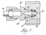
- the assembly 10 further includes fitting means, generally indicated at 40, threadably engageable with the second apertures 22 for connection to a conduit 42.
- the fitting means 40 comprises a fitting 44 having a central passageway 46 to allow lubricant and air to be mixed in the central passageway 46 before exiting the support block 14.
- the first passageway 24 communicates with the central passageway 46.
- a diagonal passageway 48 interconnects the first passageway 24 and central passageway 46.
- Third passageway 38 communicates with the central passageway 46.
- a ball check valve 50 is disposed in the central passageway 46 between the end of the third passageway 38 and diagonal passageway 48.
- a first alternate embodiment of the fitting 40 wherein like parts have prime numerals, is generally indicated at 40′.
- the fitting 44′ may have solid or closed at the end 51 to prevent air from entering the central passageway 46′ from the third passageway 38 and from being mixed with the lubricant and to allow solely lubricant to exit the fitting 44′.
- the ball check valve 50 would be eliminated.
- the assembly 10 may include a plug means threadably engageable with the second aperture 22 for preventing lubricant and air from exiting the support block 14.
- the plug means comprises a plug member 52 thereadably engageable with the second aperture 22.
- the plug member 52 has a closed end 54 to prevent air from being discharged from the third passageway 38 into the second aperture 22.
- the plug member 52 includes an annular shoulder 56 closing the first passageway 24 to prevent lubricant from entering the second aperture 22.
- the assembly 10 also includes a conduit 42 having one end connected to the fitting means 40, 40′.
- the assembly 10 further includes nozzle means 54, 54′ connected to the other end of the conduit 42 for distributing or spraying the lubricant or lubricant/air mixture on the object.
- Lubricant enters the assembly 10 at first aperture 20.
- the first valve member 30 is shifted to one side to exhaust a metered amount of lubricant from the support block 14.
- the valve member 30′ in the second or intermediate support block 14′ shifts to the same side to distribute or exhaust a second metered amount of lubricant from the second support block 14′.
- This cycle is repeated for the plurality of individual support blocks connected together.
- the air is mixed with the lubricant internally within the central passageway 46 of the fitting 44 at second passageway 26 before exiting the support block 14.
Landscapes
- Engineering & Computer Science (AREA)
- General Engineering & Computer Science (AREA)
- Mechanical Engineering (AREA)
- Chemical & Material Sciences (AREA)
- Combustion & Propulsion (AREA)
- Oil, Petroleum & Natural Gas (AREA)
- Nozzles (AREA)
- Mounting, Exchange, And Manufacturing Of Dies (AREA)
- Rolling Contact Bearings (AREA)
Applications Claiming Priority (2)
| Application Number | Priority Date | Filing Date | Title |
|---|---|---|---|
| US11699687A | 1987-11-05 | 1987-11-05 | |
| US116996 | 1987-11-05 |
Publications (2)
| Publication Number | Publication Date |
|---|---|
| EP0314969A2 true EP0314969A2 (fr) | 1989-05-10 |
| EP0314969A3 EP0314969A3 (fr) | 1989-10-04 |
Family
ID=22370470
Family Applications (1)
| Application Number | Title | Priority Date | Filing Date |
|---|---|---|---|
| EP88117228A Withdrawn EP0314969A3 (fr) | 1987-11-05 | 1988-10-17 | Bloc pour des distributeurs à air-huile progressifs en série |
Country Status (1)
| Country | Link |
|---|---|
| EP (1) | EP0314969A3 (fr) |
Cited By (8)
| Publication number | Priority date | Publication date | Assignee | Title |
|---|---|---|---|---|
| DE4316581A1 (de) * | 1993-05-18 | 1994-11-24 | Lincoln Gmbh | Rückschlagventil |
| EP0878658A1 (fr) | 1997-05-14 | 1998-11-18 | Joseph Vögele AG | Distributeur progressif pour des systèmes de graissage |
| EP1275895A1 (fr) * | 2001-07-11 | 2003-01-15 | Dropsa S.P.A. | Dispositif de lubrification pour alimenter en quantités mesurées de lubrifiant plusieurs dispositifs |
| WO2009134715A2 (fr) | 2008-04-30 | 2009-11-05 | Graco Minnesota Inc. | Dispositif de lubrification air / huile |
| ITMI20092084A1 (it) * | 2009-11-26 | 2011-05-27 | Dropsa Spa | "dispositivo di lubrificazione minimale" |
| WO2011149550A2 (fr) | 2010-05-27 | 2011-12-01 | Graco Minnesota Inc. | Raccord à orifice transversal et double joint d'étanchéité pour vanne de répartition à système progressif |
| US8844681B2 (en) | 2009-11-26 | 2014-09-30 | Dropsa S.P.A. | Device for oil or fluid grease lubrication |
| AU2015203532B2 (en) * | 2010-05-27 | 2017-02-23 | Graco Minnesota Inc. | Double-sealed cross-port fitting for series progressive divider valve |
Family Cites Families (3)
| Publication number | Priority date | Publication date | Assignee | Title |
|---|---|---|---|---|
| US2926858A (en) * | 1958-04-21 | 1960-03-01 | Production Specialists | Spraying apparatus |
| US3467222A (en) * | 1967-02-14 | 1969-09-16 | Eaton Yale & Towne | Progressive lubricant feeder with cross porting |
| GB1438681A (en) * | 1973-07-11 | 1976-06-09 | Lumatic Ltd | Lubrication systems |
-
1988
- 1988-10-17 EP EP88117228A patent/EP0314969A3/fr not_active Withdrawn
Cited By (25)
| Publication number | Priority date | Publication date | Assignee | Title |
|---|---|---|---|---|
| EP0625660A3 (fr) * | 1993-05-18 | 1995-03-15 | Lincoln Gmbh | Soupape de retenue. |
| US5443091A (en) * | 1993-05-18 | 1995-08-22 | Lincoln Gmbh | Non-return valve with improved line connecting mechanism |
| DE4316581A1 (de) * | 1993-05-18 | 1994-11-24 | Lincoln Gmbh | Rückschlagventil |
| EP0878658A1 (fr) | 1997-05-14 | 1998-11-18 | Joseph Vögele AG | Distributeur progressif pour des systèmes de graissage |
| EP1275895A1 (fr) * | 2001-07-11 | 2003-01-15 | Dropsa S.P.A. | Dispositif de lubrification pour alimenter en quantités mesurées de lubrifiant plusieurs dispositifs |
| EP2283211A4 (fr) * | 2008-04-30 | 2011-09-14 | Graco Minnesota Inc | Dispositif de lubrification air / huile |
| WO2009134715A2 (fr) | 2008-04-30 | 2009-11-05 | Graco Minnesota Inc. | Dispositif de lubrification air / huile |
| JP2011526343A (ja) * | 2008-04-30 | 2011-10-06 | グラコ ミネソタ インコーポレイテッド | 空気式油潤滑装置 |
| US8844681B2 (en) | 2009-11-26 | 2014-09-30 | Dropsa S.P.A. | Device for oil or fluid grease lubrication |
| EP2333395A1 (fr) * | 2009-11-26 | 2011-06-15 | DROPSA S.p.A. | Dispositif de graissage |
| US9127808B2 (en) | 2009-11-26 | 2015-09-08 | Dropsa S.P.A. | Minimal lubrication device |
| ITMI20092084A1 (it) * | 2009-11-26 | 2011-05-27 | Dropsa Spa | "dispositivo di lubrificazione minimale" |
| CN102939490A (zh) * | 2010-05-27 | 2013-02-20 | 格瑞克明尼苏达有限公司 | 用于串联递进式分配阀的交叉式端口结构 |
| WO2011149550A3 (fr) * | 2010-05-27 | 2012-04-19 | Graco Minnesota Inc. | Raccord à orifice transversal et double joint d'étanchéité pour vanne de répartition à système progressif |
| CN102971563A (zh) * | 2010-05-27 | 2013-03-13 | 格瑞克明尼苏达有限公司 | 用于串联递进式分配阀的双密封交叉式管接头 |
| CN102971563B (zh) * | 2010-05-27 | 2014-07-30 | 格瑞克明尼苏达有限公司 | 用于串联递进式分配阀的双密封交叉式管接头 |
| US8807170B2 (en) | 2010-05-27 | 2014-08-19 | Graco Minnesota Inc. | Cross-porting configuration for series progressive divider valve |
| CN102939490B (zh) * | 2010-05-27 | 2014-09-03 | 格瑞克明尼苏达有限公司 | 用于串联递进式分配阀的交叉式端口结构 |
| WO2011149547A3 (fr) * | 2010-05-27 | 2012-04-05 | Graco Minnesota Inc. | Configuration de groupe d'orifices transversal pour soupape de division progressive série |
| US8887767B2 (en) | 2010-05-27 | 2014-11-18 | Graco Minnesota Inc. | Double-sealed cross-port fitting for series progressive divider valve |
| AU2011258888B2 (en) * | 2010-05-27 | 2015-04-09 | Graco Minnesota Inc. | Cross-porting configuration for series progressive divider valve |
| WO2011149550A2 (fr) | 2010-05-27 | 2011-12-01 | Graco Minnesota Inc. | Raccord à orifice transversal et double joint d'étanchéité pour vanne de répartition à système progressif |
| EP2577133A4 (fr) * | 2010-05-27 | 2015-12-02 | Graco Minnesota Inc | Configuration de groupe d'orifices transversal pour soupape de division progressive série |
| EP2577136A4 (fr) * | 2010-05-27 | 2015-12-09 | Graco Minnesota Inc | Raccord à orifice transversal et double joint d'étanchéité pour vanne de répartition à système progressif |
| AU2015203532B2 (en) * | 2010-05-27 | 2017-02-23 | Graco Minnesota Inc. | Double-sealed cross-port fitting for series progressive divider valve |
Also Published As
| Publication number | Publication date |
|---|---|
| EP0314969A3 (fr) | 1989-10-04 |
Similar Documents
| Publication | Publication Date | Title |
|---|---|---|
| EP0314969A2 (fr) | Bloc pour des distributeurs à air-huile progressifs en série | |
| US5810115A (en) | Pressure bypass accessory for a series progressive divider valve | |
| EP1299624B1 (fr) | Dispositif de refroidissement d'un moteur thermique | |
| DE10354843A1 (de) | Verbesserte Ammoniak-Einspeisungssteuerung zur selektiven katalytischen Reduktion | |
| EP0574442A1 (fr) | Systeme pour l'alimentation en gaz inerte d'une pompe a vide a etages multiples fonctionnant a sec. | |
| EP0224774B1 (fr) | Distributeur progressif pour lubrifiant | |
| EP1194694B1 (fr) | Dispositif de pompage pour le refoulement de grandes quantites de liquide | |
| DE1902587A1 (de) | Schmiermittelverteilervorrichtung | |
| DE69828232T2 (de) | Vorrichtung zur Verhinderung des Lösens eines Bolzens | |
| EP0220179B1 (fr) | Dispositif pour l'injection continue de carburant | |
| DE202017101250U1 (de) | Pumpe sowie Schmiersystem | |
| DE10314781A1 (de) | Modulare Kraftstoffeinspritzeinheit | |
| DE2821161A1 (de) | Geteilte regelstange | |
| EP4298369B1 (fr) | Distributeur progressif | |
| US2308865A (en) | Lubricating system | |
| DE1809954B2 (de) | Ventilausbildung und deren Anordnung im Zylinderkopf einer Kolbenpumpe | |
| DE69408927T2 (de) | Vorrichtung zur Verteilung von Brennstoff über mehrere Einspritzdüse | |
| DE102015220960B4 (de) | Öl-Luft-Schmierverteiler | |
| DE19909548A1 (de) | Kraftstoffeinspritzventil | |
| EP0878658B1 (fr) | Distributeur progressif pour des systèmes de graissage | |
| DE2917863A1 (de) | Progressivverteiler | |
| US3543881A (en) | Fluid distributor means | |
| US4393958A (en) | Progressive-central lubrication system | |
| EP0967436A3 (fr) | Brûleur en cascade | |
| EP0981008B1 (fr) | Repartiteur d'huile |
Legal Events
| Date | Code | Title | Description |
|---|---|---|---|
| PUAI | Public reference made under article 153(3) epc to a published international application that has entered the european phase |
Free format text: ORIGINAL CODE: 0009012 |
|
| AK | Designated contracting states |
Kind code of ref document: A2 Designated state(s): AT BE DE FR GB IT NL SE |
|
| PUAL | Search report despatched |
Free format text: ORIGINAL CODE: 0009013 |
|
| AK | Designated contracting states |
Kind code of ref document: A3 Designated state(s): AT BE DE FR GB IT NL SE |
|
| 17P | Request for examination filed |
Effective date: 19891123 |
|
| 17Q | First examination report despatched |
Effective date: 19910418 |
|
| STAA | Information on the status of an ep patent application or granted ep patent |
Free format text: STATUS: THE APPLICATION HAS BEEN WITHDRAWN |
|
| 18W | Application withdrawn |
Withdrawal date: 19910702 |
|
| R18W | Application withdrawn (corrected) |
Effective date: 19910702 |