EP0314977A2 - Dispositif pour la production d'énergie - Google Patents
Dispositif pour la production d'énergie Download PDFInfo
- Publication number
- EP0314977A2 EP0314977A2 EP88117299A EP88117299A EP0314977A2 EP 0314977 A2 EP0314977 A2 EP 0314977A2 EP 88117299 A EP88117299 A EP 88117299A EP 88117299 A EP88117299 A EP 88117299A EP 0314977 A2 EP0314977 A2 EP 0314977A2
- Authority
- EP
- European Patent Office
- Prior art keywords
- fuel
- reaction chamber
- storage container
- protective gas
- strand
- Prior art date
- Legal status (The legal status is an assumption and is not a legal conclusion. Google has not performed a legal analysis and makes no representation as to the accuracy of the status listed.)
- Granted
Links
- 239000000446 fuel Substances 0.000 claims abstract description 41
- 238000006243 chemical reaction Methods 0.000 claims abstract description 38
- 230000001681 protective effect Effects 0.000 claims abstract description 13
- 238000000926 separation method Methods 0.000 claims abstract description 7
- 239000007787 solid Substances 0.000 claims abstract description 7
- 238000004519 manufacturing process Methods 0.000 claims abstract 2
- 230000001133 acceleration Effects 0.000 claims description 12
- CURLTUGMZLYLDI-UHFFFAOYSA-N Carbon dioxide Chemical compound O=C=O CURLTUGMZLYLDI-UHFFFAOYSA-N 0.000 claims description 10
- 238000001816 cooling Methods 0.000 claims description 9
- XQHAGELNRSUUGU-UHFFFAOYSA-M lithium chlorate Chemical compound [Li+].[O-]Cl(=O)=O XQHAGELNRSUUGU-UHFFFAOYSA-M 0.000 claims description 8
- 229910002092 carbon dioxide Inorganic materials 0.000 claims description 5
- 239000001569 carbon dioxide Substances 0.000 claims description 5
- XLYOFNOQVPJJNP-UHFFFAOYSA-N water Substances O XLYOFNOQVPJJNP-UHFFFAOYSA-N 0.000 claims description 5
- WHXSMMKQMYFTQS-UHFFFAOYSA-N Lithium Chemical compound [Li] WHXSMMKQMYFTQS-UHFFFAOYSA-N 0.000 claims description 4
- 229910052744 lithium Inorganic materials 0.000 claims description 4
- 238000002347 injection Methods 0.000 claims description 3
- 239000007924 injection Substances 0.000 claims description 3
- 239000007789 gas Substances 0.000 description 10
- WMFOQBRAJBCJND-UHFFFAOYSA-M Lithium hydroxide Chemical compound [Li+].[OH-] WMFOQBRAJBCJND-UHFFFAOYSA-M 0.000 description 4
- 239000000498 cooling water Substances 0.000 description 3
- 238000002485 combustion reaction Methods 0.000 description 2
- KWGKDLIKAYFUFQ-UHFFFAOYSA-M lithium chloride Chemical compound [Li+].[Cl-] KWGKDLIKAYFUFQ-UHFFFAOYSA-M 0.000 description 2
- 239000002245 particle Substances 0.000 description 2
- 239000004449 solid propellant Substances 0.000 description 2
- 230000000712 assembly Effects 0.000 description 1
- 238000000429 assembly Methods 0.000 description 1
- 239000007795 chemical reaction product Substances 0.000 description 1
- 238000005516 engineering process Methods 0.000 description 1
- 230000003628 erosive effect Effects 0.000 description 1
- XGZVUEUWXADBQD-UHFFFAOYSA-L lithium carbonate Chemical compound [Li+].[Li+].[O-]C([O-])=O XGZVUEUWXADBQD-UHFFFAOYSA-L 0.000 description 1
- 229910052808 lithium carbonate Inorganic materials 0.000 description 1
- 239000007800 oxidant agent Substances 0.000 description 1
- 235000011837 pasties Nutrition 0.000 description 1
- 230000000149 penetrating effect Effects 0.000 description 1
- 238000010248 power generation Methods 0.000 description 1
Images
Classifications
-
- C—CHEMISTRY; METALLURGY
- C01—INORGANIC CHEMISTRY
- C01D—COMPOUNDS OF ALKALI METALS, i.e. LITHIUM, SODIUM, POTASSIUM, RUBIDIUM, CAESIUM, OR FRANCIUM
- C01D15/00—Lithium compounds
- C01D15/04—Halides
-
- B—PERFORMING OPERATIONS; TRANSPORTING
- B63—SHIPS OR OTHER WATERBORNE VESSELS; RELATED EQUIPMENT
- B63G—OFFENSIVE OR DEFENSIVE ARRANGEMENTS ON VESSELS; MINE-LAYING; MINE-SWEEPING; SUBMARINES; AIRCRAFT CARRIERS
- B63G8/00—Underwater vessels, e.g. submarines; Equipment specially adapted therefor
- B63G8/08—Propulsion
-
- C—CHEMISTRY; METALLURGY
- C06—EXPLOSIVES; MATCHES
- C06D—MEANS FOR GENERATING SMOKE OR MIST; GAS-ATTACK COMPOSITIONS; GENERATION OF GAS FOR BLASTING OR PROPULSION (CHEMICAL PART)
- C06D5/00—Generation of pressure gas, e.g. for blasting cartridges, starting cartridges, rockets
- C06D5/10—Generation of pressure gas, e.g. for blasting cartridges, starting cartridges, rockets by reaction of solids with liquids
-
- F—MECHANICAL ENGINEERING; LIGHTING; HEATING; WEAPONS; BLASTING
- F02—COMBUSTION ENGINES; HOT-GAS OR COMBUSTION-PRODUCT ENGINE PLANTS
- F02B—INTERNAL-COMBUSTION PISTON ENGINES; COMBUSTION ENGINES IN GENERAL
- F02B43/00—Engines characterised by operating on gaseous fuels; Plants including such engines
- F02B43/10—Engines or plants characterised by use of other specific gases, e.g. acetylene, oxyhydrogen
-
- F—MECHANICAL ENGINEERING; LIGHTING; HEATING; WEAPONS; BLASTING
- F02—COMBUSTION ENGINES; HOT-GAS OR COMBUSTION-PRODUCT ENGINE PLANTS
- F02K—JET-PROPULSION PLANTS
- F02K9/00—Rocket-engine plants, i.e. plants carrying both fuel and oxidant therefor; Control thereof
- F02K9/72—Rocket-engine plants, i.e. plants carrying both fuel and oxidant therefor; Control thereof using liquid and solid propellants, i.e. hybrid rocket-engine plants
-
- F—MECHANICAL ENGINEERING; LIGHTING; HEATING; WEAPONS; BLASTING
- F42—AMMUNITION; BLASTING
- F42B—EXPLOSIVE CHARGES, e.g. FOR BLASTING, FIREWORKS, AMMUNITION
- F42B19/00—Marine torpedoes, e.g. launched by surface vessels or submarines; Sea mines having self-propulsion means
- F42B19/12—Propulsion specially adapted for torpedoes
- F42B19/14—Propulsion specially adapted for torpedoes by compressed-gas motors
- F42B19/20—Propulsion specially adapted for torpedoes by compressed-gas motors characterised by the composition of propulsive gas; Manufacture or heating thereof in torpedoes
-
- Y—GENERAL TAGGING OF NEW TECHNOLOGICAL DEVELOPMENTS; GENERAL TAGGING OF CROSS-SECTIONAL TECHNOLOGIES SPANNING OVER SEVERAL SECTIONS OF THE IPC; TECHNICAL SUBJECTS COVERED BY FORMER USPC CROSS-REFERENCE ART COLLECTIONS [XRACs] AND DIGESTS
- Y02—TECHNOLOGIES OR APPLICATIONS FOR MITIGATION OR ADAPTATION AGAINST CLIMATE CHANGE
- Y02T—CLIMATE CHANGE MITIGATION TECHNOLOGIES RELATED TO TRANSPORTATION
- Y02T10/00—Road transport of goods or passengers
- Y02T10/10—Internal combustion engine [ICE] based vehicles
- Y02T10/30—Use of alternative fuels, e.g. biofuels
Definitions
- the invention relates to a device for chemothermal energy generation using a fuel strand containing solid components, consisting of a storage container, a conveyor system and a reaction chamber.
- the object of the invention is to further improve an energy generating device which is designed for the use of a strand-like fuel, both in terms of its energy balance and in terms of its operational reliability.
- the invention solves this problem by providing that the delivery path of the fuel train is surrounded by a pressure-tight envelope connected to both the storage container and the reaction chamber and that the storage container and the region of the delivery path are acted upon by a protective gas, the pressure of which at least is the same as the operating pressure in the reaction chamber. In this way it is avoided that the combustion chamber gases generated during energy generation can flow back into the fuel supply system.
- the cooling water coming from the cooling device is injected into the reaction chamber and thus also used as a fuel component, there is a further improvement in the energy balance.
- the protective gas is selected such that leakage quantities that flow into the reaction chamber react with a chemical reaction with the reaction products of the fuels and are bound, so that water-insoluble gases do not arise.
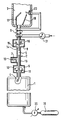
- the figure shows a schematic representation of a device for power generation, which essentially consists of three main assemblies, namely a storage container 1, a conveyor system 2 and a reaction chamber 3.
- the fuel which consists of solid particles embedded in a carrier strand, is in the form of a roll stored.
- the fuel line 4 is fed to the reaction chamber 3 via a conveyor path 5, along which a mechanical drive unit (conveyor device) 6, a separation unit 7 and an acceleration unit 8 are arranged.
- a mechanical drive unit (conveyor device) 6 along which a mechanical drive unit (conveyor device) 6, a separation unit 7 and an acceleration unit 8 are arranged.
- a cooling device 9 arranged along the conveyor path, shortly before entering reaction chamber 3, still a cooling device 9 arranged.
- the entire conveying path 5, including the drive unit 6, the separation unit 7 and the acceleration unit 8, is located in a pressure-tight envelope 10, which is connected at one end to the storage container 1 and at the other end to the reaction chamber 3.
- the mechanical drive unit 6 consists of conveyor rollers 11 and 12 which are in engagement with the fuel line 4 and which impart a movement component to the fuel chamber 4 in the direction of the reaction chamber 3.
- a separating knife 13 is movably held in the direction of the fuel strand 4, with the aid of which the strand can be divided into individual sections 14.
- These sections 14 then reach the acceleration unit 8, in which two spring-loaded acceleration levers 15 and 16 act on them and impart an acceleration in the direction of the reaction chamber. There, the sections 14 collide with a deflection device 17, from where they reach a collecting plate 18.
- the storage container 1 like the entire conveying device located in the casing 10, is supplied with protective gas by a protective gas storage container 19 via a pressure control valve 20.
- the pressure level is set so that it corresponds to that in the reaction chamber 3 or is slightly above it.
- a volume compensation for used fuel is carried out, and leakage losses that occur during the fuel transport into the reaction chamber are compensated for.
- the entire fuel delivery system practically has a pneumatic seal against the atmosphere in the reaction chamber. This prevents heat transport by mass transport from the reaction chamber into the fuel delivery system.
- the cooling device 9 consists of a tube through which water flows, which is acted upon by a cooling water pump 21 and which opens into an injection device 22 which is arranged in the interior of the reaction chamber 3.
- This water cooling in the area of the tubular casing 10 between the acceleration unit 8 and the reaction chamber 3 prevents heat transport from the reaction chamber 3 into the area of the conveyor system 2 as a result of heat conduction via the casing 10.
- a particularly suitable fuel system for the energy generating device described above consists of metallic lithium and crystalline, anhydrous lithium chlorate (LiClO4), the lithium chlorate being present as a filling in a lithium tube that forms the fuel line 4.
- the chemical reaction consists in the combustion of these components with the addition of water according to the equation 8 Li + LiClO4 + 4 H2O ⁇ LiCl + 8 LiOH Carbon dioxide (CO2) can serve as a protective gas in this system, with any leakage amount penetrating into the reaction chamber 3 according to the reaction CO2 + 2 LiOH ⁇ Li2CO3 + H2O be tied off.
- the water of the cooling device which is wholly or partially injected into the reaction chamber 3, takes on the role of an additional fuel component.
Landscapes
- Engineering & Computer Science (AREA)
- Chemical & Material Sciences (AREA)
- Combustion & Propulsion (AREA)
- Mechanical Engineering (AREA)
- General Engineering & Computer Science (AREA)
- Organic Chemistry (AREA)
- Materials Engineering (AREA)
- Chemical Kinetics & Catalysis (AREA)
- Inorganic Chemistry (AREA)
- Aviation & Aerospace Engineering (AREA)
- Physical Or Chemical Processes And Apparatus (AREA)
- Feeding, Discharge, Calcimining, Fusing, And Gas-Generation Devices (AREA)
Applications Claiming Priority (2)
| Application Number | Priority Date | Filing Date | Title |
|---|---|---|---|
| DE3737722A DE3737722C1 (en) | 1987-11-06 | 1987-11-06 | Appliance for energy generation |
| DE3737722 | 1987-11-06 |
Publications (3)
| Publication Number | Publication Date |
|---|---|
| EP0314977A2 true EP0314977A2 (fr) | 1989-05-10 |
| EP0314977A3 EP0314977A3 (en) | 1989-12-27 |
| EP0314977B1 EP0314977B1 (fr) | 1993-06-30 |
Family
ID=6339945
Family Applications (1)
| Application Number | Title | Priority Date | Filing Date |
|---|---|---|---|
| EP88117299A Expired - Lifetime EP0314977B1 (fr) | 1987-11-06 | 1988-10-18 | Dispositif pour la production d'énergie |
Country Status (3)
| Country | Link |
|---|---|
| EP (1) | EP0314977B1 (fr) |
| JP (1) | JPH01237345A (fr) |
| DE (1) | DE3737722C1 (fr) |
Cited By (1)
| Publication number | Priority date | Publication date | Assignee | Title |
|---|---|---|---|---|
| WO2014191588A1 (fr) * | 2013-05-27 | 2014-12-04 | Benito De Paz Ucedo | Centrale de production d'énergie électrique par explosion contrôlée |
Family Cites Families (3)
| Publication number | Priority date | Publication date | Assignee | Title |
|---|---|---|---|---|
| US4129003A (en) * | 1976-03-29 | 1978-12-12 | Q Corporation | Engine operated by a non-polluting recyclable fuel |
| DE3443984A1 (de) * | 1984-12-01 | 1986-06-12 | Erno Raumfahrttechnik Gmbh, 2800 Bremen | Antriebsaggregat zum aussenluftunabhaengigen verbrennen von treibstoffkombinationen |
| US4643166A (en) * | 1984-12-13 | 1987-02-17 | The Garrett Corporation | Steam engine reaction chamber, fuel composition therefore, and method of making and operating same |
-
1987
- 1987-11-06 DE DE3737722A patent/DE3737722C1/de not_active Expired
-
1988
- 1988-10-18 EP EP88117299A patent/EP0314977B1/fr not_active Expired - Lifetime
- 1988-11-01 JP JP63274659A patent/JPH01237345A/ja active Pending
Cited By (1)
| Publication number | Priority date | Publication date | Assignee | Title |
|---|---|---|---|---|
| WO2014191588A1 (fr) * | 2013-05-27 | 2014-12-04 | Benito De Paz Ucedo | Centrale de production d'énergie électrique par explosion contrôlée |
Also Published As
| Publication number | Publication date |
|---|---|
| DE3737722C1 (en) | 1988-11-10 |
| EP0314977B1 (fr) | 1993-06-30 |
| JPH01237345A (ja) | 1989-09-21 |
| EP0314977A3 (en) | 1989-12-27 |
Similar Documents
| Publication | Publication Date | Title |
|---|---|---|
| EP0637987B1 (fr) | Procede et dispositif permettant de separer des melanges gazeux se formant au-dessus de liquides | |
| DE4206803C2 (de) | Verfahren zum Nachfüllen von Halogengas in das Gasreservoir eines Excimer-Lasers | |
| DE2718357A1 (de) | Pyrotechnische einrichtung zum verschliessen einer leitung | |
| DE2165388C2 (de) | Verfahren und Vorrichtung zum Entleeren von Flussiggasspeicherbe haltern | |
| WO1986005198A1 (fr) | Procede d'evacution de particules de residus d'un reacteur de gaseification sous pression | |
| EP0314977B1 (fr) | Dispositif pour la production d'énergie | |
| DE3633683C1 (en) | Engine test chamber (engine test rig, engine test bed) | |
| DE3224608A1 (de) | Verfahren und vorrichtung zur druckgasversorgung | |
| DE102012020811A1 (de) | Druckerhöhungsanlage | |
| DE2558220B2 (de) | Mehrstufige Flüssigtreibstoff-Rakete | |
| EP3549875A1 (fr) | Système d'aération renouvelable pour un corps spatial | |
| EP0128260A1 (fr) | Dispositif de sauvetage pour submersibles | |
| DE2620303C3 (de) | Verfahren und Vorrichtung zum Aushärten von Sandformen oder Sandkernen | |
| DE484064C (de) | Mit fluessigen Betriebsstoffen betriebene Gasrakete | |
| DE859240C (de) | Regelung von Kraftanlagen mit einem Flugkolbentreibdruckgaserzeuger und einer von diesen Gasen angetriebenen Maschine, insbesondere einer Turbine | |
| DE2506612C2 (de) | Verfahren und Vorrichtung zum Bekämpfen von durch Mineralölbestandteilen oder -produkten hervorgerufenen filmförmigen Verunreinigungen an der Erdoberfläche, insbesondere an Oberflächengewässern | |
| DE19545728A1 (de) | Vorrichtung zur LOX-Tank-Bedrückung einer Hybridrakete auf der Basis des Einspritzsystems | |
| EP0468144B1 (fr) | Procédé pour la préparation d'un combustible | |
| DE3209251C2 (de) | Verfahren zum Hindrängen von in einem Behälter im schwerelosen Zustand befindlicher Flüssigkeit zu Ausflußöffnungen hin sowie Vorrichtung zur Durchführung des Verfahrens | |
| DE2746382A1 (de) | Tintenstrahl-schreibsystem | |
| DE3443984C2 (fr) | ||
| DE9205925U1 (de) | Vorrichtung zur Trennung von über Flüssigkeiten entstehenden Gasgemischen | |
| CH650175A5 (de) | Verfahren und einrichtung zum dosieren von brennstoffen bei der herstellung von giessereisandformen. | |
| DE1910405A1 (de) | Verfahren und Einrichtung zum Herstellen von aus mindestens drei Komponenten bestehenden Schutzgasgemischen fuer das Schweissen und Schneiden | |
| DE7824726U1 (de) | Vorrichtung zum Füllen von Aerosolbehältern |
Legal Events
| Date | Code | Title | Description |
|---|---|---|---|
| PUAI | Public reference made under article 153(3) epc to a published international application that has entered the european phase |
Free format text: ORIGINAL CODE: 0009012 |
|
| AK | Designated contracting states |
Kind code of ref document: A2 Designated state(s): FR GB IT |
|
| 17P | Request for examination filed |
Effective date: 19890408 |
|
| PUAL | Search report despatched |
Free format text: ORIGINAL CODE: 0009013 |
|
| AK | Designated contracting states |
Kind code of ref document: A3 Designated state(s): FR GB IT |
|
| RHK1 | Main classification (correction) |
Ipc: C06D 5/10 |
|
| 17Q | First examination report despatched |
Effective date: 19910801 |
|
| GRAA | (expected) grant |
Free format text: ORIGINAL CODE: 0009210 |
|
| K1C1 | Correction of patent application (title page) published |
Effective date: 19890510 |
|
| AK | Designated contracting states |
Kind code of ref document: B1 Designated state(s): FR GB IT |
|
| PG25 | Lapsed in a contracting state [announced via postgrant information from national office to epo] |
Ref country code: IT Free format text: LAPSE BECAUSE OF FAILURE TO SUBMIT A TRANSLATION OF THE DESCRIPTION OR TO PAY THE FEE WITHIN THE PRESCRIBED TIME-LIMIT;WARNING: LAPSES OF ITALIAN PATENTS WITH EFFECTIVE DATE BEFORE 2007 MAY HAVE OCCURRED AT ANY TIME BEFORE 2007. THE CORRECT EFFECTIVE DATE MAY BE DIFFERENT FROM THE ONE RECORDED. Effective date: 19930630 Ref country code: GB Effective date: 19930630 Ref country code: FR Effective date: 19930630 |
|
| EN | Fr: translation not filed | ||
| GBV | Gb: ep patent (uk) treated as always having been void in accordance with gb section 77(7)/1977 [no translation filed] |
Effective date: 19930630 |
|
| PLBE | No opposition filed within time limit |
Free format text: ORIGINAL CODE: 0009261 |
|
| STAA | Information on the status of an ep patent application or granted ep patent |
Free format text: STATUS: NO OPPOSITION FILED WITHIN TIME LIMIT |
|
| 26N | No opposition filed |