EP0315028A1 - Procédé de synchronisation d'émetteurs, dispositif de contrôle et émetteurs réalisant le procédé ainsi que l'application du procédé - Google Patents
Procédé de synchronisation d'émetteurs, dispositif de contrôle et émetteurs réalisant le procédé ainsi que l'application du procédé Download PDFInfo
- Publication number
- EP0315028A1 EP0315028A1 EP88117745A EP88117745A EP0315028A1 EP 0315028 A1 EP0315028 A1 EP 0315028A1 EP 88117745 A EP88117745 A EP 88117745A EP 88117745 A EP88117745 A EP 88117745A EP 0315028 A1 EP0315028 A1 EP 0315028A1
- Authority
- EP
- European Patent Office
- Prior art keywords
- transmitter
- time
- control device
- group
- transmitters
- Prior art date
- Legal status (The legal status is an assumption and is not a legal conclusion. Google has not performed a legal analysis and makes no representation as to the accuracy of the status listed.)
- Granted
Links
- 238000000034 method Methods 0.000 title claims description 30
- 230000001360 synchronised effect Effects 0.000 claims abstract description 19
- 230000005540 biological transmission Effects 0.000 claims description 18
- 238000010586 diagram Methods 0.000 description 4
- 239000000969 carrier Substances 0.000 description 2
- 230000032683 aging Effects 0.000 description 1
- 238000004891 communication Methods 0.000 description 1
- 230000001934 delay Effects 0.000 description 1
- 238000012544 monitoring process Methods 0.000 description 1
- 230000000737 periodic effect Effects 0.000 description 1
Images

Classifications
-
- G—PHYSICS
- G04—HOROLOGY
- G04G—ELECTRONIC TIME-PIECES
- G04G7/00—Synchronisation
- G04G7/02—Synchronisation by radio
-
- H—ELECTRICITY
- H04—ELECTRIC COMMUNICATION TECHNIQUE
- H04J—MULTIPLEX COMMUNICATION
- H04J3/00—Time-division multiplex systems
- H04J3/02—Details
- H04J3/06—Synchronising arrangements
- H04J3/0635—Clock or time synchronisation in a network
- H04J3/0682—Clock or time synchronisation in a network by delay compensation, e.g. by compensation of propagation delay or variations thereof, by ranging
Definitions
- the invention relates to a method for synchronizing a plurality of transmitters which are connected to a control device provided with a clock, each transmitter being arranged at a known distance from the control device and having a clock to be synchronized.
- the invention further relates to a transmitter control device and a transmitter for performing the method and relates to an application of the method to a radio paging network.
- the problem of synchronization of the transmitters can arise, for example in the case of a local network, in which digital identification codes are sent for the individual call receivers.
- the synchronization relates to the modulation of the transmitters, not to their HF carriers.
- the RF carriers are allowed to run freely and, if necessary, are operated with a certain frequency offset so that no standing waves are formed which lead to "holes" in the coverage area.
- radio devices with several transmitters, these are connected directly to the signal source, e.g. connected to the call center of a paging network.
- the lines are provided with transit time controllers, which allow a certain compensation of the different distances between call center and transmitters.
- a major disadvantage of the method is that the properties of the modulation lines and the devices involved continuously change due to weather influences, temperature and aging. This results in a relatively large effort for the periodic adjustment of the system.
- the invention is therefore based on the object of providing a method of the type mentioned at the outset which does not have the disadvantages mentioned and which permits simple and fast transmitter synchronization.
- This is achieved in that, for the synchronization of the transmitter clocks, an actual time message is emitted by each transmitter, which is received by the control device by means of a radio receiver and whose reception time is determined in the control device and transmitted by the latter to the transmitter, and that in each transmitter the actual time message, time of receipt , Transmission signal transit time between transmitter and receiver and the current transmitter time can be linked in order to obtain the synchronized transmitter time.
- a transmission control device and a transmitter for performing the method is achieved by a transmitter control device with the characterizing features of patent claim 4, or by a transmitter with the characterizing features of patent claim 5.
- two groups of transmitters are first synchronized internally and subsequently with one another.
- the message must be emitted by all transmitters at the same time. Radiated at the same time means that the emission times of the message signal from the transmitting antennas do not exceed a predetermined time difference.
- the message protocols e.g. in the POCSAG format specified by post
- the required time difference or the synchronization accuracy are determined. This is e.g. 1/4 bit, which corresponds to a time difference of 488 ⁇ s at 512 bit / s.
- each message to be sent is provided with a target transmission time, and as soon as the internal clock of each transmitter has reached this time, this message is sent. It is therefore necessary synchronize the transmitter clocks so that the required accuracy can be achieved. It should also be noted that the transmitter signal delay time is different (but known) for each transmitter. Since the clocks (clock oscillators) of the transmitters have different accuracy and different drift, the synchronization must be repeated from time to time.
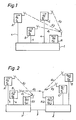
- A, B and C are three radio transmitters.
- the transmitters are connected to a transmission control device 1, which sends 4 control commands and messages to be sent to the transmitters via the lines.
- the aim of the synchronization is that the same modulation signals are always the same Time from the antennas of the two transmitters.
- the control device 1 transmits a command to the transmitters, by means of which they are caused to set their transmitter time to a time before the receiver or control device time; therefore it applies T A ⁇ T R ; T B ⁇ T R ; T C ⁇ T R (1)
- the transmitters are then prompted by the transmission control device (in any order) to emit a synchronization message which contains their local time (actual time).
- the transmitter A emits a synchronization message which contains its actual time T A.
- the receiver R registers its time T R (reception time) at which it received the synchronization message from the transmitter A.
- T R transmission time
- T A - T R is the unknown time difference between the clocks of transmitter A and receiver R.
- the control device transmits the value T R to the transmitter A via the line connection 4.
- the clocks of the other transmitters B and C are corrected with the same steps (in the formulas only the indices A are replaced by B and C, respectively).
- the new times are:
- the transmitters receive a time specification T, which determines the time of transmission.
- the synchronization condition is thus fulfilled for the new times.
- the synchronization process also takes place for a large number of transmitters. It is also irrelevant whether the whole process takes place first for transmitter A and transmitter B subsequently sends its synchronization message or whether all transmitters A, B, C first send their synchronization messages in succession and subsequently in succession or simultaneously the respective times T R to the transmitters be transmitted.
- the method is described with reference to FIG. 2 if the transmitters are divided into several groups, each group having a transmitter control device with a receiver.
- 2 shows two groups of transmitters, the first group with the transmitters A and B and the transmitter control device 1 with the receiver R1 and the second group with the transmitters C and D and the transmitter control device 2 with the receiver R2.
- the method with two groups presupposes that at least one transmitter in one group has a radio connection with the receiver in the other group. In the example shown, it is assumed that this radio connection exists between the transmitter B of the first group and the receiver R2 of the second group.
- there is a communication connection between the two transmitter control devices either via a simple line connection 3 or via a control device common to the transmitter control devices (network control unit 15 3) for the radio network.
- the synchronization is carried out as follows:
- the two groups are each individually synchronized according to the inventive method, as has been explained in connection with FIG. 1.
- the new times are accordingly
- transmitter B sends a synchronization message, which shows the current time (actual time) T B. from transmitter B contains.
- the receiver R2 registers the time T R2 at which it receives this synchronization message.
- T R2 T B , + d B + d5 + T B - T R2 (11)
- T B - T R2 represents the unknown time difference between the clock of transmitter B and the clock of receiver R2.
- the control device 2 then divides the value T R2 . to the control device 1 of the first group and thus to the transmitters A and B.
- the correction value K2 can also be used to correct the clock in transmitter A (or to correct all other transmitters group 1). It should be noted, however, that in this case of group synchronization, only the signal delay value (d B ) of the one transmitter (B) sending the synchronization message is included in the correction value. The other transmitters in the first group will not run exactly in sync.
- the new times for Group 1 channels are:
- the synchronization condition is therefore exactly fulfilled for transmitters B, C and D.
- the remaining error (d A - d B ) at transmitter A is only minor, since it consists of the difference between small signal delays of a similar magnitude. Furthermore, these signal propagation times are generally known, and the difference could therefore also be compensated for.
- T B ' which is primarily only known in the transmitter B.
- Fig. 3 shows the block diagram of a paging system in which the method is preferably applied.
- the paging system essentially consists of a paging terminal 14 connected to the public telephone network 13 and the paging network.
- the paging network is composed of a network control unit 15, a plurality of transmitter group controllers 16 connected thereto and a plurality of transmitter stations 17.
- the transmitter stations 17 are combined in groups and each connected to the transmitter group control device 16 of this group.
- the transmitter stations are in turn divided into an interface (TSI) and the actual transmitter.
- TSI interface
- the paging center forms the interface to the public telephone network. It manages the subscriber data and converts the incoming calls into serial data streams (e.g. in the aforementioned POCSAG format).
- the network is structured hierarchically.
- the individual units are connected to each other via modem lines, on which they communicate with one another in purely digital form. Commands, messages about the system status and, if necessary, alarm messages are exchanged.
- All call reports are buffered both in the network control unit and in the transmitter group control devices 16 and TSI, and there is no direct connection between a call report arrival time in the transmitter station and the time it was broadcast by the transmitter.
- the call message contains the code information for the call receivers, not shown, who are in the area of the paging network.
- the transmitter group control device is additionally provided with a receiver which operates on the frequency of the transmitters.
- the transmitters additionally have a circuit for determining the correction value and correspondingly adapting their - already existing - clock. This circuit is usually implemented by the transmitter's microprocessor control.
- Fig. 4 shows a block diagram of a transmitter group control device.
- the controlling microprocessor 6, storage means 7, an initialization and monitoring circuit 8 and - via an interface 9 - the receiver 10 are connected to their connecting bus 5.
- serial interfaces 11 and modems 12 are provided, by means of which the control device is connected via telephone lines to the transmitters 17 on the one hand and to the network control unit 15 on the other hand.
Landscapes
- Physics & Mathematics (AREA)
- General Physics & Mathematics (AREA)
- Engineering & Computer Science (AREA)
- Computer Networks & Wireless Communication (AREA)
- Signal Processing (AREA)
- Mobile Radio Communication Systems (AREA)
- Synchronisation In Digital Transmission Systems (AREA)
- Selective Calling Equipment (AREA)
- Radar Systems Or Details Thereof (AREA)
- Photoreceptors In Electrophotography (AREA)
- Electric Clocks (AREA)
- Facsimiles In General (AREA)
Applications Claiming Priority (2)
| Application Number | Priority Date | Filing Date | Title |
|---|---|---|---|
| CH425087A CH670545GA3 (fr) | 1987-10-28 | 1987-10-28 | |
| CH4250/87 | 1987-10-28 |
Publications (2)
| Publication Number | Publication Date |
|---|---|
| EP0315028A1 true EP0315028A1 (fr) | 1989-05-10 |
| EP0315028B1 EP0315028B1 (fr) | 1991-11-21 |
Family
ID=4272603
Family Applications (1)
| Application Number | Title | Priority Date | Filing Date |
|---|---|---|---|
| EP88117745A Expired - Lifetime EP0315028B1 (fr) | 1987-10-28 | 1988-10-25 | Procédé de synchronisation d'émetteurs, dispositif de contrôle et émetteurs réalisant le procédé ainsi que l'application du procédé |
Country Status (5)
| Country | Link |
|---|---|
| EP (1) | EP0315028B1 (fr) |
| AT (1) | ATE69657T1 (fr) |
| CH (1) | CH670545GA3 (fr) |
| DE (1) | DE3866334D1 (fr) |
| ES (1) | ES2027364T3 (fr) |
Cited By (3)
| Publication number | Priority date | Publication date | Assignee | Title |
|---|---|---|---|---|
| EP0702464A1 (fr) * | 1994-09-14 | 1996-03-20 | Racotek, Inc. | Système de transmission de données avec synchronisation du temps |
| WO1996017278A1 (fr) * | 1994-11-29 | 1996-06-06 | Gpt Limited | Synchronisation d'horloges |
| WO1998014842A1 (fr) * | 1996-10-03 | 1998-04-09 | H.P.M. Technologies Pty. Ltd. | Synchronisation d'horloge par rapport a une heure de reference |
Families Citing this family (1)
| Publication number | Priority date | Publication date | Assignee | Title |
|---|---|---|---|---|
| US7286624B2 (en) * | 2003-07-03 | 2007-10-23 | Navcom Technology Inc. | Two-way RF ranging system and method for local positioning |
Citations (4)
| Publication number | Priority date | Publication date | Assignee | Title |
|---|---|---|---|---|
| EP0084165A1 (fr) * | 1981-12-25 | 1983-07-27 | Nec Corporation | Système pour calibrer à distance le temps d'un satellite |
| CA1158739A (fr) * | 1980-04-30 | 1983-12-13 | William Rodman | Systeme de synchronisation pour reseau reparti |
| FR2564668A1 (fr) * | 1984-05-15 | 1985-11-22 | Thomson Csf | Procede de transmission d'informations synchrone et decentralise, et reseau de transmission d'informations utilisant ce procede |
| EP0253096A2 (fr) * | 1986-05-20 | 1988-01-20 | Mitsubishi Denki Kabushiki Kaisha | Procédé de synchronisation des horloges dans un système de transmission de données |
-
1987
- 1987-10-28 CH CH425087A patent/CH670545GA3/de not_active IP Right Cessation
-
1988
- 1988-10-25 ES ES198888117745T patent/ES2027364T3/es not_active Expired - Lifetime
- 1988-10-25 AT AT88117745T patent/ATE69657T1/de not_active IP Right Cessation
- 1988-10-25 DE DE8888117745T patent/DE3866334D1/de not_active Expired - Fee Related
- 1988-10-25 EP EP88117745A patent/EP0315028B1/fr not_active Expired - Lifetime
Patent Citations (4)
| Publication number | Priority date | Publication date | Assignee | Title |
|---|---|---|---|---|
| CA1158739A (fr) * | 1980-04-30 | 1983-12-13 | William Rodman | Systeme de synchronisation pour reseau reparti |
| EP0084165A1 (fr) * | 1981-12-25 | 1983-07-27 | Nec Corporation | Système pour calibrer à distance le temps d'un satellite |
| FR2564668A1 (fr) * | 1984-05-15 | 1985-11-22 | Thomson Csf | Procede de transmission d'informations synchrone et decentralise, et reseau de transmission d'informations utilisant ce procede |
| EP0253096A2 (fr) * | 1986-05-20 | 1988-01-20 | Mitsubishi Denki Kabushiki Kaisha | Procédé de synchronisation des horloges dans un système de transmission de données |
Cited By (4)
| Publication number | Priority date | Publication date | Assignee | Title |
|---|---|---|---|---|
| EP0702464A1 (fr) * | 1994-09-14 | 1996-03-20 | Racotek, Inc. | Système de transmission de données avec synchronisation du temps |
| WO1996017278A1 (fr) * | 1994-11-29 | 1996-06-06 | Gpt Limited | Synchronisation d'horloges |
| US6009530A (en) * | 1994-11-29 | 1999-12-28 | Gpt Limited | Real time clock synchronization in a telecommunications network |
| WO1998014842A1 (fr) * | 1996-10-03 | 1998-04-09 | H.P.M. Technologies Pty. Ltd. | Synchronisation d'horloge par rapport a une heure de reference |
Also Published As
| Publication number | Publication date |
|---|---|
| ES2027364T3 (es) | 1992-06-01 |
| CH670545GA3 (fr) | 1989-06-30 |
| DE3866334D1 (de) | 1992-01-02 |
| EP0315028B1 (fr) | 1991-11-21 |
| ATE69657T1 (de) | 1991-12-15 |
Similar Documents
| Publication | Publication Date | Title |
|---|---|---|
| DE3650433T2 (de) | Verfahren zur Synchronisierung von Funksendern in einem lokalen, z.B. nationalen Funknetz. | |
| EP1251646B1 (fr) | Méthode pour la transmission semi-duplex d' informations entre appareils de communication avec répéteurs | |
| DE60030363T2 (de) | Funknetzwerksteuerung | |
| DE68922749T2 (de) | Mobiles Kommunikationssystem. | |
| DE2733503C3 (de) | Bewegliches Nachrichten-Funksystem | |
| DE69936753T2 (de) | Verfahren zur betriebsüberwachung eines zellularen funksystems | |
| DE2523996C3 (de) | Funksprechsystem | |
| DE2615198A1 (de) | Nachrichtenuebertragungssystem zum zweiseitig gerichteten nachrichtenverkehr zwischen einer hauptstation und mehreren unterstationen ueber einen satelliten | |
| DE2050718B2 (de) | Verfahren zur Kommunikation über einen Erdsatelliten mittels Zeitmultiplex und Vorrichtung zur Durchführung des Verfahrens | |
| EP0198448A1 (fr) | Méthode pour la synchronisation de plusieurs émetteurs-récepteurs cadencés | |
| EP0020893B1 (fr) | Réseau radio | |
| DE3133120C2 (fr) | ||
| EP0315028B1 (fr) | Procédé de synchronisation d'émetteurs, dispositif de contrôle et émetteurs réalisant le procédé ainsi que l'application du procédé | |
| DE69209669T2 (de) | Abfrageverfahren in einem drahtlosen Paketdatenübermittlungssystem | |
| EP0326630B1 (fr) | Procédé de transmission de signaux de télécommande sur une seule fréquence porteuse entre émetteurs et récepteurs autonomes fonctionnant en multiplexage par répartition dans le temps et dispositif pour la mise en oeuvre du procédé | |
| DE29908608U1 (de) | Netzwerk sowie Koppelgerät zur Verbindung zweier Segmente in einem derartigen Netzwerk und Netzwerkteilnehmer | |
| EP0118710B1 (fr) | Dispositif de synchronisation pour les signaux utiles d'un système de radiodiffusion sur fréquence commune | |
| EP0448927A1 (fr) | Procédé de transmission d'informations en temps discret | |
| DE69637421T2 (de) | Verfahren für ein Datenbussystem mit Mitteln zur Ressourcensteuerung und Übertragungsstation | |
| EP0536539B1 (fr) | Réseau d'appel radio pour la transmission de signaux d'appel radio relatifs aux abonnés et méthode pour son exploitation | |
| DE2410380A1 (de) | Ortungssystem mit mehr als zwei ortungsgeraeten | |
| DE19701175B4 (de) | Verfahren zur Signalisierung | |
| EP0111164A1 (fr) | Système radio | |
| EP0086865A2 (fr) | Procédé de transmission radio d'informations digitales à l'aide d'une fréquence de transmission | |
| DE69112927T2 (de) | Verfahren zur Regelung der Sendeleistung von Endstationen in einem Zeitgetrenntlage-Übertragungsnetzwerk. |
Legal Events
| Date | Code | Title | Description |
|---|---|---|---|
| PUAI | Public reference made under article 153(3) epc to a published international application that has entered the european phase |
Free format text: ORIGINAL CODE: 0009012 |
|
| AK | Designated contracting states |
Kind code of ref document: A1 Designated state(s): AT BE DE ES FR GB GR IT LU NL SE |
|
| 17P | Request for examination filed |
Effective date: 19891102 |
|
| 17Q | First examination report despatched |
Effective date: 19901102 |
|
| RAP1 | Party data changed (applicant data changed or rights of an application transferred) |
Owner name: FIRMA ERIKA KOECHLER |
|
| GRAA | (expected) grant |
Free format text: ORIGINAL CODE: 0009210 |
|
| AK | Designated contracting states |
Kind code of ref document: B1 Designated state(s): AT BE DE ES FR GB GR IT LU NL SE |
|
| PG25 | Lapsed in a contracting state [announced via postgrant information from national office to epo] |
Ref country code: GR Free format text: LAPSE BECAUSE OF FAILURE TO SUBMIT A TRANSLATION OF THE DESCRIPTION OR TO PAY THE FEE WITHIN THE PRESCRIBED TIME-LIMIT Effective date: 19911121 |
|
| REF | Corresponds to: |
Ref document number: 69657 Country of ref document: AT Date of ref document: 19911215 Kind code of ref document: T |
|
| ITF | It: translation for a ep patent filed | ||
| GBT | Gb: translation of ep patent filed (gb section 77(6)(a)/1977) | ||
| REF | Corresponds to: |
Ref document number: 3866334 Country of ref document: DE Date of ref document: 19920102 |
|
| ET | Fr: translation filed | ||
| REG | Reference to a national code |
Ref country code: ES Ref legal event code: FG2A Ref document number: 2027364 Country of ref document: ES Kind code of ref document: T3 |
|
| PLBE | No opposition filed within time limit |
Free format text: ORIGINAL CODE: 0009261 |
|
| STAA | Information on the status of an ep patent application or granted ep patent |
Free format text: STATUS: NO OPPOSITION FILED WITHIN TIME LIMIT |
|
| PG25 | Lapsed in a contracting state [announced via postgrant information from national office to epo] |
Ref country code: LU Free format text: LAPSE BECAUSE OF NON-PAYMENT OF DUE FEES Effective date: 19921031 |
|
| 26N | No opposition filed | ||
| PGFP | Annual fee paid to national office [announced via postgrant information from national office to epo] |
Ref country code: SE Payment date: 19931006 Year of fee payment: 6 |
|
| PGFP | Annual fee paid to national office [announced via postgrant information from national office to epo] |
Ref country code: GB Payment date: 19931019 Year of fee payment: 6 |
|
| PGFP | Annual fee paid to national office [announced via postgrant information from national office to epo] |
Ref country code: BE Payment date: 19931020 Year of fee payment: 6 |
|
| PGFP | Annual fee paid to national office [announced via postgrant information from national office to epo] |
Ref country code: AT Payment date: 19931027 Year of fee payment: 6 |
|
| PGFP | Annual fee paid to national office [announced via postgrant information from national office to epo] |
Ref country code: NL Payment date: 19931031 Year of fee payment: 6 |
|
| PGFP | Annual fee paid to national office [announced via postgrant information from national office to epo] |
Ref country code: ES Payment date: 19940429 Year of fee payment: 6 |
|
| PG25 | Lapsed in a contracting state [announced via postgrant information from national office to epo] |
Ref country code: GB Effective date: 19941025 Ref country code: AT Effective date: 19941025 |
|
| PG25 | Lapsed in a contracting state [announced via postgrant information from national office to epo] |
Ref country code: SE Effective date: 19941026 Ref country code: ES Free format text: LAPSE BECAUSE OF THE APPLICANT RENOUNCES Effective date: 19941026 |
|
| PG25 | Lapsed in a contracting state [announced via postgrant information from national office to epo] |
Ref country code: BE Effective date: 19941031 |
|
| EAL | Se: european patent in force in sweden |
Ref document number: 88117745.5 |
|
| BERE | Be: lapsed |
Owner name: FIRMA ERIKA KOCHLER Effective date: 19941031 |
|
| PG25 | Lapsed in a contracting state [announced via postgrant information from national office to epo] |
Ref country code: NL Effective date: 19950501 |
|
| NLV4 | Nl: lapsed or anulled due to non-payment of the annual fee | ||
| GBPC | Gb: european patent ceased through non-payment of renewal fee |
Effective date: 19941025 |
|
| EUG | Se: european patent has lapsed |
Ref document number: 88117745.5 |
|
| PGFP | Annual fee paid to national office [announced via postgrant information from national office to epo] |
Ref country code: FR Payment date: 19951019 Year of fee payment: 8 |
|
| PGFP | Annual fee paid to national office [announced via postgrant information from national office to epo] |
Ref country code: DE Payment date: 19951130 Year of fee payment: 8 |
|
| PG25 | Lapsed in a contracting state [announced via postgrant information from national office to epo] |
Ref country code: FR Effective date: 19970630 |
|
| PG25 | Lapsed in a contracting state [announced via postgrant information from national office to epo] |
Ref country code: DE Effective date: 19970701 |
|
| REG | Reference to a national code |
Ref country code: FR Ref legal event code: ST |
|
| REG | Reference to a national code |
Ref country code: ES Ref legal event code: FD2A Effective date: 19991007 |
|
| PG25 | Lapsed in a contracting state [announced via postgrant information from national office to epo] |
Ref country code: IT Free format text: LAPSE BECAUSE OF NON-PAYMENT OF DUE FEES;WARNING: LAPSES OF ITALIAN PATENTS WITH EFFECTIVE DATE BEFORE 2007 MAY HAVE OCCURRED AT ANY TIME BEFORE 2007. THE CORRECT EFFECTIVE DATE MAY BE DIFFERENT FROM THE ONE RECORDED. Effective date: 20051025 |