EP0315032A2 - Poste de bobinage pour trains de laminage de fils - Google Patents
Poste de bobinage pour trains de laminage de fils Download PDFInfo
- Publication number
- EP0315032A2 EP0315032A2 EP88117781A EP88117781A EP0315032A2 EP 0315032 A2 EP0315032 A2 EP 0315032A2 EP 88117781 A EP88117781 A EP 88117781A EP 88117781 A EP88117781 A EP 88117781A EP 0315032 A2 EP0315032 A2 EP 0315032A2
- Authority
- EP
- European Patent Office
- Prior art keywords
- mandrel
- collecting
- rods
- control shaft
- movable
- Prior art date
- Legal status (The legal status is an assumption and is not a legal conclusion. Google has not performed a legal analysis and makes no representation as to the accuracy of the status listed.)
- Ceased
Links
Images


Classifications
-
- B—PERFORMING OPERATIONS; TRANSPORTING
- B21—MECHANICAL METAL-WORKING WITHOUT ESSENTIALLY REMOVING MATERIAL; PUNCHING METAL
- B21C—MANUFACTURE OF METAL SHEETS, WIRE, RODS, TUBES, PROFILES OR LIKE SEMI-MANUFACTURED PRODUCTS OTHERWISE THAN BY ROLLING; AUXILIARY OPERATIONS USED IN CONNECTION WITH METAL-WORKING WITHOUT ESSENTIALLY REMOVING MATERIAL
- B21C47/00—Winding-up, coiling or winding-off metal wire, metal band or other flexible metal material characterised by features relevant to metal processing only
- B21C47/24—Transferring coils to or from winding apparatus or to or from operative position therein; Preventing uncoiling during transfer
- B21C47/245—Devices for the replacement of full reels by empty reels or vice versa, without considerable loss of time
-
- B—PERFORMING OPERATIONS; TRANSPORTING
- B21—MECHANICAL METAL-WORKING WITHOUT ESSENTIALLY REMOVING MATERIAL; PUNCHING METAL
- B21C—MANUFACTURE OF METAL SHEETS, WIRE, RODS, TUBES, PROFILES OR LIKE SEMI-MANUFACTURED PRODUCTS OTHERWISE THAN BY ROLLING; AUXILIARY OPERATIONS USED IN CONNECTION WITH METAL-WORKING WITHOUT ESSENTIALLY REMOVING MATERIAL
- B21C47/00—Winding-up, coiling or winding-off metal wire, metal band or other flexible metal material characterised by features relevant to metal processing only
- B21C47/28—Drums or other coil-holders
- B21C47/30—Drums or other coil-holders expansible or contractible
Definitions
- the invention relates to a coil collecting station for wire rolling mills with a coil forming chamber according to the preamble of claim 1.
- the wire windings generated in a winding layer are transported to the bundling chamber in a fan-shaped manner via a suitable transport system, such as, for example, a roller table.
- the bundle chamber consists of the so-called pre-collector, the actual collecting mandrel and a limiting basket surrounding the collecting mandrel and delimiting the bundle to the outside. Between the pre-collector and the collecting mandrel there are usually several flaps which, in a pivoted-in state, permit the removal, i.e. unloading, of a just finished winding mandrel, while in the meantime the new windings initially fall onto these flaps.
- the pivotability is made possible by a folding mechanism for the limiting basket, so that it is not in the way of the wire collar during the pivoting movement.
- the respectively loaded collecting mandrel is pivoted from the loading position into an unloading position while the previously unloaded mandrel assumes the loading position, so that practically the continuous collecting process can take place without dead times.
- the wire bundles are stripped from the collecting mandrel in the unloading position in the same way as is the case with the vertically movable collecting mandrel, in order to be able to be subsequently conveyed into the pressing and binding station via a suitable transport system.
- mandrel bars form a large inner diameter and thus a larger core diameter, and in the removal position of the wire bundle, these mandrel bars are brought from a spread position into a retracted position, so that this results in a smaller diameter of the collecting mandrel, which results in the previously insurmountable forced contact between the inner ones Wire twists and the outer surface of the mandrel completely eliminated.
- the expandability of the collecting mandrels is characterized by a simple and therefore failure-prone mechanism with only little additional construction work.
- the moving parts required for this are limited to a necessary minimum and are arranged within the federal government in such a way that they are reliably protected against the wire, which is still very hot during the collecting process.
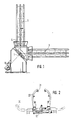
- a bundle collecting station is shown using the example of a twin collecting mandrel arrangement, in which two collecting mandrels 3 are mounted on a tilting mandrel base 1 in such a way that they can be brought into a loading position and an unloading position by means of a swivel drive 16.
- Each collecting mandrel 3 consists of a plurality of mandrel bars 4.
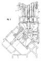
- Fig. 2 shows the top view of a limiting basket which is composed of two basket halves 20 which are held in the loading position in the closed position in solid lines, while in the unloading position, as indicated by dashed lines, are brought into the open position.
- a movement mechanism 22 is used which, as can be seen, can pivot the two basket halves 20 from the closed to the open position and vice versa.
- rollers or rods 21 are attached, which allow minimal contact with the coiled wire.
- the pivotable collecting mandrel shown in these figures is characterized by a plurality of mandrel rods 4, 5, of which the mandrel rods 4 are fixed mandrel rods while the mandrel rods 5 move in the manner to be described below are arranged.
- Fig. 3 shows in particular how the collecting mandrel 3 is mounted on and on the tilting mandrel base 1, which is designed in a manner known per se so that it can alternately pivot a twin-mandrel arrangement by means of the pivot drive 16 into its unloading or loading positions in the Location is.
- the design of the swivel head 2 is not the subject of the present application, so that a detailed description of the same can be omitted here.
- a conical pinion 10 is provided within the tilting mandrel base 1 and centrally mounted therein, which is in operative connection with the swivel drive 16.
- the teeth on the peripheral surface of the bevel pinion 10 engage the teeth of a bevel gear 11, which in turn is firmly connected to the central end of a central control shaft 8 of the mandrel 3.
- the control shaft 8 is seated in the region of the swivel head 2 or in a flange connection 23, such a flange connection being provided equally for the collection mandrel arrangement pointing upwards in FIG. 3 and for the vertical collection mandrel which is only indicated.
- the two flange connections 23 of the twin mandrel arrangement are connected to one another via a bevel gear 12, as can be seen in FIG. 3, the diameter of the two bevel gears of the bevel gear 12 being the same, so that a 1: 1 ratio results.
- the formation of the collecting mandrel 3 which is shown in Fig. 3 only in its lower part in section and 4 is continued, is characterized essentially by the central control shaft 8, fixed mandrel rods 4 and the movable mandrel rods 5.
- the fixed mandrel rods 4 are, as shown in FIG is executed.
- rockers 6 are held in three levels, at a distance from one another in height, on the free pivotable end of which the movable mandrel rods 5 are arranged (cf. also FIGS. 5 and 6).
- four movable mandrel bars 5 are arranged between four fixed mandrel bars 4.
- the fixed mandrel rods 4 are rigidly connected to one another by means of stiffening ribs 14, such stiffening ribs being able to be provided both between the respectively adjacent mandrel rods 4 and via the central control shaft 8.
- the design of the swing arms, levers and joints is such that self-lubricating sintered plain bearings are used so that additional lubrication with additional service is not necessary.
Landscapes
- Engineering & Computer Science (AREA)
- Mechanical Engineering (AREA)
- Winding, Rewinding, Material Storage Devices (AREA)
- Coiling Of Filamentary Materials In General (AREA)
- Wire Processing (AREA)
Applications Claiming Priority (2)
| Application Number | Priority Date | Filing Date | Title |
|---|---|---|---|
| DE3737418A DE3737418C1 (de) | 1987-11-04 | 1987-11-04 | Bundsammelstation fuer Drahtwalzstrassen |
| DE3737418 | 1987-11-04 |
Publications (2)
| Publication Number | Publication Date |
|---|---|
| EP0315032A2 true EP0315032A2 (fr) | 1989-05-10 |
| EP0315032A3 EP0315032A3 (fr) | 1989-11-23 |
Family
ID=6339759
Family Applications (1)
| Application Number | Title | Priority Date | Filing Date |
|---|---|---|---|
| EP88117781A Ceased EP0315032A3 (fr) | 1987-11-04 | 1988-10-25 | Poste de bobinage pour trains de laminage de fils |
Country Status (3)
| Country | Link |
|---|---|
| US (1) | US4913370A (fr) |
| EP (1) | EP0315032A3 (fr) |
| DE (1) | DE3737418C1 (fr) |
Cited By (1)
| Publication number | Priority date | Publication date | Assignee | Title |
|---|---|---|---|---|
| CN105562439A (zh) * | 2016-02-18 | 2016-05-11 | 内蒙古包钢钢联股份有限公司 | 一种高速线材集卷区域双芯棒干扰误差控制方法 |
Families Citing this family (3)
| Publication number | Priority date | Publication date | Assignee | Title |
|---|---|---|---|---|
| DE102004016658A1 (de) * | 2004-04-05 | 2005-10-27 | Böhnisch, Rudolf | Abrollvorrichtung für Ringbunde |
| US9162269B2 (en) * | 2012-11-29 | 2015-10-20 | Primetals Technologies USA LLC | Coil forming apparatus and method |
| CN115069819B (zh) * | 2022-08-18 | 2022-11-01 | 常州市武进大众标准件有限公司 | 一种螺丝卷材粗拔用的卷材安置架 |
Family Cites Families (7)
| Publication number | Priority date | Publication date | Assignee | Title |
|---|---|---|---|---|
| US1428119A (en) * | 1921-10-11 | 1922-09-05 | Charles E Rogers | Yarn reel |
| US1905178A (en) * | 1930-09-13 | 1933-04-25 | United Eng Foundry Co | Collapsible reel |
| US2457786A (en) * | 1945-12-22 | 1948-12-28 | Owens Corning Fiberglass Corp | Apparatus for winding strands |
| US2628040A (en) * | 1951-04-09 | 1953-02-10 | Western Electric Co | Apparatus for handling coils of strand material |
| US2983465A (en) * | 1957-02-18 | 1961-05-09 | Mc Graw Edison Co | Wire reel |
| DE2934439C2 (de) * | 1979-08-25 | 1986-12-18 | PHB Weserhütte AG, 5000 Köln | Vorrichtung zur Aufnahme und zum Abtransport von in einer Bundbildekammer gebildeten Drahtbunden |
| DE3525089C2 (de) * | 1985-07-13 | 1995-09-28 | Schloemann Siemag Ag | Drahtbund-Bildestation |
-
1987
- 1987-11-04 DE DE3737418A patent/DE3737418C1/de not_active Expired
-
1988
- 1988-10-25 EP EP88117781A patent/EP0315032A3/fr not_active Ceased
- 1988-11-02 US US07/265,912 patent/US4913370A/en not_active Expired - Fee Related
Cited By (1)
| Publication number | Priority date | Publication date | Assignee | Title |
|---|---|---|---|---|
| CN105562439A (zh) * | 2016-02-18 | 2016-05-11 | 内蒙古包钢钢联股份有限公司 | 一种高速线材集卷区域双芯棒干扰误差控制方法 |
Also Published As
| Publication number | Publication date |
|---|---|
| DE3737418C1 (de) | 1988-09-15 |
| EP0315032A3 (fr) | 1989-11-23 |
| US4913370A (en) | 1990-04-03 |
Similar Documents
| Publication | Publication Date | Title |
|---|---|---|
| EP2516081B1 (fr) | Support pour bobine métallique et dispositifs équipés d'un tel support | |
| DE3215245A1 (de) | Verfahren und vorrichtung zum verpacken von bandstahlrollen | |
| DE2840773A1 (de) | Halte- und fuehrungskorb fuer den dorn von kontinuierlichen walzwerken mit gehaltenem dorn | |
| DE2757202C2 (fr) | ||
| DE4139824C1 (fr) | ||
| DE2041179C3 (de) | Vorrichtung zum Sammeln von Drahtwindungen zu einem Bund in einer kontinuierlichen Drahtstraße | |
| DE3328516C1 (de) | Doppeltragwalzen-Wickelmaschine | |
| EP0315032A2 (fr) | Poste de bobinage pour trains de laminage de fils | |
| DE2141972A1 (de) | Vorrichtung zum unterteilen eines drahtwindungsstranges in einer bundbildestation | |
| DE4039048C2 (de) | Wickelvorrichtung zum Aufwickeln einer kontinuierlich zugeführten Kunststoffbahn | |
| DE2418316C2 (de) | Wickelmaschine für Blechbänder | |
| DE3311190A1 (de) | Verfahren und vorrichtung zum kontinuierlichen zerschneiden von band- oder strangfoermigem gut | |
| DE3825273A1 (de) | Spulentransporteinrichtung mit auskragendem dorn | |
| DE1527822B2 (de) | Vorrichtung zum Hersteller· von Walzdrahtbunden beliebigen Gewichtes aus horizontal herangeführten, einander überlappenden Drahtschlingen | |
| DE2150419C3 (de) | Vorrichtung zum Trennen eines Drahtwindungsstranges in einer Bundbildestation | |
| DE2212944C3 (de) | Verfahren und Vorrichtung zur Bildung von Walzdrahtbunden | |
| DE3109110C2 (de) | Vorrichtung zur Bildung von Walzdrahtbunden | |
| DE3634736C2 (de) | Maschine zur Herstellung rohrförmiger Bewehrungskörper für Betonrohre | |
| DE1142332B (de) | Haspel mit durch Staebe gebildetem drehbarem Wickelkorb zum wahlweisen Aufwickeln von Draht und Band | |
| DE2410769C3 (de) | Vorrichtung zum Stapeln von Bandoder Drahtbunden | |
| EP0227674B1 (fr) | Procede et dispositif pour le bobinage helicoidal de bandes | |
| DE10392460T5 (de) | Ringspulen-Wickelmaschine | |
| DE1235100B (de) | Vorrichtung zum Sammeln und Unterteilen von Drahtwindungen oder Gruppen derselben | |
| EP3521226B1 (fr) | Dispositif et procédé de formation d'une bobine de bande en plusieurs pièces | |
| DE2754716C2 (de) | Vorrichtung zur Herstellung von Kugelbehältern aus Blechteilen in Form von Kugelzweiecken |
Legal Events
| Date | Code | Title | Description |
|---|---|---|---|
| PUAI | Public reference made under article 153(3) epc to a published international application that has entered the european phase |
Free format text: ORIGINAL CODE: 0009012 |
|
| AK | Designated contracting states |
Kind code of ref document: A2 Designated state(s): DE GB IT LU SE |
|
| PUAL | Search report despatched |
Free format text: ORIGINAL CODE: 0009013 |
|
| AK | Designated contracting states |
Kind code of ref document: A3 Designated state(s): DE GB IT LU SE |
|
| 17P | Request for examination filed |
Effective date: 19891222 |
|
| 17Q | First examination report despatched |
Effective date: 19910705 |
|
| STAA | Information on the status of an ep patent application or granted ep patent |
Free format text: STATUS: THE APPLICATION HAS BEEN REFUSED |
|
| 18R | Application refused |
Effective date: 19920102 |