EP0315091A2 - Déflecteurs dans un réservoir d'encre d'une machine à rotative - Google Patents
Déflecteurs dans un réservoir d'encre d'une machine à rotative Download PDFInfo
- Publication number
- EP0315091A2 EP0315091A2 EP88118056A EP88118056A EP0315091A2 EP 0315091 A2 EP0315091 A2 EP 0315091A2 EP 88118056 A EP88118056 A EP 88118056A EP 88118056 A EP88118056 A EP 88118056A EP 0315091 A2 EP0315091 A2 EP 0315091A2
- Authority
- EP
- European Patent Office
- Prior art keywords
- ink
- profile body
- anilox roller
- application bar
- rotary printing
- Prior art date
- Legal status (The legal status is an assumption and is not a legal conclusion. Google has not performed a legal analysis and makes no representation as to the accuracy of the status listed.)
- Granted
Links
- 238000007774 anilox coating Methods 0.000 claims abstract description 31
- 238000011010 flushing procedure Methods 0.000 claims abstract description 8
- 239000003973 paint Substances 0.000 claims description 9
- 230000009969 flowable effect Effects 0.000 claims 1
- 230000002093 peripheral effect Effects 0.000 description 7
- 239000007788 liquid Substances 0.000 description 1
- 230000001105 regulatory effect Effects 0.000 description 1
Images



Classifications
-
- B—PERFORMING OPERATIONS; TRANSPORTING
- B41—PRINTING; LINING MACHINES; TYPEWRITERS; STAMPS
- B41F—PRINTING MACHINES OR PRESSES
- B41F31/00—Inking arrangements or devices
- B41F31/02—Ducts, containers, supply or metering devices
- B41F31/027—Ink rail devices for inking ink rollers
-
- B—PERFORMING OPERATIONS; TRANSPORTING
- B41—PRINTING; LINING MACHINES; TYPEWRITERS; STAMPS
- B41F—PRINTING MACHINES OR PRESSES
- B41F31/00—Inking arrangements or devices
- B41F31/02—Ducts, containers, supply or metering devices
- B41F31/03—Ink agitators
Definitions
- the invention relates to an ink application bar for a rinse inking unit of a rotary printing press according to the preamble of claim 1.
- DE-OS 31 35 711 shows a flushing inking unit for a rotary printing press.
- the flushing inking unit consists of an ink application bar and two doctor blades arranged above and below it, which together with an anilox roller form an ink distribution channel.
- the cross section of this ink distribution channel is rectangular and each has an additional edge in the area of the doctor blade.
- the US-PS 41 58 333 shows a flushing inking unit, which is also employed on an anilox roller having cups.
- the flushing inking unit has a doctor blade arranged underneath and a number of vertical walls which are provided with openings.
- a disadvantage of the one shown by the US-PS 41 58 333 The device is the suitability of the flushing inking unit for only one direction of rotation of the anilox roller.
- the ink flow through stationary walls and openings does nothing to change the pressure of the ink on the anilox roller.
- there is an extraordinarily large space requirement for the flushing inking unit which is many times larger than in the case of a conventional ink application bar.
- the invention has for its object to provide an ink application bar for a rinse inking unit of a rotary printing press, which favors the flow of ink in the ink chamber.
- the advantages of the invention are, in particular, that by building up a uniform ink flow without turbulence, even ink contact with the inking roller is possible even at high peripheral speeds, and ink liquid pressure can be regulated to better fill the cells of the inking roller.
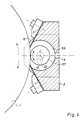
- a inking roller designed as anilox roller 1 is rotatably mounted in inking units (not shown).
- the anilox roller 1 forms, with an ink application bar 2 arranged parallel to its axis of rotation, an upper doctor blade 3 and a lower doctor blade 4, a roller-long ink distribution chamber 6.
- the ink distribution chamber 6 has smooth, rounded inner walls 7. In the middle of the ink distribution chamber 6 there is a hole 9 for the ink supply, which can be connected to an ink supply device, not shown.
- the paint knife 3 is screwed from the outside to an upper slope 11, the doctor blade 4 from the outside to a lower slope 12 of the paint application bar 2.
- the color distribution chamber 6 is covered on its end faces by means of side plates 14, 15 which, for. T.
- a profile body 16 is pivotally mounted in side plates 23, 28 by means of shaft journals 19, 21 attached to its end faces 17, 18.
- the side plates 23, 28 are each screwed to the side of the paint application bar 2, so that the side plates 14, 15 each between the paint application bar 2 and the side plates 23; 28 are arranged.
- the profile body 16 is almost as long as a width b of the anilox roller 1.
- the profile body 16 is elliptical in cross section.
- a pivoting of the profile body 16 about its axis of rotation 22 thus results in a change in the smallest gap width S O.
- the gap S is formed by the anilox roller 1 and the lateral surface 24 of the profile body 16 facing the anilox roller 1.
- a force F of the ink in the gap S is greatest just before the smallest gap width S O , as seen in the direction of rotation of the anilox roller 1.
- the load capacity f / b of the printing ink and thus the force of the ink on the cups 28 of the anilox roller 1 can be calculated using the following formula: (see also VDI research booklet 391, pages 82 - 85)
- ⁇ toughness of the color
- r1 radius of the anilox roller 1
- r2 radius of the outer surface 24 facing the anilox roller 1
- v1 peripheral speed of the anilox roller 1
- b length of the profile body 16.
- a change in the smallest gap width S o thus has an immediate change in the force of the color on the Anilox roller 1 result.
- the profile body 16 is pivoted by adjusting devices 31, 32 attached to the outside of the side plates 23, 28 in each case.
- the adjusting devices 31, 32 each consist of an adjusting spindle 33, 34 which is passed through a threaded through hole 38; 39 one on the side plate 23; 28 attached bracket 36; 37 is screwed through.
- At each end 41; 42 has the adjusting spindle 33; 34 a ball 43; 44, which in a vertical guide groove 46; 47 a lever 48; 49 engages.
- the lever 48; 49 is on the through the side plate 14; 15 and the side plate 23; 28 protruding shaft journal 19; 21 rotatably arranged.
- the adjusting spindle 33; 34 has an adjusting head 51; 52 on the z. B. can be knurled so that it is easy to use by hand. Of course, it is also possible to arrange a servomotor there for the purpose of remote adjustment.
- the profile body 16 is by means of the adjusting devices 31, 32 from a central position shown in dashed lines in FIG. 2, depending on the direction of rotation of the anilox roller 1 and the required force F of the ink on the anilox roller 1 by an angle ⁇ z. B. can be swung out ⁇ 20 °.
- FIG. 1 shows with a solid line a pivoting position of the profile body 16 for an anilox roller rotation direction in the clockwise direction.
- the dash-dotted line indicates a possible position of the profile body 16 for a direction of rotation of the anilox roller 1 counterclockwise.
- profile bodies 53, 54, 55
- 5 shows a cross section of the profile body 53 which has a convex shape on a side facing the anilox roller 1 and a concave shape on a color backflow side.
- the ends of the profile body 53 are rounded, one rounding having a larger radius than the other (wing profile).
- the profile body 54 in FIG. 6 essentially corresponds to the profile body 53, but with the same end radii.
- the profile body 56 in FIG. 7 has two concave outer surfaces.
- a cylindrical profile body 57 is arranged within a circular color distribution chamber 58.
- the profile body 57 is rotatably mounted in the side plates 23, 28 and is set against the anilox roller 1.
- the profile body 57 is driven by the anilox roller 1 by friction.
- means for example, mounting the profile body 57 in eccentric bushes) for changing the center distance of the profile body 57 and anilox roller 1, as a result of which there is greater slippage between the anilox roller 1 and the profile body 57.
Landscapes
- Inking, Control Or Cleaning Of Printing Machines (AREA)
- Rotary Presses (AREA)
- Inks, Pencil-Leads, Or Crayons (AREA)
Applications Claiming Priority (2)
| Application Number | Priority Date | Filing Date | Title |
|---|---|---|---|
| DE3737531 | 1987-11-05 | ||
| DE19873737531 DE3737531A1 (de) | 1987-11-05 | 1987-11-05 | Farbauftragsleiste fuer ein spuelfarbwerk einer rotationsdruckmaschine |
Publications (3)
| Publication Number | Publication Date |
|---|---|
| EP0315091A2 true EP0315091A2 (fr) | 1989-05-10 |
| EP0315091A3 EP0315091A3 (en) | 1989-08-16 |
| EP0315091B1 EP0315091B1 (fr) | 1993-01-13 |
Family
ID=6339823
Family Applications (1)
| Application Number | Title | Priority Date | Filing Date |
|---|---|---|---|
| EP88118056A Expired - Lifetime EP0315091B1 (fr) | 1987-11-05 | 1988-10-29 | Déflecteurs dans un réservoir d'encre d'une machine à rotative |
Country Status (5)
| Country | Link |
|---|---|
| US (1) | US4958561A (fr) |
| EP (1) | EP0315091B1 (fr) |
| JP (1) | JPH0741716B2 (fr) |
| DE (2) | DE3737531A1 (fr) |
| SU (1) | SU1625327A3 (fr) |
Cited By (9)
| Publication number | Priority date | Publication date | Assignee | Title |
|---|---|---|---|---|
| FR2676963A1 (fr) * | 1991-05-28 | 1992-12-04 | Koenig & Bauer Ag | Racle pour un groupe encreur de machine a imprimer rotative. |
| EP0663293A1 (fr) * | 1994-01-18 | 1995-07-19 | MAN Roland Druckmaschinen AG | Dispositif pour encrer un rouleau tramé |
| US5520110A (en) * | 1994-01-18 | 1996-05-28 | Man Roland Druckmaschinen Ag | Process and device for filling depressions, such as cups or channels, on the cylindrical surface of a rotating cylindrical body |
| US6655280B2 (en) | 2001-01-12 | 2003-12-02 | Heidelberger Druckmaschinen Ag | Inking unit in a printing machine having a chambered doctor blade and multiple inking zones |
| WO2008152050A1 (fr) * | 2007-06-11 | 2008-12-18 | Windmöller & Hölscher Kg | Racle de compartiment à encre dans un mécanisme d'encrage de presse rotative |
| US7995473B2 (en) | 2006-08-11 | 2011-08-09 | Velocix Ltd. | Content delivery system for digital object |
| US8010748B2 (en) | 2006-08-11 | 2011-08-30 | Velocix Ltd. | Cache structure for peer-to-peer distribution of digital objects |
| US8244867B2 (en) | 2006-08-11 | 2012-08-14 | Velocix Limited | System and method for the location of caches |
| US9241032B2 (en) | 2006-08-11 | 2016-01-19 | Alcatel Lucent | Storage performance |
Families Citing this family (18)
| Publication number | Priority date | Publication date | Assignee | Title |
|---|---|---|---|---|
| DE4001733A1 (de) * | 1990-01-22 | 1991-07-25 | Windmoeller & Hoelscher | Rakelvorrichtung fuer ein spuelfarbwerk einer rotationsdruckmaschine |
| DE4012825A1 (de) * | 1990-04-23 | 1991-10-24 | Koenig & Bauer Ag | Kammerrakel |
| DE4138807C1 (en) * | 1991-11-26 | 1993-06-03 | Cornelis Wapenveld Nl Gorter | Colour chamber doctor - is for colour-transfer, screened circular cylindrical body such as screen roller or engraved cylinder |
| DE4200837C2 (de) * | 1992-01-15 | 1993-11-04 | Koenig & Bauer Ag | Kammerrakel fuer ein kurzfarbwerk einer rotationsdruckmaschine |
| DE4401299C2 (de) * | 1994-01-18 | 1997-04-30 | Roland Man Druckmasch | Vorrichtung zum Einfärben einer Rasterwalze einer Rotationsdruckmaschine |
| DE4438262C2 (de) | 1994-10-26 | 1996-09-05 | Koenig & Bauer Albert Ag | Rakeleinrichtung für ein Kurzfarbwerk einer Rotationsdruckmaschine |
| DE19536268C1 (de) * | 1995-09-28 | 1997-02-06 | Windmoeller & Hoelscher | Rakelvorrichtung für ein Spülfarbwerk einer Rotationsdruckmaschine |
| DE19642399B4 (de) * | 1995-10-14 | 2004-04-15 | Techno Roll Co., Ltd., Izumi | Druckfarbenwannenanordnung für eine Druckerpresse |
| US5826509A (en) * | 1995-10-18 | 1998-10-27 | Deneka; P. Kenneth | Printing coating head device |
| DE19600651A1 (de) * | 1996-01-10 | 1997-07-17 | Polywest Kunststofftechnik | Farbkammerrakel für einen farbübertragenden Körper |
| FR2758493B1 (fr) * | 1997-01-17 | 1999-04-02 | Soc Et De Machines Pour Les Ar | Dispositif pour l'encrage d'un cylindre trame |
| NL1006861C2 (nl) * | 1997-08-27 | 1999-03-02 | Cornelis Gorter | Kamerrakelsysteem. |
| US6210757B1 (en) | 1998-03-23 | 2001-04-03 | Black Clawson Company, Inc. | Pressurized enclosed gravure applicator and method |
| GB9817194D0 (en) * | 1998-08-07 | 1998-10-07 | Hayneswood Engineering Sales L | Coating apparatus |
| ITMI20031539A1 (it) * | 2003-07-25 | 2003-10-24 | Percivalle Special Converting S A S Di Percivall | Unita' di inchiostrazione e raclatura per un gruppo di stampa e spalmatura rotocalcografica. |
| DE102006002170A1 (de) * | 2006-01-17 | 2007-07-26 | Heidelberger Druckmaschinen Ag | Druckmaschine |
| DE102007010528B4 (de) * | 2006-03-28 | 2017-10-19 | Heidelberger Druckmaschinen Ag | Druckmaschine und Verfahren zu deren Betrieb |
| CN101045366B (zh) | 2006-03-28 | 2011-01-12 | 海德堡印刷机械股份公司 | 用于运行印刷机的方法 |
Family Cites Families (17)
| Publication number | Priority date | Publication date | Assignee | Title |
|---|---|---|---|---|
| DE95770C (fr) * | ||||
| US1778600A (en) * | 1928-08-03 | 1930-10-14 | Richard E Jones | Method of and mechanism for agitating fluids and semifluids |
| DE1140587B (de) * | 1957-07-26 | 1962-12-06 | Harold W Gegenheimer | Ruehrvorrichtung fuer Farbkaesten von Druckmaschinen |
| US3044396A (en) * | 1959-01-02 | 1962-07-17 | Carl Allers Ets | Inking mechanism for intaglio printing machines |
| DE1621909A1 (de) * | 1966-07-01 | 1971-08-19 | Fuji Photo Film Co Ltd | Verfahren zum Aufbringen einer UEberzugsfluessigkeit auf die Oberflaeche einer sich kontinuierlich bewegenden Bahn |
| DE2155347C3 (de) * | 1970-12-29 | 1975-04-10 | Polygraph Leipzig | Vorrichtung zum Schwenken von Farbrührgeräten an Druckmaschinen |
| US4158333A (en) * | 1978-05-01 | 1979-06-19 | Anpa Research Institute | Inking baffle for rotary newspaper presses |
| DE3135711A1 (de) * | 1981-07-29 | 1983-02-10 | Windmöller & Hölscher, 4540 Lengerich | Spuelfarbwerk fuer eine rotationsdruckmaschine |
| DE110081T1 (de) * | 1982-12-02 | 1984-10-11 | Rockwell International Corp., Pittsburgh, Pa. | Farbverteilbalken. |
| DE3320638C2 (de) * | 1983-06-08 | 1986-10-16 | Koenig & Bauer AG, 8700 Würzburg | Farbabteileinrichtung an Farbkastenwalzen von Druckmaschinen |
| DE3338095A1 (de) * | 1983-10-20 | 1985-05-09 | J.M. Voith Gmbh, 7920 Heidenheim | Streicheinrichtung |
| CH663362A5 (de) * | 1984-01-07 | 1987-12-15 | Jagenberg Ag | Vorrichtung zum beschichten von ueber eine stuetzwalze laufenden materialbahnen mit regelbarer auftragsstaerke. |
| DE3438380A1 (de) * | 1984-10-19 | 1986-04-24 | J.M. Voith Gmbh, 7920 Heidenheim | Streicheinrichtung zur beschichtung laufender warenbahnen |
| DE3446757C2 (de) * | 1984-11-17 | 1995-05-24 | Voith Gmbh J M | Streicheinrichtung |
| DE3539759C1 (de) * | 1985-11-09 | 1987-04-02 | Roland Man Druckmasch | Farbteiler fuer ein Flexo-Farbwerk |
| DE3616645A1 (de) * | 1986-05-16 | 1987-11-19 | Voith Gmbh J M | Streicheinrichtung |
| DE3704433A1 (de) * | 1987-02-12 | 1988-08-25 | Frankenthal Ag Albert | Kurzfarbwerk |
-
1987
- 1987-11-05 DE DE19873737531 patent/DE3737531A1/de not_active Withdrawn
-
1988
- 1988-10-27 JP JP63269648A patent/JPH0741716B2/ja not_active Expired - Lifetime
- 1988-10-29 DE DE8888118056T patent/DE3877519D1/de not_active Expired - Fee Related
- 1988-10-29 EP EP88118056A patent/EP0315091B1/fr not_active Expired - Lifetime
- 1988-11-01 US US07/265,568 patent/US4958561A/en not_active Expired - Lifetime
- 1988-11-04 SU SU884356800A patent/SU1625327A3/ru active
Cited By (10)
| Publication number | Priority date | Publication date | Assignee | Title |
|---|---|---|---|---|
| FR2676963A1 (fr) * | 1991-05-28 | 1992-12-04 | Koenig & Bauer Ag | Racle pour un groupe encreur de machine a imprimer rotative. |
| EP0663293A1 (fr) * | 1994-01-18 | 1995-07-19 | MAN Roland Druckmaschinen AG | Dispositif pour encrer un rouleau tramé |
| US5520110A (en) * | 1994-01-18 | 1996-05-28 | Man Roland Druckmaschinen Ag | Process and device for filling depressions, such as cups or channels, on the cylindrical surface of a rotating cylindrical body |
| US5560294A (en) * | 1994-01-18 | 1996-10-01 | Man Roland Druckmaschinen Ag | Device for inking a screen roller |
| US6655280B2 (en) | 2001-01-12 | 2003-12-02 | Heidelberger Druckmaschinen Ag | Inking unit in a printing machine having a chambered doctor blade and multiple inking zones |
| US7995473B2 (en) | 2006-08-11 | 2011-08-09 | Velocix Ltd. | Content delivery system for digital object |
| US8010748B2 (en) | 2006-08-11 | 2011-08-30 | Velocix Ltd. | Cache structure for peer-to-peer distribution of digital objects |
| US8244867B2 (en) | 2006-08-11 | 2012-08-14 | Velocix Limited | System and method for the location of caches |
| US9241032B2 (en) | 2006-08-11 | 2016-01-19 | Alcatel Lucent | Storage performance |
| WO2008152050A1 (fr) * | 2007-06-11 | 2008-12-18 | Windmöller & Hölscher Kg | Racle de compartiment à encre dans un mécanisme d'encrage de presse rotative |
Also Published As
| Publication number | Publication date |
|---|---|
| EP0315091A3 (en) | 1989-08-16 |
| SU1625327A3 (ru) | 1991-01-30 |
| DE3737531A1 (de) | 1989-05-18 |
| JPH0741716B2 (ja) | 1995-05-10 |
| US4958561A (en) | 1990-09-25 |
| JPH01154760A (ja) | 1989-06-16 |
| DE3877519D1 (de) | 1993-02-25 |
| EP0315091B1 (fr) | 1993-01-13 |
Similar Documents
| Publication | Publication Date | Title |
|---|---|---|
| EP0315091B1 (fr) | Déflecteurs dans un réservoir d'encre d'une machine à rotative | |
| EP0350839A2 (fr) | Système d'encrage pour encres d'impression dans des groupes d'impression rotatifs | |
| DE2054678B2 (de) | Feuchtwerk fuer lithographische druckmschinen | |
| EP0019073B1 (fr) | Dispositif d'encrage pour machine à imprimer | |
| EP0324140B1 (fr) | Dispositif d'encrage | |
| DE2130278A1 (de) | Mehrzweck-seitenrahmen fuer rotationsdruckmaschinen | |
| DE3731768C1 (de) | Feuchtwerk fuer Rotations-Offsetdruckmaschinen | |
| DE2814889B2 (de) | Vorrichtung zur fernsteuerbaren Einstellung zonenbreiter Dosierelemente eines Farbkastens | |
| EP0145904A2 (fr) | Dispositif de dosage de l'agent mouillant dans le système de mouillage d'une machine d'impression | |
| DE2849096C2 (de) | Feuchtwerk | |
| DE4403256C2 (de) | Druckmaschine mit einer Stellvorrichtung zum Drucken-/Druckabstellen von Druckwerkszylindern und zum Einstellen des Ausstelldrucks | |
| DD203016A1 (de) | Farbwerk fuer druckmaschinen | |
| EP1603750B1 (fr) | Groupe d'impression d'une unite d'impression possedant au moins deux groupes d'impression situes verticalement l'un au-dessus de l'autre dans une presse, et unite d'impression | |
| EP0115301A2 (fr) | Encrier pour encre courte | |
| DD203868A1 (de) | Vorrichtung zum druckan- und abstellen von zylindern | |
| DE3938447C2 (fr) | ||
| EP0144687A2 (fr) | Dispositif de dosage de l'encre dans le système d'encrage d'une machine à imprimer | |
| DE4103742C2 (de) | Einstellbare Feuchtwerks- oder Farbwerkswalze | |
| DE3407428C1 (de) | Anordnung zum Antrieb einer Walze oder eines Zylinders einer von Buchdruck auf Flexodruck umruestbaren Rotationsdruckmaschine | |
| DE3446675C2 (de) | Bürsten-Feuchtwerk für Rotations-Offsetdruckmaschinen | |
| DE3308991C2 (fr) | ||
| EP0387485A2 (fr) | Dispositif pour changer de position le deuxième rouleau (supérieur) d'une paire de rouleaux intermédiaires de raccordement entre les groupes d'encrage et de mouillage | |
| DE2846701C2 (fr) | ||
| DE1915280A1 (de) | Einrichtung fuer das Einstellen der Auftragwalze in einem Farbwerk | |
| DE2324684B2 (de) | Färb- oder Feuchtwerksantrieb für Rotationsdruckmaschinen |
Legal Events
| Date | Code | Title | Description |
|---|---|---|---|
| PUAI | Public reference made under article 153(3) epc to a published international application that has entered the european phase |
Free format text: ORIGINAL CODE: 0009012 |
|
| AK | Designated contracting states |
Kind code of ref document: A2 Designated state(s): CH DE FR GB IT LI SE |
|
| PUAL | Search report despatched |
Free format text: ORIGINAL CODE: 0009013 |
|
| AK | Designated contracting states |
Kind code of ref document: A3 Designated state(s): CH DE FR GB IT LI SE |
|
| 17P | Request for examination filed |
Effective date: 19891207 |
|
| 17Q | First examination report despatched |
Effective date: 19910328 |
|
| ITF | It: translation for a ep patent filed | ||
| GRAA | (expected) grant |
Free format text: ORIGINAL CODE: 0009210 |
|
| AK | Designated contracting states |
Kind code of ref document: B1 Designated state(s): CH DE FR GB IT LI SE |
|
| REF | Corresponds to: |
Ref document number: 3877519 Country of ref document: DE Date of ref document: 19930225 |
|
| ET | Fr: translation filed | ||
| GBT | Gb: translation of ep patent filed (gb section 77(6)(a)/1977) |
Effective date: 19930128 |
|
| PLBE | No opposition filed within time limit |
Free format text: ORIGINAL CODE: 0009261 |
|
| STAA | Information on the status of an ep patent application or granted ep patent |
Free format text: STATUS: NO OPPOSITION FILED WITHIN TIME LIMIT |
|
| 26N | No opposition filed | ||
| EAL | Se: european patent in force in sweden |
Ref document number: 88118056.6 |
|
| PGFP | Annual fee paid to national office [announced via postgrant information from national office to epo] |
Ref country code: GB Payment date: 20001010 Year of fee payment: 13 |
|
| PGFP | Annual fee paid to national office [announced via postgrant information from national office to epo] |
Ref country code: FR Payment date: 20001017 Year of fee payment: 13 |
|
| PGFP | Annual fee paid to national office [announced via postgrant information from national office to epo] |
Ref country code: SE Payment date: 20001023 Year of fee payment: 13 |
|
| PGFP | Annual fee paid to national office [announced via postgrant information from national office to epo] |
Ref country code: CH Payment date: 20001030 Year of fee payment: 13 |
|
| PG25 | Lapsed in a contracting state [announced via postgrant information from national office to epo] |
Ref country code: GB Free format text: LAPSE BECAUSE OF NON-PAYMENT OF DUE FEES Effective date: 20011029 |
|
| PG25 | Lapsed in a contracting state [announced via postgrant information from national office to epo] |
Ref country code: SE Free format text: LAPSE BECAUSE OF NON-PAYMENT OF DUE FEES Effective date: 20011030 |
|
| PG25 | Lapsed in a contracting state [announced via postgrant information from national office to epo] |
Ref country code: LI Free format text: LAPSE BECAUSE OF NON-PAYMENT OF DUE FEES Effective date: 20011031 Ref country code: CH Free format text: LAPSE BECAUSE OF NON-PAYMENT OF DUE FEES Effective date: 20011031 |
|
| REG | Reference to a national code |
Ref country code: GB Ref legal event code: IF02 |
|
| EUG | Se: european patent has lapsed |
Ref document number: 88118056.6 |
|
| REG | Reference to a national code |
Ref country code: CH Ref legal event code: PL |
|
| GBPC | Gb: european patent ceased through non-payment of renewal fee |
Effective date: 20011029 |
|
| PG25 | Lapsed in a contracting state [announced via postgrant information from national office to epo] |
Ref country code: FR Free format text: LAPSE BECAUSE OF NON-PAYMENT OF DUE FEES Effective date: 20020628 |
|
| REG | Reference to a national code |
Ref country code: FR Ref legal event code: ST |
|
| PGFP | Annual fee paid to national office [announced via postgrant information from national office to epo] |
Ref country code: DE Payment date: 20031210 Year of fee payment: 16 |
|
| PG25 | Lapsed in a contracting state [announced via postgrant information from national office to epo] |
Ref country code: DE Free format text: LAPSE BECAUSE OF NON-PAYMENT OF DUE FEES Effective date: 20050503 |
|
| PG25 | Lapsed in a contracting state [announced via postgrant information from national office to epo] |
Ref country code: IT Free format text: LAPSE BECAUSE OF NON-PAYMENT OF DUE FEES;WARNING: LAPSES OF ITALIAN PATENTS WITH EFFECTIVE DATE BEFORE 2007 MAY HAVE OCCURRED AT ANY TIME BEFORE 2007. THE CORRECT EFFECTIVE DATE MAY BE DIFFERENT FROM THE ONE RECORDED. Effective date: 20051029 |