EP0315225A1 - Verfahren zum Verbrennen eines schwefelwasserstoffhaltigen Gases - Google Patents
Verfahren zum Verbrennen eines schwefelwasserstoffhaltigen Gases Download PDFInfo
- Publication number
- EP0315225A1 EP0315225A1 EP88201637A EP88201637A EP0315225A1 EP 0315225 A1 EP0315225 A1 EP 0315225A1 EP 88201637 A EP88201637 A EP 88201637A EP 88201637 A EP88201637 A EP 88201637A EP 0315225 A1 EP0315225 A1 EP 0315225A1
- Authority
- EP
- European Patent Office
- Prior art keywords
- burner
- gas
- combustion chamber
- oxygen
- gas mixture
- Prior art date
- Legal status (The legal status is an assumption and is not a legal conclusion. Google has not performed a legal analysis and makes no representation as to the accuracy of the status listed.)
- Granted
Links
- 239000007789 gas Substances 0.000 title claims abstract description 63
- 238000000034 method Methods 0.000 title claims abstract description 16
- RWSOTUBLDIXVET-UHFFFAOYSA-N Dihydrogen sulfide Chemical compound S RWSOTUBLDIXVET-UHFFFAOYSA-N 0.000 title 1
- 229910000037 hydrogen sulfide Inorganic materials 0.000 title 1
- 239000000203 mixture Substances 0.000 claims abstract description 28
- 238000002485 combustion reaction Methods 0.000 claims abstract description 23
- 229910052760 oxygen Inorganic materials 0.000 claims abstract description 17
- 239000001301 oxygen Substances 0.000 claims abstract description 17
- QVGXLLKOCUKJST-UHFFFAOYSA-N atomic oxygen Chemical compound [O] QVGXLLKOCUKJST-UHFFFAOYSA-N 0.000 claims abstract description 16
- NINIDFKCEFEMDL-UHFFFAOYSA-N Sulfur Chemical compound [S] NINIDFKCEFEMDL-UHFFFAOYSA-N 0.000 claims abstract description 13
- 229910002091 carbon monoxide Inorganic materials 0.000 claims abstract description 6
- 229930195733 hydrocarbon Natural products 0.000 claims abstract description 5
- 150000002430 hydrocarbons Chemical class 0.000 claims abstract description 5
- 239000004215 Carbon black (E152) Substances 0.000 claims abstract 2
- 230000007062 hydrolysis Effects 0.000 claims description 6
- 238000006460 hydrolysis reaction Methods 0.000 claims description 6
- 238000006243 chemical reaction Methods 0.000 claims description 5
- 239000005864 Sulphur Substances 0.000 abstract 1
- CURLTUGMZLYLDI-UHFFFAOYSA-N Carbon dioxide Chemical compound O=C=O CURLTUGMZLYLDI-UHFFFAOYSA-N 0.000 description 16
- 229910002092 carbon dioxide Inorganic materials 0.000 description 8
- 229910052739 hydrogen Inorganic materials 0.000 description 7
- 239000001257 hydrogen Substances 0.000 description 7
- UFHFLCQGNIYNRP-UHFFFAOYSA-N Hydrogen Chemical compound [H][H] UFHFLCQGNIYNRP-UHFFFAOYSA-N 0.000 description 6
- 239000003054 catalyst Substances 0.000 description 6
- 238000005984 hydrogenation reaction Methods 0.000 description 5
- GWEVSGVZZGPLCZ-UHFFFAOYSA-N Titan oxide Chemical compound O=[Ti]=O GWEVSGVZZGPLCZ-UHFFFAOYSA-N 0.000 description 4
- PNEYBMLMFCGWSK-UHFFFAOYSA-N aluminium oxide Inorganic materials [O-2].[O-2].[O-2].[Al+3].[Al+3] PNEYBMLMFCGWSK-UHFFFAOYSA-N 0.000 description 4
- 229910052593 corundum Inorganic materials 0.000 description 4
- 229910001845 yogo sapphire Inorganic materials 0.000 description 4
- XLYOFNOQVPJJNP-UHFFFAOYSA-N water Substances O XLYOFNOQVPJJNP-UHFFFAOYSA-N 0.000 description 3
- UGFAIRIUMAVXCW-UHFFFAOYSA-N Carbon monoxide Chemical compound [O+]#[C-] UGFAIRIUMAVXCW-UHFFFAOYSA-N 0.000 description 2
- 238000006555 catalytic reaction Methods 0.000 description 2
- 238000010304 firing Methods 0.000 description 2
- 238000000926 separation method Methods 0.000 description 2
- 150000003464 sulfur compounds Chemical class 0.000 description 2
- 241001156002 Anthonomus pomorum Species 0.000 description 1
- MYMOFIZGZYHOMD-UHFFFAOYSA-N Dioxygen Chemical compound O=O MYMOFIZGZYHOMD-UHFFFAOYSA-N 0.000 description 1
- 238000006887 Ullmann reaction Methods 0.000 description 1
- 238000010521 absorption reaction Methods 0.000 description 1
- 230000015572 biosynthetic process Effects 0.000 description 1
- 239000001569 carbon dioxide Substances 0.000 description 1
- 230000003197 catalytic effect Effects 0.000 description 1
- 238000001816 cooling Methods 0.000 description 1
- 238000010586 diagram Methods 0.000 description 1
- 239000000446 fuel Substances 0.000 description 1
- 238000010438 heat treatment Methods 0.000 description 1
- 230000000887 hydrating effect Effects 0.000 description 1
- 150000002431 hydrogen Chemical class 0.000 description 1
- 230000003301 hydrolyzing effect Effects 0.000 description 1
- 238000005470 impregnation Methods 0.000 description 1
- DOTMOQHOJINYBL-UHFFFAOYSA-N molecular nitrogen;molecular oxygen Chemical compound N#N.O=O DOTMOQHOJINYBL-UHFFFAOYSA-N 0.000 description 1
- 239000003209 petroleum derivative Substances 0.000 description 1
- 239000000126 substance Substances 0.000 description 1
- 229910052717 sulfur Inorganic materials 0.000 description 1
- 239000011593 sulfur Substances 0.000 description 1
- 238000003786 synthesis reaction Methods 0.000 description 1
- 238000005979 thermal decomposition reaction Methods 0.000 description 1
Images
Classifications
-
- C—CHEMISTRY; METALLURGY
- C01—INORGANIC CHEMISTRY
- C01B—NON-METALLIC ELEMENTS; COMPOUNDS THEREOF; METALLOIDS OR COMPOUNDS THEREOF NOT COVERED BY SUBCLASS C01C
- C01B17/00—Sulfur; Compounds thereof
- C01B17/02—Preparation of sulfur; Purification
- C01B17/04—Preparation of sulfur; Purification from gaseous sulfur compounds including gaseous sulfides
- C01B17/0404—Preparation of sulfur; Purification from gaseous sulfur compounds including gaseous sulfides by processes comprising a dry catalytic conversion of hydrogen sulfide-containing gases, e.g. the Claus process
- C01B17/0413—Preparation of sulfur; Purification from gaseous sulfur compounds including gaseous sulfides by processes comprising a dry catalytic conversion of hydrogen sulfide-containing gases, e.g. the Claus process characterised by the combustion step
- C01B17/0417—Combustion reactors
-
- C—CHEMISTRY; METALLURGY
- C01—INORGANIC CHEMISTRY
- C01B—NON-METALLIC ELEMENTS; COMPOUNDS THEREOF; METALLOIDS OR COMPOUNDS THEREOF NOT COVERED BY SUBCLASS C01C
- C01B17/00—Sulfur; Compounds thereof
- C01B17/48—Sulfur dioxide; Sulfurous acid
- C01B17/50—Preparation of sulfur dioxide
- C01B17/508—Preparation of sulfur dioxide by oxidation of sulfur compounds
-
- F—MECHANICAL ENGINEERING; LIGHTING; HEATING; WEAPONS; BLASTING
- F23—COMBUSTION APPARATUS; COMBUSTION PROCESSES
- F23D—BURNERS
- F23D14/00—Burners for combustion of a gas, e.g. of a gas stored under pressure as a liquid
- F23D14/20—Non-premix gas burners, i.e. in which gaseous fuel is mixed with combustion air on arrival at the combustion zone
- F23D14/22—Non-premix gas burners, i.e. in which gaseous fuel is mixed with combustion air on arrival at the combustion zone with separate air and gas feed ducts, e.g. with ducts running parallel or crossing each other
-
- F—MECHANICAL ENGINEERING; LIGHTING; HEATING; WEAPONS; BLASTING
- F23—COMBUSTION APPARATUS; COMBUSTION PROCESSES
- F23D—BURNERS
- F23D14/00—Burners for combustion of a gas, e.g. of a gas stored under pressure as a liquid
- F23D14/32—Burners for combustion of a gas, e.g. of a gas stored under pressure as a liquid using a mixture of gaseous fuel and pure oxygen or oxygen-enriched air
Definitions
- the invention relates to a method for burning an H2S-containing feed gas with oxygen and air in at least one burner, which opens into a combustion chamber, for producing a gas mixture containing H2S and SO2 for conversion into elemental sulfur according to the Claus method, wherein one passes through the central tube the burner oxygen, through at least one coaxially surrounding the central tube, the H2S-containing feed gas and through a coaxial outer tube, air is passed into the combustion chamber.
- German Patent 34 30 015. It works at relatively low temperatures and low flow rates of the gases in the mouth area of the burner.
- the invention has for its object to be able to process an H2S-containing feed gas which also contains hydrocarbons or CO2. This is done according to the invention in the method mentioned at the outset by giving the burner an H2S-containing feed gas, the content of hydrocarbons or CO2 of which is at least 5 vol.
- An expedient development of the method according to the invention is that the gas mixture is passed from the combustion chamber through a Claus zone and catalytic converts H2S and SO2 to elemental sulfur, that the exhaust gas from the Claus zone is treated in a hydrolysis zone and a gas mixture is drawn off, which consists predominantly of H2S , H2 and CO, from which one separates H2S.
- These further treatment stages can be carried out in a manner known per se. Details of these process steps are described in DE-OS 34 15 722 and in the corresponding US Pat. No. 4,632,819 and in Ullmanns Encyklopadie der Technische Chemie, 4th Edition (1982), Volume 21, pages 8-26.
- the combustion chamber (1) has a plurality of burners (2, 3) and an auxiliary firing (4) known per se.
- the burner (2) is fed through line (6) oxygen, through line (7) the feed gas and through line (8) air.
- the auxiliary firing (4) is fed through line (10) of gaseous fuel and through line (11) air.
- the mouth area of a burner consists of concentric tubes, which can be seen in Fig. 2.
- the oxygen flows through the narrowed central tube (13) and leaves the tube at flow velocities of 50 to 250 m / sec.
- the central tube (13) surrounds a second tube (14) through which the feed gas is passed into the combustion.
- the feed gas contains at least 5% by volume of hydrocarbons or CO2.
- the flow rate of the feed gas is 10 to 30 m / sec when leaving the second tube. Air is brought in through the outer tube (15).
- the burner arrangement as well as the gases and their flow velocities create a flame structure that favors the desired reactions.
- the temperatures are in the range from 2000 to 3000 ° C and preferably at least 2300 °, which favors the conversion of CO2 into CO and oxygen and the thermal decomposition of water.
- the air envelope (19) which surrounds the hot area of the flame, protects by its relative low temperatures the lining of the combustion chamber and counteracts the cooling of the core area (18) of the flame.
- the temperatures are approximately in the range from 800 to 1300 ° C. Temperatures of approximately 1350 to 1650 ° C. are established in the vicinity of the outlet (20) of the combustion chamber.
- the gas mixture at these temperatures has at least 2% by volume of carbon monoxide and at least 8% by volume of hydrogen. This gas mixture now also contains SO2, which is formed by burning part of the H2S.
- the gas mixture from the combustion chamber (1) through the line (21) to a Claus plant (22), where on catalysts at temperatures from initially about 320 to finally about 200 ° C H2S with SO2 to elemental sulfur in a known manner is implemented.
- the known catalysts are e.g. essentially of TiO2 and Al2O3, which are arranged in different fixed beds.
- the exhaust gas from the Claus plant passes in line (23) to a hydrolysis zone (24), in which the components present in the gas mixture are treated hydrolyzing and hydrating. Since the exhaust gas contains enough hydrogen, it is not necessary to introduce foreign hydrogen for this hydrogenation.
- the hydrolysis zone and the hydrogenation taking place in it at the same time the following should be explained: over a catalyst consisting, for example, of Al2O3 as a support and a Co and Mo impregnation, the remaining COS and CS2 are hydrolyzed to H2S with steam. At the same time, residual elemental sulfur and SO2 are hydrogenated to H2S with hydrogen.
- the hydrolysis and the hydrogenation are carried out on the same catalyst, which is arranged in a fixed bed, at temperatures of about 300 to 350 ° C.
- the treated gas now consists essentially of H2S, N2, CO and H2.
- This gas mixture is fed through line (25) to a separation system (26) in which one separates H2S, for example by chemical absorption, for example by means of methyldiethyleneamines (MDEA). Separated H2S leads in line (27) back to the combustion chamber (1), CO, H2 and N2 are available as a gas mixture for further use in line (28).
- MDEA methyldiethyleneamines
- a feed gas with the composition, calculated dry, H2S 86.0 vol.% CO 0.2 vol.% CH4 1.0 vol.% CO2 10.7 vol.% N2 2.0 vol.% H2 0.1 vol.% is fed to a combustion chamber with four burners.
- this feed gas is partially burned with different air-oxygen ratios.
- the technically pure oxygen used has a flow rate of 150 to 200 m / sec when it emerges from the respective burner, the flow rate of the feed gas at the burner mouth is 20 to 25 m / sec. As far as quantities are given in the following tables, they refer to 1000 Nm3 dry feed gas.
- the gas mixture leaving the combustion chamber (1) has the following composition (vol.%): A B C. H2S 8.3 9.5 9.9 SO2 4.8 5.5 5.7 H2O 41.0 46.6 48.6 COS 0.8 0.9 1.0 CS2 0.2 0.3 0.3 CO 3.5 4.5 4.8 CO2 3.6 3.8 3.9 H2 10.9 14.2 15.4 N2 25.0 13.0 8.6 other sulfur compounds 1.9 1.7 1.8 100.0 100.0 100.0 Amount of gas: without elemental sulfur (Nm3) 1436 1232 1172 with elemental sulfur (Nm3) 1761 1558 1498
- This gas mixture is subjected to a two-stage Claus gas catalysis, using TiO2 as catalysts in the first stage and Al2O3 in the second stage. Thereby 97% of the sulfur is recovered.
- the exhaust gas from the Claus gas catalysis is hydrogenated and hydrolyzed, the procedure being as follows: the gas mixture is heated to 320 ° C. and fed to a reactor in which the hydrogenation and hydrolysis are carried out over one and the same catalyst (Al2O3 impregnated with Co and Mo). In the gas mixture treated in this way, all sulfur compounds are only present as H2S; the water formed during the reactions is removed up to 4% by volume. The H2S is then removed from the gas mixture in a separation system using MDEA using the sulften process from Ford, Bacon and Davis Inc., Dallas (USA), down to about 10 ppm by volume and a residual gas is obtained in the line (28 ) with the following composition: A B C. H2 19.1 29.7 34.8 CO 6.9 10.5 12.2 CO2 8.9 11.1 12.2 N2 61.1 44.7 36.8 H2O 4.0 4.0 4.0 4.0 4.0 4.0
- This gas mixture in particular Examples B and C, can e.g. be used in the hydrodesulfurization of petroleum products or as heating gas.
Landscapes
- Chemical & Material Sciences (AREA)
- Engineering & Computer Science (AREA)
- Organic Chemistry (AREA)
- Combustion & Propulsion (AREA)
- Inorganic Chemistry (AREA)
- Mechanical Engineering (AREA)
- Chemical Kinetics & Catalysis (AREA)
- General Engineering & Computer Science (AREA)
- Treating Waste Gases (AREA)
- Incineration Of Waste (AREA)
- Catalysts (AREA)
- Exhaust Gas Treatment By Means Of Catalyst (AREA)
- Solid-Sorbent Or Filter-Aiding Compositions (AREA)
- Manufacture And Refinement Of Metals (AREA)
- Gas Separation By Absorption (AREA)
Abstract
Description
- Die Erfindung betrifft ein Verfahren zum Verbrennen eines H₂S-haltigen Einsatzgases mit Sauerstoff und Luft in mindestens einem Brenner, der in eine Brennkammer mündet, zum Erzeugen eines H₂S und SO₂ enthaltenden Gasgemisches zur Umwandlung in Elementarschwefel nach dem Claus-Verfahren, wobei man durch das Zentralrohr des Brenners Sauerstoff, durch mindestens ein das Zentralrohr koaxial umgebendes zweites Rohr das H₂S-haltige Einsatzgas und durch ein koaxiales äußeres Rohr Luft in die Brennkammer leitet.
- Ein solches Verfahren mit der zugehörigen Apparatur ist im deutschen Patent 34 30 015 beschrieben. Dabei arbeitet man bei relativ niedrigen Temperaturen und niedrigen Strömungsgeschwindigkeiten der Gase im Mündungsbereich des Brenners. Der Erfindung liegt die Aufgabe zugrunde, ein H₂S-haltiges Einsatzgas verarbeiten zu können, das auch Kohlenwasserstoffe oder CO₂ enthält. Dies geschieht beim eingangs genannten Verfahren erfindungsgemäß dadurch, daß man dem Brenner ein H₂S-haltiges Einsatzgas aufgibt, dessen Gehalt an Kohlenwasserstoffen oder CO₂ mindestens 5 Vol.% beträgt, daß man an der Mündung des Brenners eine Strömungsgeschwindigkeit des Sauerstoffs von 50 bis 250 m/sec und des H₂S-haltigen Einsatzgases von 10 bis 30 m/sec einstellt, daß man in der Kernzone der Brennerflamme Temperaturen im Bereich von 2000 bis 3000°C erzeugt und daß man aus der Brennkammer ein Gasgemisch mit Temperaturen von 1350 bis 1650°C abzieht, das mindestens 2 Vol.% CO und mindestens 8 Vol.% H₂ aufweist.
- Durch die hohen Temperaturen in der Brennerflamme wird in erheblichem Maß Kohlendioxid zu Kohlenmonoxid und Sauerstoff gespalten, auch wird Wasser teilweise in Wasserstoff und Sauerstoff zerlegt. Dadurch wird der zum Aufrechterhalten der hohen Temperaturen im Flammenbereich des Brenners und in der Brennkammer benötigte Sauerstoff zum Teil zur Verfügung gestellt, so daß der Gesamtbedarf an Sauerstoff niedrig gehalten werden kann. Der im Produktgasgemisch der Brennkammer vorhandene Wasserstoff ist bei der Weiterbehandlung des Gasgemisches wertvoll, weil Hydrierreaktionen ohne Zugabe von fremdem Wasserstoff möglich werden. Ferner stellen die Gaskomponenten H₂ und CO als Synthesegas ein wertvolles Produkt dar.
- Eine zweckmäßige Weiterbildung des erfindungsgemäßen Verfahrens besteht darin, daß man das Gasgemisch aus der Brennkammer durch eine Clauszone leitet und dabei H₂S und SO₂ katalytisch zu Elementarschwefel umwandelt, daß man das Abgas der Clauszone in einer Hydrolysezone hydrierend behandelt und ein Gasgemisch abzieht, das überwiegend aus H₂S, H₂ und CO besteht, aus welchem man H₂S abtrennt. Diese Weiterbehandlungsstufen können in an sich bekannter Weise erfolgen. Einzelheiten dieser Verfahrensstufen sind in der DE-OS 34 15 722 sowie im dazu korrespondierenden US-Patent 4 632 819 und in Ullmanns Encyklopädie der technischen Chemie, 4. Auflage (1982), Band 21, Seiten 8-26, beschrieben.
- Ausgestaltungsmöglichkeiten des Verfahrens werden mit Hilfe der Zeichnung erläutert. Es zeigt:
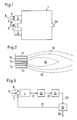
- Fig. 1 die Brennkammer im Längsschnitt in schematischer Darstellung,
- Fig. 2 den Mündungsbereich eines Brenners im Längsschnitt und
- Fig. 3 ein Fließbild für die Gasbehandlung.
- Die Brennkammer (1) weist mehrere Brenner (2,3) sowie eine an sich bekannte Stützfeuerung (4) auf. Dem Brenner (2) wird durch die Leitung (6) Sauerstoff, durch die Leitung (7) das Einsatzgas und durch die Leitung (8) Luft zugeführt. Wegen der besseren Übersichtlichkeit wurden die gleichen Zuleitungen zum Brenner (3) weggelassen. Der Stützfeuerung (4) führt man durch die Leitung (10) gasförmigen Brennstoff und durch die Leitung (11) Luft zu.
- Der Mündungsbereich eines Brenners besteht aus konzentrischen Rohren, die in Fig. 2 zu sehen sind. Durch das an der Mündung verengte Zentralrohr (13) strömt der Sauerstoff und verläßt das Rohr mit Strömungsgeschwindigkeiten von 50 bis 250 m/sec. Das Zentralrohr (13) umgibt ein zweites Rohr (14), durch welches das Einsatzgas in die Verbrennung geleitet wird. Das Einsatzgas enthält neben H₂S noch mindestens 5 Vol.% an Kohlenwasserstoffen oder CO₂. Die Strömungsgeschwindigkeit des Einsatzgases beträgt beim Verlassen des zweiten Rohrs 10 bis 30 m/sec. Durch das äußere Rohr (15) wird Luft herangeführt.
- Durch die Brenneranordnung sowie die Gase und ihre Strömungsgeschwindigkeiten entsteht eine Flammenstruktur, welche die erwünschten Reaktionen begünstigt. In der Kernzone (18) der Brennerflamme liegen die Temperaturen im Bereich von 2000 bis 3000°C und vorzugsweise mindestens 2300°, wodurch die Umwandlung von CO₂ in CO und Sauerstoff sowie die thermische Zersetzung von Wasser begünstigt wird. Die Lufthülle (19), welche den heißen Bereich der Flamme umgibt, schützt durch ihre relativ niedrigen Temperaturen die Ausmauerung der Brennkammer und wirkt der Abkühlung des Kernbereichs (18) der Flamme entgegen. In der Lufthülle (19) der Flamme liegen die Temperaturen etwa im Bereich von 800 bis 1300°C. In der Nähe des Auslasses (20) der Brennkammer stellen sich Temperaturen von etwa 1350 bis 1650°C ein. Das Gasgemisch mit diesen Temperaturen weist mindestens 2 Vol.% Kohlenmonoxid und mindestens 8 Vol.% Wasserstoff auf. Dieses Gasgemisch enthält nun auch SO₂, welches durch Verbrennung eines Teils des H₂S entstanden ist.
- Gemäß Fig. 3 wird das Gasgemisch aus der Brennkammer (1) durch die Leitung (21) zu einer Clausanlage (22) geführt, wo an Katalysatoren bei Temperaturen von zunächst etwa 320 bis schließlich etwa 200°C H₂S mit SO₂ zu Elementarschwefel in bekannter Weise umgesetzt wird. Die bekannten Katalysatoren bestehen z.B. im wesentlichen aus TiO₂ und Al₂O₃, die in verschiedenen Festbetten angeordnet sind. Das Abgas der Clausanlage gelangt in der Leitung (23) zu einer Hydrolysezone (24), in welcher die im Gasgemisch vorhandenen Komponenten hydrolysierend und hydrierend behandelt werden. Da das Abgas genügend Wasserstoff enthält, ist es nicht erforderlich, für diese Hydrierung fremden Wasserstoff heranzuführen.
- Zur Hydrolysezone und der darin gleichzeitig erfolgenden Hydrierung ist folgendes zu erläutern: Über einen Katalysator, der z.B. aus Al₂O₃ als Träger und einer Co- und Mo-Imprägnierung besteht, werden restliches COS und CS₂ mit Wasserdampf zu H₂S hydrolysiert. Gleichzeitig werden restlicher Elementarschwefel und SO₂ mit Wasserstoff zu H₂S hydriert. Die Hydrolyse und die Hydrierung erfolgen am gleichen Katalysator, der im Festbett angeordnet ist, bei Temperaturen von etwa 300 bis 350°C. Das behandelte Gas besteht nun noch im wesentlichen aus H₂S, N₂, CO und H₂. Dieses Gasgemisch führt man durch die Leitung (25) einer Trennanlage (26) zu, in welcher man z.B. durch chemische Absorption z.B. mittels Methyldiethylenaminen (MDEA) H₂S abtrennt. Abgetrenntes H₂S führt man in der Leitung (27) zurück zur Brennkammer (1), CO, H₂ und N₂ stehen als Gasgemisch zur Weiterverwendung in der Leitung (28) zur Verfügung.
- Ein Einsatzgas mit der Zusammensetzung, trocken gerechnet,
H₂S 86,0 Vol.% CO 0,2 Vol.% CH₄ 1,0 Vol.% CO₂ 10,7 Vol.% N₂ 2,0 Vol.% H₂ 0,1 Vol.% A B C Luftmenge (Nm³) 438 182 105 Sauerstoffmenge (Nm³) 254 296 309 Stickstoff-Sauerstoff-Volumenverhältnis 1:1 0,4:1 0,25:1 Brennkammer-Temperatur am Auslaß (°C) 1427 1480 1497 Maximale Flammentemperatur (°C) 2500 2600 2800 - Das die Brennkammer (1) verlassende Gasgemisch hat folgende Zusammensetzung (Vol.%):
A B C H₂S 8,3 9,5 9,9 SO₂ 4,8 5,5 5,7 H₂O 41,0 46,6 48,6 COS 0,8 0,9 1,0 CS₂ 0,2 0,3 0,3 CO 3,5 4,5 4,8 CO₂ 3,6 3,8 3,9 H₂ 10,9 14,2 15,4 N₂ 25,0 13,0 8,6 weitere Schwefelverbindungen 1,9 1,7 1,8 100,0 100,0 100,0 Gasmenge: ohne Elementarschwefel (Nm³) 1436 1232 1172 mit Elementarschwefel (Nm³) 1761 1558 1498 - Dieses Gasgemisch wird einer zweistufigen Clausgaskatalyse unterworfen, wobei man als Katalysatoren in der ersten Stufe TiO₂ und in der zweiten Stufe Al₂O₃ verwendet. Dabei gewinnt man 97 % des Schwefels zurück.
- Das Abgas der Clausgaskatalyse wird hydriert und hydrolysiert, wobei man folgendermaßen arbeitet: Das Gasgemisch wird auf 320°C aufgeheizt und einem Reaktor zugeführt, in welchem die Hydrierung und Hydrolyse über ein und demselben Katalysator (Al₂O₃ imprägniert mit Co und Mo) erfolgt. In dem so behandelten Gasgemisch liegen alle Schwefelverbindungen nur noch als H₂S vor; das bei den Umsetzungen gebildete Wasser wird bis auf 4 Vol.% entfernt. Aus dem Gasgemisch entfernt man anschließend in einer Trennanlage mittels MDEA nach dem Sulften-Verfahren der Firma Ford, Bacon and Davis Inc., Dallas (USA), das H₂S bis auf etwa 10 Vol.-ppm und erhält ein Restgas in der Leitung (28) mit folgender Zusammensetzung:
A B C H₂ 19,1 29,7 34,8 CO 6,9 10,5 12,2 CO₂ 8,9 11,1 12,2 N₂ 61,1 44,7 36,8 H₂O 4,0 4,0 4,0 - Dieses Gasgemisch, insbesondere der Beispiele B und C, kann z.B. bei der hydrierenden Entschwefelung von Erdölprodukten oder als Heizgas verwendet werden.
Claims (3)
Priority Applications (1)
| Application Number | Priority Date | Filing Date | Title |
|---|---|---|---|
| AT88201637T ATE60749T1 (de) | 1987-10-16 | 1988-07-29 | Verfahren zum verbrennen eines schwefelwasserstoffhaltigen gases. |
Applications Claiming Priority (2)
| Application Number | Priority Date | Filing Date | Title |
|---|---|---|---|
| DE3735002 | 1987-10-16 | ||
| DE19873735002 DE3735002A1 (de) | 1987-10-16 | 1987-10-16 | Verfahren zum entfernen von schwefelwasserstoff aus abgas |
Publications (2)
| Publication Number | Publication Date |
|---|---|
| EP0315225A1 true EP0315225A1 (de) | 1989-05-10 |
| EP0315225B1 EP0315225B1 (de) | 1991-02-06 |
Family
ID=6338429
Family Applications (1)
| Application Number | Title | Priority Date | Filing Date |
|---|---|---|---|
| EP88201637A Expired - Lifetime EP0315225B1 (de) | 1987-10-16 | 1988-07-29 | Verfahren zum Verbrennen eines schwefelwasserstoffhaltigen Gases |
Country Status (11)
| Country | Link |
|---|---|
| US (1) | US4933163A (de) |
| EP (1) | EP0315225B1 (de) |
| JP (1) | JPH01141807A (de) |
| CN (1) | CN1012165B (de) |
| AT (1) | ATE60749T1 (de) |
| CA (1) | CA1306096C (de) |
| DE (2) | DE3735002A1 (de) |
| ES (1) | ES2020597B3 (de) |
| GR (1) | GR3001609T3 (de) |
| IN (1) | IN168511B (de) |
| NO (1) | NO169701C (de) |
Cited By (9)
| Publication number | Priority date | Publication date | Assignee | Title |
|---|---|---|---|---|
| EP0633220A1 (de) * | 1993-07-09 | 1995-01-11 | The BOC Group plc | Ein Gasreaktor/Brenner |
| EP0701967A1 (de) | 1994-09-19 | 1996-03-20 | The BOC Group plc | Verfahren zur Herstellung von Schwefel |
| FR2730721A1 (fr) * | 1995-02-21 | 1996-08-23 | Air Liquide | Procede d'oxydation partielle d'un flux de gaz comprenant du sulfure d'hydrogene |
| EP0901984A1 (de) | 1997-09-12 | 1999-03-17 | The BOC Group plc | Umsetzung eines Stromes eines brennbaren Gases |
| US6352680B1 (en) * | 1998-06-29 | 2002-03-05 | The Boc Group Plc | Partial combustion of hydrogen sulphide |
| WO2010124671A1 (de) * | 2009-04-28 | 2010-11-04 | Lurgi Gmbh | Verfahren zum herstellen von prozessgas für das claus-verfahren |
| WO2013098328A1 (en) * | 2011-12-27 | 2013-07-04 | Shell Internationale Research Maatschappij B.V. | Improved method for recovery of elemental sulphur |
| EP3553378A1 (de) | 2018-04-13 | 2019-10-16 | Linde Aktiengesellschaft | Verfahren und brenner zur verbrennung von schwefelwasserstoff |
| EP4462022A1 (de) | 2023-05-11 | 2024-11-13 | Selas-Linde GmbH | Verfahren und vorrichtung zum betreiben eines brenners |
Families Citing this family (32)
| Publication number | Priority date | Publication date | Assignee | Title |
|---|---|---|---|---|
| US5139764A (en) * | 1988-01-21 | 1992-08-18 | Union Carbide Industrial Gases Technology Corporation | Sulfur recovery process for ammonia-containing feed gas |
| US5139765A (en) * | 1988-01-21 | 1992-08-18 | Union Carbide Industrial Gases Technology Corporation | Dual combustion zone sulfur recovery process |
| DE4014018A1 (de) * | 1990-05-01 | 1991-11-07 | Metallgesellschaft Ag | Verfahren zum reinigen eines h(pfeil abwaerts)2(pfeil abwaerts)s und co(pfeil abwaerts)2(pfeil abwaerts) enthaltenden gases |
| US5174746A (en) * | 1990-05-11 | 1992-12-29 | Sumitomo Metal Mining Company Limited | Method of operation of flash smelting furnace |
| GB9103382D0 (en) * | 1991-02-19 | 1991-04-03 | Boc Group Plc | Treatment of gases |
| DE4109891A1 (de) * | 1991-03-26 | 1992-10-01 | Metallgesellschaft Ag | Verfahren zum erzeugen von elementarschwefel aus einem h(pfeil abwaerts)2(pfeil abwaerts)s enthaltenden gas |
| NL9200486A (nl) * | 1992-03-16 | 1993-10-18 | Hoogovens Groep Bv | Keramische brander voor een brandschacht van een windverhitter van een hoogoven. |
| US5454712A (en) * | 1993-09-15 | 1995-10-03 | The Boc Group, Inc. | Air-oxy-fuel burner method and apparatus |
| US5554022A (en) * | 1994-10-14 | 1996-09-10 | Xothermic, Inc. | Burner apparatus and method |
| US5743723A (en) * | 1995-09-15 | 1998-04-28 | American Air Liquide, Inc. | Oxy-fuel burner having coaxial fuel and oxidant outlets |
| CN1056542C (zh) * | 1996-04-30 | 2000-09-20 | 李晓东 | 气体中硫化氢的催化焚烧工艺 |
| EP0898687B1 (de) | 1996-05-17 | 2002-08-14 | Xothermic, Inc. | Brenner |
| US5681162A (en) * | 1996-09-23 | 1997-10-28 | Nabors, Jr.; James K. | Low pressure atomizer |
| US5904475A (en) * | 1997-05-08 | 1999-05-18 | Praxair Technology, Inc. | Dual oxidant combustion system |
| DE19860479C1 (de) * | 1998-12-28 | 2000-08-03 | Metallgesellschaft Ag | Brenner für die partielle Oxidation von flüssigen, kohlenstoffhaltigen Brennstoffen |
| FR2788110B1 (fr) * | 1998-12-30 | 2001-02-16 | Air Liquide | Procede de combustion et ses utilisations pour l'elaboration de verre et de metal |
| JP2000257811A (ja) * | 1999-03-03 | 2000-09-22 | Hitachi Ltd | 微粉炭燃焼方法及び微粉炭燃焼装置並びに微粉炭燃焼バーナ |
| DE19931373A1 (de) * | 1999-07-07 | 2001-01-11 | Metallgesellschaft Ag | Brenner für die partielle Oxidation von flüssigen, kohlenstoffhaltigen Brennstoffen |
| GB9930562D0 (en) * | 1999-12-23 | 2000-02-16 | Boc Group Plc | Partial oxidation of hydrogen sulphide |
| FR2814796B1 (fr) * | 2000-10-03 | 2003-08-29 | Air Liquide | Bruleur tri-tubes pour fours notamment a verre et a metaux, et procede d'injection de combustible et de carburant par un tel bruleur |
| FR2816037B1 (fr) * | 2000-11-02 | 2003-01-03 | Air Liquide | Bruleur et procede d'oxydation partielle d'un flux de gaz comprenant du sulfure d'hydrogene et le l'ammoniac |
| GB0204224D0 (en) * | 2002-02-22 | 2002-04-10 | Boc Group Plc | Partial oxidation of hydrogen sulphide |
| US7430970B2 (en) * | 2005-06-30 | 2008-10-07 | Larue Albert D | Burner with center air jet |
| CN101480559B (zh) * | 2008-01-09 | 2011-04-20 | 中国石油化工股份有限公司 | 一种用膜回收烟气中硫的方法 |
| DE102008008769A1 (de) | 2008-02-12 | 2009-08-20 | Lurgi Gmbh | Verfahren zum Gewinnen von Schwefel aus H2S enthaltendem Einsatzgas |
| DE102008050088A1 (de) * | 2008-10-06 | 2010-04-22 | Uhde Gmbh | Verfahren zur Entschwefelung |
| CA2763447C (en) * | 2009-06-10 | 2017-10-31 | Metso Power Ab | Method for precipitating lignin from black liquor by utilizing waste gases |
| PL2784022T3 (pl) * | 2013-03-28 | 2015-10-30 | Linde Ag | Stosowanie tlenu w jednostkach Clausa załadowanych dodatkowym ładunkiem -zwłaszcza strumieniem gazu odpadowego zawierającym SO2 i pochodzącym z regeneracji adsorbentu |
| CN109307262A (zh) * | 2017-07-26 | 2019-02-05 | Wte-技术有限责任公司 | 处理含有硫化合物的气态供料的方法 |
| JP6863189B2 (ja) * | 2017-09-05 | 2021-04-21 | トヨタ自動車株式会社 | 水素ガスバーナー装置用のノズル構造体 |
| KR102325814B1 (ko) * | 2019-08-21 | 2021-11-11 | 씨에스케이(주) | 스크러버용 버너 |
| EP4310394B1 (de) | 2022-07-21 | 2025-05-21 | L'air Liquide, Société Anonyme Pour L'Étude Et L'exploitation Des Procédés Georges Claude | Brenneranordnung für die synthesegaserzeugung |
Citations (3)
| Publication number | Priority date | Publication date | Assignee | Title |
|---|---|---|---|---|
| US3963443A (en) * | 1974-09-23 | 1976-06-15 | Ford, Bacon & Davis Texas Incorporated | Acid gas burner and sulfur recovery system |
| CA1004832A (en) * | 1970-08-26 | 1977-02-08 | British Gas Corporation | Recovery of sulphur from gases containing h2s and so2 |
| DE3430015C1 (de) * | 1984-08-16 | 1986-05-07 | Metallgesellschaft Ag, 6000 Frankfurt | Vorrichtung zum Verbrennen von schwefelwasserstoffhaltigem Gas zum Erzeugen eines Prozeßgases für das Claus-Verfahren |
Family Cites Families (19)
| Publication number | Priority date | Publication date | Assignee | Title |
|---|---|---|---|---|
| NL48387C (de) * | 1936-06-14 | |||
| BE509691A (de) * | 1951-03-06 | |||
| NL285334A (de) * | 1962-01-13 | 1900-01-01 | ||
| US3209811A (en) * | 1963-03-28 | 1965-10-05 | Loftus Engineering Corp | Combination high velocity burner |
| US3364970A (en) * | 1967-04-03 | 1968-01-23 | Messer Griesheim Gmbh | Cutting torch nozzle and method |
| DE1903595A1 (de) * | 1968-01-25 | 1969-10-09 | Daido Sanso Kabushiki Kaisha O | Verfahren und Vorrichtung zum fortlaufenden Erzeugen einer Flamme von hoher Temperatur |
| GB1406085A (en) * | 1972-09-15 | 1975-09-10 | Shell Int Research | Process for the recovery of sulphur from hydrogen sulphide and sulphur dioxide |
| US3860697A (en) * | 1973-04-23 | 1975-01-14 | Amoco Prod Co | Method for recovery of elemental sulfur from low hydrogen sulfide sulfur plant feed gas |
| US4035158A (en) * | 1975-04-25 | 1977-07-12 | John Zink Company | Process and apparatus for burning hydrogen sulfide and other combustible fluid to recover sulfur |
| DE2613343C3 (de) * | 1976-03-29 | 1980-08-28 | Davy International Ag, 6000 Frankfurt | Verfahren zur Gewinnung von Schwefel aus SO2 -haltigen Gasen |
| DE2648190C3 (de) * | 1976-10-25 | 1980-02-21 | Metallgesellschaft Ag, 6000 Frankfurt | Verfahren zur Herstellung von Schwefel nach dem Claus-Verfahren |
| DE2908427C2 (de) * | 1979-03-05 | 1983-04-14 | L. & C. Steinmüller GmbH, 5270 Gummersbach | Verfahren zur Verminderung der NO↓X↓-Emission bei der Verbrennung von stickstoffhaltigen Brennstoffen |
| EP0034848B1 (de) * | 1980-02-26 | 1984-04-18 | Shell Internationale Researchmaatschappij B.V. | Verfahren zur Verbrennung von Ammoniak enthaltenden Gasen, welche auch Schwefelwasserstoff enthalten |
| US4481181A (en) * | 1982-02-08 | 1984-11-06 | Ga Technologies Inc. | Hydrogen production from in situ partial burning of H2 S |
| US4501725A (en) * | 1983-03-31 | 1985-02-26 | Davy Mckee Ag | Process for the combustion of H2 S containing gases |
| DE3415722A1 (de) * | 1984-04-27 | 1985-10-31 | Metallgesellschaft Ag, 6000 Frankfurt | Verfahren zum entfernen von schwefelwasserstoff aus abgas und zum erzeugen von in schwefel nach dem claus-prozess |
| US4575453A (en) * | 1984-11-13 | 1986-03-11 | Amoco Corporation | Modified Claus furnace |
| CN1007920B (zh) * | 1985-07-15 | 1990-05-09 | 美国氧化公司 | 烃类流体燃料燃烧、控制方法及装置 |
| US4780305A (en) * | 1986-10-03 | 1988-10-25 | The Ralph M. Parsons Company | Dual combustion oxygen-enriched claus sulfur plant |
-
1987
- 1987-10-16 DE DE19873735002 patent/DE3735002A1/de not_active Withdrawn
-
1988
- 1988-02-12 IN IN125/CAL/88A patent/IN168511B/en unknown
- 1988-07-29 DE DE8888201637T patent/DE3861760D1/de not_active Expired - Lifetime
- 1988-07-29 ES ES88201637T patent/ES2020597B3/es not_active Expired - Lifetime
- 1988-07-29 EP EP88201637A patent/EP0315225B1/de not_active Expired - Lifetime
- 1988-07-29 AT AT88201637T patent/ATE60749T1/de not_active IP Right Cessation
- 1988-08-19 NO NO883733A patent/NO169701C/no not_active IP Right Cessation
- 1988-08-23 CA CA000575420A patent/CA1306096C/en not_active Expired - Lifetime
- 1988-09-20 US US07/247,029 patent/US4933163A/en not_active Expired - Lifetime
- 1988-10-15 JP JP63260346A patent/JPH01141807A/ja active Granted
- 1988-10-15 CN CN88107101A patent/CN1012165B/zh not_active Expired
-
1991
- 1991-03-15 GR GR90400900T patent/GR3001609T3/el unknown
Patent Citations (3)
| Publication number | Priority date | Publication date | Assignee | Title |
|---|---|---|---|---|
| CA1004832A (en) * | 1970-08-26 | 1977-02-08 | British Gas Corporation | Recovery of sulphur from gases containing h2s and so2 |
| US3963443A (en) * | 1974-09-23 | 1976-06-15 | Ford, Bacon & Davis Texas Incorporated | Acid gas burner and sulfur recovery system |
| DE3430015C1 (de) * | 1984-08-16 | 1986-05-07 | Metallgesellschaft Ag, 6000 Frankfurt | Vorrichtung zum Verbrennen von schwefelwasserstoffhaltigem Gas zum Erzeugen eines Prozeßgases für das Claus-Verfahren |
Cited By (15)
| Publication number | Priority date | Publication date | Assignee | Title |
|---|---|---|---|---|
| EP0633220A1 (de) * | 1993-07-09 | 1995-01-11 | The BOC Group plc | Ein Gasreaktor/Brenner |
| EP0701967A1 (de) | 1994-09-19 | 1996-03-20 | The BOC Group plc | Verfahren zur Herstellung von Schwefel |
| FR2730721A1 (fr) * | 1995-02-21 | 1996-08-23 | Air Liquide | Procede d'oxydation partielle d'un flux de gaz comprenant du sulfure d'hydrogene |
| WO1996026157A1 (fr) * | 1995-02-21 | 1996-08-29 | L'air Liquide, Societe Anonyme Pour L'etude Et L'exploitation Des Procedes Georges Claude | Procede d'oxydation partielle d'un flux de gaz comprenant du sulfure d'hydrogene |
| AU692066B2 (en) * | 1995-02-21 | 1998-05-28 | L'air Liquide, Societe Anonyme Pour L'etude Et L'exploitation Des Procedes Georges Claude | Method for partially oxidising a gas stream containing hydrogen sulphide |
| US6328940B1 (en) | 1995-02-21 | 2001-12-11 | L'air Liquide, Societe Anonyme Pour L'etude Et L'exploitation Des Procedes Georges Claude | Process for partial oxidation of a gas stream containing hydrogen sulphide |
| US6312651B1 (en) | 1997-09-12 | 2001-11-06 | The Boc Group Plc | Apparatus for burning a combustible gas containing hydrogen sulfide |
| EP0901984A1 (de) | 1997-09-12 | 1999-03-17 | The BOC Group plc | Umsetzung eines Stromes eines brennbaren Gases |
| US6531109B2 (en) | 1997-09-12 | 2003-03-11 | The Boc Group, Plc | Treatment of a combustible gas stream |
| US6352680B1 (en) * | 1998-06-29 | 2002-03-05 | The Boc Group Plc | Partial combustion of hydrogen sulphide |
| WO2010124671A1 (de) * | 2009-04-28 | 2010-11-04 | Lurgi Gmbh | Verfahren zum herstellen von prozessgas für das claus-verfahren |
| US8431105B2 (en) | 2009-04-28 | 2013-04-30 | Lurgi Gmbh | Method for producing process gas for the claus process |
| WO2013098328A1 (en) * | 2011-12-27 | 2013-07-04 | Shell Internationale Research Maatschappij B.V. | Improved method for recovery of elemental sulphur |
| EP3553378A1 (de) | 2018-04-13 | 2019-10-16 | Linde Aktiengesellschaft | Verfahren und brenner zur verbrennung von schwefelwasserstoff |
| EP4462022A1 (de) | 2023-05-11 | 2024-11-13 | Selas-Linde GmbH | Verfahren und vorrichtung zum betreiben eines brenners |
Also Published As
| Publication number | Publication date |
|---|---|
| CA1306096C (en) | 1992-08-11 |
| DE3861760D1 (de) | 1991-03-14 |
| CN1012165B (zh) | 1991-03-27 |
| JPH0512283B2 (de) | 1993-02-17 |
| NO169701B (no) | 1992-04-21 |
| ATE60749T1 (de) | 1991-02-15 |
| US4933163A (en) | 1990-06-12 |
| NO883733D0 (no) | 1988-08-19 |
| EP0315225B1 (de) | 1991-02-06 |
| NO169701C (no) | 1992-08-05 |
| JPH01141807A (ja) | 1989-06-02 |
| NO883733L (no) | 1989-04-17 |
| GR3001609T3 (en) | 1992-11-23 |
| CN1034181A (zh) | 1989-07-26 |
| DE3735002A1 (de) | 1989-04-27 |
| IN168511B (de) | 1991-04-20 |
| ES2020597B3 (es) | 1991-08-16 |
Similar Documents
| Publication | Publication Date | Title |
|---|---|---|
| EP0315225B1 (de) | Verfahren zum Verbrennen eines schwefelwasserstoffhaltigen Gases | |
| EP0671453B1 (de) | Verfahren zum Erzeugen von Holzkohle im Wanderbett | |
| DE3224328C2 (de) | Verfahren und Anlage zur Umwandlung von Abfallstoffen, welche thermisch zersetzbare, chemische Substanzen enthalten | |
| EP4363372A1 (de) | Verfahren und vorrichtung zur erzeugung von wasserstoff aus ammoniak | |
| DE1229500B (de) | Wasserstoff-Generator | |
| DE2827872A1 (de) | Verfahren zur herstellung von furnaceruss | |
| DE102009018911A1 (de) | Verfahren zum Herstellen von Prozessgas für das Claus-Verfahren | |
| EP0977708A1 (de) | Verfahren und vorrichtung zur umwandlung von schwefelwasserstoff in elementaren schwefel | |
| DE3636024C2 (de) | ||
| EP0010779B1 (de) | Verfahren zur Erzeugung von Stadtgas aus Methanol | |
| EP3202922B1 (de) | Verfahren und anlage zur herstellung von eisenschwamm | |
| EP0506161B1 (de) | Verfahren zum Erzeugen von Elementarschwefel aus einem Schwefelwasserstoff enthaltenden Gas | |
| DE3308406C2 (de) | ||
| DE2117236A1 (de) | Verfahren und Vorrichtung zur oxydierenden Spaltung von Kohlenwasserstoffen | |
| EP0324207B1 (de) | Verfahren zum Erzeugen eines kohlenmonoxidreichen Gases durch Spalten von Kohlenwasserstoffen | |
| DE3310902C2 (de) | ||
| DE2141875A1 (de) | Verfahren zur herstellung eines reduktionsgases | |
| DE3430015C1 (de) | Vorrichtung zum Verbrennen von schwefelwasserstoffhaltigem Gas zum Erzeugen eines Prozeßgases für das Claus-Verfahren | |
| DD155998A5 (de) | Verfahren zur herstellung von gasen aus schweroelen | |
| DE1467119B2 (de) | Verfahren und vorrichtung zur rueckgewinnung von elementarem schwefel aus einem schwefelwasserstoffhaltigen gasstrom mit einem geringen gehalt an brennbaren stoffen | |
| DE1567728B2 (de) | Verfahren zur erzeugung eines an wasserstoff und kohlenstoff reichen gases aus kohlendestillationsgasen | |
| DE917561C (de) | Verfahren und Einrichtung zur Herstellung eines kohlenmonosydarmen Stadtgases | |
| DE2463388C2 (de) | Verfahren zur Gewinnung von freiem Schwefel aus einem Beschickungsstrom, der eine Schwefelwasserstoffmenge enthält, die zur Aufrechterhaltung in einem Direktoxidationsprozeß nicht ausreicht | |
| DE102019003985A1 (de) | Verfahren und Vorrichtung zur Schwefelgewinnung | |
| DE2137151C3 (de) | Verfahren zur Herstellung von Synthesegas |
Legal Events
| Date | Code | Title | Description |
|---|---|---|---|
| PUAI | Public reference made under article 153(3) epc to a published international application that has entered the european phase |
Free format text: ORIGINAL CODE: 0009012 |
|
| AK | Designated contracting states |
Kind code of ref document: A1 Designated state(s): AT BE DE ES FR GB GR IT NL SE |
|
| 17P | Request for examination filed |
Effective date: 19890620 |
|
| 17Q | First examination report despatched |
Effective date: 19900516 |
|
| GRAA | (expected) grant |
Free format text: ORIGINAL CODE: 0009210 |
|
| AK | Designated contracting states |
Kind code of ref document: B1 Designated state(s): AT BE DE ES FR GB GR IT NL SE |
|
| REF | Corresponds to: |
Ref document number: 60749 Country of ref document: AT Date of ref document: 19910215 Kind code of ref document: T |
|
| REF | Corresponds to: |
Ref document number: 3861760 Country of ref document: DE Date of ref document: 19910314 |
|
| ET | Fr: translation filed | ||
| ITF | It: translation for a ep patent filed | ||
| GBT | Gb: translation of ep patent filed (gb section 77(6)(a)/1977) | ||
| PLBE | No opposition filed within time limit |
Free format text: ORIGINAL CODE: 0009261 |
|
| STAA | Information on the status of an ep patent application or granted ep patent |
Free format text: STATUS: NO OPPOSITION FILED WITHIN TIME LIMIT |
|
| 26N | No opposition filed | ||
| REG | Reference to a national code |
Ref country code: GR Ref legal event code: FG4A Free format text: 3001609 |
|
| EAL | Se: european patent in force in sweden |
Ref document number: 88201637.1 |
|
| REG | Reference to a national code |
Ref country code: GB Ref legal event code: IF02 |
|
| PGFP | Annual fee paid to national office [announced via postgrant information from national office to epo] |
Ref country code: DE Payment date: 20070719 Year of fee payment: 20 |
|
| PGFP | Annual fee paid to national office [announced via postgrant information from national office to epo] |
Ref country code: ES Payment date: 20070727 Year of fee payment: 20 |
|
| PGFP | Annual fee paid to national office [announced via postgrant information from national office to epo] |
Ref country code: AT Payment date: 20070716 Year of fee payment: 20 |
|
| PGFP | Annual fee paid to national office [announced via postgrant information from national office to epo] |
Ref country code: GB Payment date: 20070720 Year of fee payment: 20 |
|
| PGFP | Annual fee paid to national office [announced via postgrant information from national office to epo] |
Ref country code: BE Payment date: 20070802 Year of fee payment: 20 Ref country code: IT Payment date: 20070724 Year of fee payment: 20 Ref country code: NL Payment date: 20070716 Year of fee payment: 20 Ref country code: SE Payment date: 20070712 Year of fee payment: 20 |
|
| PGFP | Annual fee paid to national office [announced via postgrant information from national office to epo] |
Ref country code: FR Payment date: 20070710 Year of fee payment: 20 |
|
| PGFP | Annual fee paid to national office [announced via postgrant information from national office to epo] |
Ref country code: GR Payment date: 20070730 Year of fee payment: 20 |
|
| BE20 | Be: patent expired |
Owner name: *METALLGESELLSCHAFT A.G. Effective date: 20080729 |
|
| REG | Reference to a national code |
Ref country code: GB Ref legal event code: PE20 Expiry date: 20080728 |
|
| EUG | Se: european patent has lapsed | ||
| NLV7 | Nl: ceased due to reaching the maximum lifetime of a patent |
Effective date: 20080729 |
|
| REG | Reference to a national code |
Ref country code: ES Ref legal event code: FD2A Effective date: 20080730 |
|
| PG25 | Lapsed in a contracting state [announced via postgrant information from national office to epo] |
Ref country code: NL Free format text: LAPSE BECAUSE OF EXPIRATION OF PROTECTION Effective date: 20080729 |
|
| PG25 | Lapsed in a contracting state [announced via postgrant information from national office to epo] |
Ref country code: GB Free format text: LAPSE BECAUSE OF EXPIRATION OF PROTECTION Effective date: 20080728 |
|
| PG25 | Lapsed in a contracting state [announced via postgrant information from national office to epo] |
Ref country code: ES Free format text: LAPSE BECAUSE OF EXPIRATION OF PROTECTION Effective date: 20080730 |