EP0315236A2 - Dispositif à galets de manutention du fret pour avion - Google Patents
Dispositif à galets de manutention du fret pour avion Download PDFInfo
- Publication number
- EP0315236A2 EP0315236A2 EP88202311A EP88202311A EP0315236A2 EP 0315236 A2 EP0315236 A2 EP 0315236A2 EP 88202311 A EP88202311 A EP 88202311A EP 88202311 A EP88202311 A EP 88202311A EP 0315236 A2 EP0315236 A2 EP 0315236A2
- Authority
- EP
- European Patent Office
- Prior art keywords
- rollers
- cargo
- drive shaft
- cylinder
- motor
- Prior art date
- Legal status (The legal status is an assumption and is not a legal conclusion. Google has not performed a legal analysis and makes no representation as to the accuracy of the status listed.)
- Granted
Links
- 230000008878 coupling Effects 0.000 claims abstract description 12
- 238000010168 coupling process Methods 0.000 claims abstract description 12
- 238000005859 coupling reaction Methods 0.000 claims abstract description 12
- 230000009849 deactivation Effects 0.000 claims description 3
- 230000004913 activation Effects 0.000 claims 1
- 230000000712 assembly Effects 0.000 abstract description 2
- 238000000429 assembly Methods 0.000 abstract description 2
- 239000007787 solid Substances 0.000 description 5
- 230000004048 modification Effects 0.000 description 2
- 238000012986 modification Methods 0.000 description 2
- 229920000459 Nitrile rubber Polymers 0.000 description 1
- 238000010276 construction Methods 0.000 description 1
- 230000007423 decrease Effects 0.000 description 1
- 238000010586 diagram Methods 0.000 description 1
- 239000000463 material Substances 0.000 description 1
- 229920001084 poly(chloroprene) Polymers 0.000 description 1
Images

Classifications
-
- B—PERFORMING OPERATIONS; TRANSPORTING
- B65—CONVEYING; PACKING; STORING; HANDLING THIN OR FILAMENTARY MATERIAL
- B65G—TRANSPORT OR STORAGE DEVICES, e.g. CONVEYORS FOR LOADING OR TIPPING, SHOP CONVEYOR SYSTEMS OR PNEUMATIC TUBE CONVEYORS
- B65G13/00—Roller-ways
- B65G13/02—Roller-ways having driven rollers
- B65G13/06—Roller driving means
- B65G13/073—Roller driving means comprising free-wheel gearing
-
- B—PERFORMING OPERATIONS; TRANSPORTING
- B65—CONVEYING; PACKING; STORING; HANDLING THIN OR FILAMENTARY MATERIAL
- B65G—TRANSPORT OR STORAGE DEVICES, e.g. CONVEYORS FOR LOADING OR TIPPING, SHOP CONVEYOR SYSTEMS OR PNEUMATIC TUBE CONVEYORS
- B65G67/00—Loading or unloading vehicles
- B65G67/02—Loading or unloading land vehicles
- B65G67/04—Loading land vehicles
- B65G67/20—Loading covered vehicles
-
- Y—GENERAL TAGGING OF NEW TECHNOLOGICAL DEVELOPMENTS; GENERAL TAGGING OF CROSS-SECTIONAL TECHNOLOGIES SPANNING OVER SEVERAL SECTIONS OF THE IPC; TECHNICAL SUBJECTS COVERED BY FORMER USPC CROSS-REFERENCE ART COLLECTIONS [XRACs] AND DIGESTS
- Y10—TECHNICAL SUBJECTS COVERED BY FORMER USPC
- Y10T—TECHNICAL SUBJECTS COVERED BY FORMER US CLASSIFICATION
- Y10T74/00—Machine element or mechanism
- Y10T74/19—Gearing
- Y10T74/19219—Interchangeably locked
- Y10T74/19251—Control mechanism
- Y10T74/19279—Cam operated
-
- Y—GENERAL TAGGING OF NEW TECHNOLOGICAL DEVELOPMENTS; GENERAL TAGGING OF CROSS-SECTIONAL TECHNOLOGIES SPANNING OVER SEVERAL SECTIONS OF THE IPC; TECHNICAL SUBJECTS COVERED BY FORMER USPC CROSS-REFERENCE ART COLLECTIONS [XRACs] AND DIGESTS
- Y10—TECHNICAL SUBJECTS COVERED BY FORMER USPC
- Y10T—TECHNICAL SUBJECTS COVERED BY FORMER US CLASSIFICATION
- Y10T74/00—Machine element or mechanism
- Y10T74/21—Elements
- Y10T74/2101—Cams
- Y10T74/2107—Follower
Definitions
- This invention pertains to cargo conveyors, and, more particularly, to a cargo roller system having rollers and a drive motor and a coupling assembly for selectively engaging and disengaging the drive motor and the rollers.
- Floor-mounted powered cargo systems are used to facilitate movement of cargo containers inside the main deck and lower lobe compartments of wide-bodied aircraft. While movement of cargo inside an aircraft has traditionally been done by hand, the development of large and heavy cargo containers necessitates the use of a powered cargo system.
- One prior cargo system uses a plurality of pneumatic rollers, each roller being powered by an individual motor. The roller and motor unit is pivotally mounted in a floor recess. A disadvantage of this prior system is that the pneumatic rollers tend to lose air and go flat. Another disadvantage of this system is that the limited vertical floor space in an aircraft restricts the diameter of the roller.
- each roller is so small that for heavy containers or containers having slick bottom surfaces manual help is required to move them in the compartment. Furthermore, because of the recessed floor mounting, any repositioning of the units requires structural modification of the floor.
- the present invention overcomes the foregoing and other disadvantages by providing an aircraft cargo roller system having a plurality of drive rollers selectively engageable with a drive motor.
- the cargo roller system comprises one or more rotatable rollers coupled to a motor means by a rotatable coupler.
- the rotatable coupler comprises a first member coupled to the motor means, a second member engageable with the drive rollers, and a position control means connecting the first and second members together.
- the position control means is configured so that upon rotation of the first member by the motor means, the second member, when initially out of engagement with the drive rollers, will be first moved translationally along its longitudinal axis into engagement with the rollers, and then rotated to thereby rotate the drive rollers; and upon rotation of the motor means in an opposite direction, the second member will be first disengaged from the drive rollers, then engaged with the rollers, and then rotated to thereby rotate the drive rollers in the opposite direction.
- the position control means is further configured so that upon deactivation of the motor means, the second member of the position control means can be disengaged from the drive rollers upon manual rotation of the drive rollers.
- the second member of the rotatable coupler preferably comprises a shaft;
- the first member preferably comprises a cylinder having a wall and an internal axial bore for slidably receiving the shaft; and
- the position control means preferably comprises a cam means formed in the wall of the cylinder and follower means formed on the shaft to cooperate with the cam means for retaining and positioning the shaft within the internal axial bore of the cylinder.
- the follower means comprises a retaining pin insertable through the shaft and the cam means comprises one or more openings formed in the walls of the cylinder for receiving the retaining pin.
- the cargo roller system also includes a load limiting means that limits the load applied to the drive rollers by the cargo.
- the torque limiting means comprises one or more idler rollers in parallel axial alignment with the drive rollers. the one or more idler rollers have a diameter less than the diameter of the drive rollers to thereby limit the amount of load exerted on the drive rollers and to permit the drive rollers to slip with respect to the cargo when subjected to a predetermined load.
- a cylindrical sleeve is provided for attachment over the cylinder to cover the cylinder and the one or more openings to thereby hold the retaining pin in engagement with the shaft and the one or more openings.
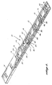
- the aicraft cargo roller system 10 comprises a plurality of rollers 12 mounted in an elongate roller tray 14 having a tray cover 15.
- the rollers 12 consist of drive rollers 13, constructed of a compressible roller tire 16 formed about a solid roller wheel 18 and idler rollers 19 constructed of a solid roller.
- the rollers 12 are supported by a roller bearing block 20 mounted to the tray 14 by fasteners 22. Passing through and extending out of each roller wheel 18 in an axle 24 that rests in grooves 26 formed in the bearing blocks 20.
- the rollers 12 are oriented in the bearing blocks 20 so that their longitudinal axis is transverse to the longitudinal axis of the tray 14. Caps 28 are fastened to the tops of the bearing blocks 20 to retain the axles 24 in the grooves 26.
- An electrically powered motor 30 is mounted in the tray 14 by a motor mount 32.
- a drive gear 34 is mounted to the shaft 36 of the motor 30.
- a beveled roller gear 38 is mounted to one end of the axles 24 of the rollers 12.
- the rollers 12 consist of six drive rollers 13 and two idler rollers 19, with the two idler rollers 19 having no gear on their axles 24. The function of these idler rollers 19 will be described in more detail below.
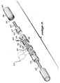
- the electrically powered motor 30 drives the drive rollers 13 through an assembly of gears generally denoted as gear train 44.
- the gear train 44 is mounted parallel to the longitudinal axis of the tray 14 and has a plurality of beveled gears 46 that mesh with the beveled roller gears 38 on the drive rollers 13.
- the motor 30 engages the gear train 44 through an idler gear 48 mounted in the motor mount 32 and a driven gear 50 mounted to the shaft 52 of the gear train 44.
- Also mounted on the shaft 52 are a plurality of bearings 54 for supporting the shaft in the plurality of openings 56 in the roller bearing blocks 20.
- torque dampers 58 are provided at spaced intervals between the beveled gears 46 to insure teeth engagement of the bevel gears 46 and 38 that occurs during rotation of the gear train 44.
- FIGURE 3 shows the internal construction of the coupling assembly 60, wherein the shaft 52 has a cylindrical piston 62 formed on the end thereof. An opening 64 passes transversely through the piston 62. A cylinder 66 is attached to each end of the drive shaft 68. The driven gear 50 is mounted on the drive shaft 68 between the two cylinders 66. Each cylinder 66 has an internal axial bore sized and shaped to slidably receive the piston 62 therein. A V-shaped opening 70 is formed in the outer wall 72 of the cylinder 66.
- a second V-shaped opening 70 is located on the opposite side of the cylinder wall 72.
- a retaining pin 74 passes through the V-shaped opening 70 and the opening 64 to retain the piston 62 in slidable engagement within the cylinder 66.
- a cylindrical sleeve 76 is slid over the piston 62 and cylinder 66 assembly and is threadably attached to the cylinder 66 by means of threads 78 on the exterior of the cylinder wall 72 which cooperate with internal threads 79 on the cylindrical sleeve.
- a set screw may be passed through an opening 80 in the cylindrical sleeve 76 to prevent the sleeve 76 from backing off the threads 78 on the cylinder 66.
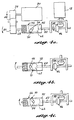
- FIGURES 4a-c illustrate the sequence of movements that take place during operation of the cargo roller system 10.
- the motor 30 is shown initially rotating the drive gear 34 in the direction indicated by the arrow.
- the drive gear 34 rotates the engaged idler gear 48 that in turn rotates the driven gear 50 in the same direction as the drive gear 34.
- the driven gear 50 through the shaft 68, rotates the cylinder 66.
- the retaining pin 74 protruding into the opening 70, becomes engaged by the cylinder wall 72.
- FIGURE 4b the motor 30 has stopped and begun reversing direction of rotation of the drive gear 34.
- the V-shaped openings 64 and 70 force the retaining pin 74 and the associated piston 62 to be pulled further within the internal axial bore of the cylinder 66, as indicated by the arrow.
- the motor 30 may then be shut off, thus keeping the gear train 44 disengaged from the drive rollers 13. This permits the drive rollers 13 to freely roll.
- FIGURES 4a-c also permits manual disengagement of the gears.
- the motor 30 be shut off while the beveled gear 46 is engaged with the roller gear 38, manual pressure on one or more of the drive rollers 13 will cause the roller gears 38 to put pressure on the beveled gears 46, urging them out of engagement.
- the shaft 52 and the piston 62 are moved to the left by the disengagement of the gears, as indicated in FIGURE 4b, the cylinder 66 will be forced to rotate in the direction indicated by the arrow.
- the de-energized motor 30 allows the driven gear 50 to rotate the drive gear 34 as the cylinder 66 is rotated by the disengaging gears, completing the disengagement.
- the outside diameter of the drive rollers 13 is preferably two inches.
- the roller tire 16 may be constructed from nitrile rubber or neoprene of preferably 70-80 shore hardness. The use of this material permits a limited amount of deflection of the roller tire 16 as the heavy cargo pallet bears down on it.
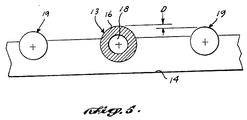
- FIGURE 5 is a cross-sectional pictorial illustration showing the drive roller 13 mounted in the roller tray 14. The roller tire 16 has a preferable thickness of approximately one-half inch and is bonded to the roller wheel 18. Also shown in FIGURE 5 are two idler rollers 19 mounted axially parallel to, and at the same axial height as, the drive roller 13.
- the idler rollers 19 function to limit the amount of load applied to the drive roller 13 in order to prevent damage to the gears or motor in overload conditions.
- the idler roller 19 is solid, and has an outside diameter smaller than the outside diameter of the drive roller 13.
- the amount of deflection D of the roller tire 16 will be limited. This permits the drive rollers 13 to slip with respect to the bottom surface of the cargo container should the cargo container be heavier than the load bearing capacity of the cargo roller system.
- the limitation on the amount of deflection may be varied by changing the outside diameter of the idler rollers 19.
- FIGURE 1 shows the preferred position of the idler rollers 19 as being immediately on either side of the motor 30, although they may be positioned further outboard.
- the present invention provides a cargo roller system that is of a small size, light weight, and easily relocatable.
- the unique cam-follower configuration of the coupler assembly permits selective engagement and disengagement of the electrically powered motor with the drive rollers.
- the coupling system permits manual disengagement of the rollers in the event of a power failure or an inoperative motor.
- the low profile of the roller tray facilitates relocation of the cargo roller system by not requiring modification of the existing floor structure.
- easy access is available to the internal structure of the cargo roller system through the quickly removable cover.
- the torque limiting feature achieved through the use of idler rollers provides protection to the gear train while eliminating the need for complex and heavier automatic slip devices.
Landscapes
- Engineering & Computer Science (AREA)
- Mechanical Engineering (AREA)
- Aviation & Aerospace Engineering (AREA)
- Rollers For Roller Conveyors For Transfer (AREA)
Applications Claiming Priority (2)
| Application Number | Priority Date | Filing Date | Title |
|---|---|---|---|
| US115383 | 1987-11-02 | ||
| US07/115,383 US4802572A (en) | 1987-11-02 | 1987-11-02 | Aircraft cargo roller system |
Publications (3)
| Publication Number | Publication Date |
|---|---|
| EP0315236A2 true EP0315236A2 (fr) | 1989-05-10 |
| EP0315236A3 EP0315236A3 (en) | 1989-10-25 |
| EP0315236B1 EP0315236B1 (fr) | 1992-04-01 |
Family
ID=22361052
Family Applications (1)
| Application Number | Title | Priority Date | Filing Date |
|---|---|---|---|
| EP88202311A Expired - Lifetime EP0315236B1 (fr) | 1987-11-02 | 1988-10-14 | Dispositif à galets de manutention du fret pour avion |
Country Status (3)
| Country | Link |
|---|---|
| US (1) | US4802572A (fr) |
| EP (1) | EP0315236B1 (fr) |
| DE (1) | DE3869735D1 (fr) |
Cited By (5)
| Publication number | Priority date | Publication date | Assignee | Title |
|---|---|---|---|---|
| DE4328978A1 (de) * | 1993-08-28 | 1995-03-02 | Deutsche Aerospace Airbus | Vorrichtung zum Tragen von Ladungseinheiten in Frachtladesystemen |
| WO2001021514A1 (fr) * | 1999-09-23 | 2001-03-29 | Space Srl | Appareil de chargement motorise pour camions et analogues |
| DE10324648A1 (de) * | 2003-05-30 | 2004-12-30 | Airbus Deutschland Gmbh | Vorrichtung zur Aufnahme von Zurrvorrichtungen für ein Frachtladesystem eines Transportmittels, insbesondere eines Flugzeuges |
| EP1332990A3 (fr) * | 2002-01-30 | 2005-02-09 | Okamura Corporation | Convoyeur à rouleaux |
| US7344013B2 (en) | 2005-04-15 | 2008-03-18 | Airbus Deutschland Gmbh | Loading support device for cargo spaces in a means of transport, in particular for cargo spaces in aircrafts |
Families Citing this family (8)
| Publication number | Priority date | Publication date | Assignee | Title |
|---|---|---|---|---|
| US5740695A (en) * | 1996-01-29 | 1998-04-21 | Ford Global Technologies, Inc. | Shift device for a manual transmission |
| US6122983A (en) * | 1997-12-22 | 2000-09-26 | Ford Global Technologies, Inc. | Shift device for a manual transmission |
| US6158574A (en) * | 1999-02-26 | 2000-12-12 | Williams; Dwon A. | Roller conveyor |
| US6389719B1 (en) * | 2000-05-16 | 2002-05-21 | Robotic Displays Corporation | Display device |
| TWI220412B (en) * | 2003-11-11 | 2004-08-21 | Benq Corp | Guiding and positioning apparatus |
| US20110222983A1 (en) * | 2010-03-11 | 2011-09-15 | Edward Dugic | Roller Assembly System and Method for Installation |
| US9522724B2 (en) | 2014-11-03 | 2016-12-20 | The Boeing Company | Roller covers and assemblies |
| US12116211B2 (en) * | 2022-04-20 | 2024-10-15 | Goodrich Corporation | Eccentric shaft blind spacer assembly |
Family Cites Families (13)
| Publication number | Priority date | Publication date | Assignee | Title |
|---|---|---|---|---|
| US778613A (en) * | 1904-08-15 | 1904-12-27 | Thomas J Tierney | Portable carrying-table. |
| US1221925A (en) * | 1913-03-06 | 1917-04-10 | Rolland S Trott | Control mechanism for motor-vehicles. |
| US1153605A (en) * | 1913-10-16 | 1915-09-14 | William F Clark | Furnace-charging apparatus. |
| DE890021C (de) * | 1952-03-23 | 1953-09-17 | Daimler Benz Ag | Schaltvorrichtung fuer Getriebe, vorzugsweise Fahrzeuggetriebe, mit elektrischer Fernschaltung |
| US2845807A (en) * | 1953-08-10 | 1958-08-05 | Hoe & Co R | Reversing drive |
| FR1239991A (fr) * | 1959-07-20 | 1960-09-02 | Nord Aviation | Dispositif formant chemin de roulement et installation en comportant application |
| US3667589A (en) * | 1970-04-01 | 1972-06-06 | Schlitz Brewing Co J | Conveying system having an automatically deactivated drive |
| US3696686A (en) * | 1971-02-19 | 1972-10-10 | Susquehanna Corp | Control apparatus |
| US4015706A (en) * | 1971-11-15 | 1977-04-05 | Chemcut Corporation | Connecting modules for an etching system |
| US4131420A (en) * | 1977-05-02 | 1978-12-26 | Libbey-Owens-Ford Company | Drive connection for conveyor roll |
| US4205746A (en) * | 1977-12-05 | 1980-06-03 | Libbey-Owens-Ford Company | Lifting devices employed in removing and installing rotating conveyor rolls in an operating conveying system |
| GB2113794B (en) * | 1981-12-08 | 1985-07-31 | Dexion Comino Int Ltd | Clutch-actuating means for a roller-conveyor driving mechanism |
| GB8500592D0 (en) * | 1985-01-10 | 1985-02-13 | Sponmech Ltd | Power & free roller conveyor |
-
1987
- 1987-11-02 US US07/115,383 patent/US4802572A/en not_active Expired - Fee Related
-
1988
- 1988-10-14 DE DE8888202311T patent/DE3869735D1/de not_active Expired - Lifetime
- 1988-10-14 EP EP88202311A patent/EP0315236B1/fr not_active Expired - Lifetime
Cited By (7)
| Publication number | Priority date | Publication date | Assignee | Title |
|---|---|---|---|---|
| DE4328978A1 (de) * | 1993-08-28 | 1995-03-02 | Deutsche Aerospace Airbus | Vorrichtung zum Tragen von Ladungseinheiten in Frachtladesystemen |
| WO2001021514A1 (fr) * | 1999-09-23 | 2001-03-29 | Space Srl | Appareil de chargement motorise pour camions et analogues |
| EP1332990A3 (fr) * | 2002-01-30 | 2005-02-09 | Okamura Corporation | Convoyeur à rouleaux |
| DE10324648A1 (de) * | 2003-05-30 | 2004-12-30 | Airbus Deutschland Gmbh | Vorrichtung zur Aufnahme von Zurrvorrichtungen für ein Frachtladesystem eines Transportmittels, insbesondere eines Flugzeuges |
| DE10324648B4 (de) * | 2003-05-30 | 2008-01-10 | Airbus Deutschland Gmbh | Vorrichtung zur Aufnahme von Zurrvorrichtungen für ein Frachtladesystem eines Transportmittels, insbesondere eines Flugzeuges |
| US7344013B2 (en) | 2005-04-15 | 2008-03-18 | Airbus Deutschland Gmbh | Loading support device for cargo spaces in a means of transport, in particular for cargo spaces in aircrafts |
| DE102005017425B4 (de) * | 2005-04-15 | 2010-08-19 | Airbus Deutschland Gmbh | Beladungshilfsmittel für Frachträume in Luftfahrzeugen |
Also Published As
| Publication number | Publication date |
|---|---|
| EP0315236A3 (en) | 1989-10-25 |
| US4802572A (en) | 1989-02-07 |
| EP0315236B1 (fr) | 1992-04-01 |
| DE3869735D1 (de) | 1992-05-07 |
Similar Documents
| Publication | Publication Date | Title |
|---|---|---|
| US4802572A (en) | Aircraft cargo roller system | |
| DE602004009053T2 (de) | Lenkbare /einziehbare frachtkraftantriebseinheit | |
| US4780043A (en) | Modular cargo loading and unloading system | |
| DE69107605T2 (de) | Rollenantriebseinheit für eine Förderbahn. | |
| US3704798A (en) | Truck cargo transfer assembly | |
| DE3787973T2 (de) | Vorrichtung und verfahren zum verbessern von intermodalbehältern für den transport von fahrzeugen. | |
| US4544319A (en) | Cargo transfer system | |
| US4431360A (en) | Container for the loading and transporting of goods | |
| EP3333099B1 (fr) | Dispositif de compactage | |
| DE102016207513A1 (de) | System zum Bewegen von Lasten mit einem angetriebenen Transportfahrzeug | |
| WO2013060502A1 (fr) | Unité embrayage-frein pour un convoyeur à accumulation | |
| KR102491124B1 (ko) | 택배전용 화물차량의 택배화물 이동장치 | |
| EP0287733A2 (fr) | Dispositif de transport de fret | |
| US5526923A (en) | Drive unit for loading equipment in an airplane | |
| US4327563A (en) | Torque-limiting drive coupling | |
| EP0939042A2 (fr) | Unité d'entraínement à rouleaux pour le transport de conteneurs de fret dans différentes directions | |
| US4809633A (en) | Free fall windlass | |
| US5123630A (en) | Portable winch | |
| US3799325A (en) | Flexible conveyor system | |
| DE1556522A1 (de) | Flurfoerdereinrichtung mit Hebevorrichtung | |
| DE19860703A1 (de) | Transportsystem | |
| DE1123526B (de) | Pneumatisch ueber gummielastische Hohlkoerper, entgegen der Kraft von Ausrueckfederneinrueckbare Zylinderreibungskupplung oder -bremse | |
| DE102015102510B4 (de) | LKW mit Schräghebesystem | |
| DE2424392A1 (de) | Vorrichtung zum verladen von stueckgut | |
| GB1568308A (en) | Container handling installations |
Legal Events
| Date | Code | Title | Description |
|---|---|---|---|
| PUAI | Public reference made under article 153(3) epc to a published international application that has entered the european phase |
Free format text: ORIGINAL CODE: 0009012 |
|
| AK | Designated contracting states |
Kind code of ref document: A2 Designated state(s): DE FR GB IT NL |
|
| PUAL | Search report despatched |
Free format text: ORIGINAL CODE: 0009013 |
|
| AK | Designated contracting states |
Kind code of ref document: A3 Designated state(s): DE FR GB IT NL |
|
| 17P | Request for examination filed |
Effective date: 19900129 |
|
| 17Q | First examination report despatched |
Effective date: 19910124 |
|
| ITF | It: translation for a ep patent filed | ||
| GRAA | (expected) grant |
Free format text: ORIGINAL CODE: 0009210 |
|
| AK | Designated contracting states |
Kind code of ref document: B1 Designated state(s): DE FR GB IT NL |
|
| REF | Corresponds to: |
Ref document number: 3869735 Country of ref document: DE Date of ref document: 19920507 |
|
| ET | Fr: translation filed | ||
| PG25 | Lapsed in a contracting state [announced via postgrant information from national office to epo] |
Ref country code: GB Effective date: 19921014 |
|
| PLBE | No opposition filed within time limit |
Free format text: ORIGINAL CODE: 0009261 |
|
| STAA | Information on the status of an ep patent application or granted ep patent |
Free format text: STATUS: NO OPPOSITION FILED WITHIN TIME LIMIT |
|
| 26N | No opposition filed | ||
| PG25 | Lapsed in a contracting state [announced via postgrant information from national office to epo] |
Ref country code: NL Effective date: 19930501 |
|
| GBPC | Gb: european patent ceased through non-payment of renewal fee |
Effective date: 19921014 |
|
| NLV4 | Nl: lapsed or anulled due to non-payment of the annual fee | ||
| PG25 | Lapsed in a contracting state [announced via postgrant information from national office to epo] |
Ref country code: FR Effective date: 19930630 |
|
| PG25 | Lapsed in a contracting state [announced via postgrant information from national office to epo] |
Ref country code: DE Effective date: 19930701 |
|
| REG | Reference to a national code |
Ref country code: FR Ref legal event code: ST |
|
| PG25 | Lapsed in a contracting state [announced via postgrant information from national office to epo] |
Ref country code: IT Free format text: LAPSE BECAUSE OF NON-PAYMENT OF DUE FEES Effective date: 20051014 |