EP0315273A1 - Circuit servant au réglage du courant alternatif par une charge - Google Patents
Circuit servant au réglage du courant alternatif par une charge Download PDFInfo
- Publication number
- EP0315273A1 EP0315273A1 EP88202440A EP88202440A EP0315273A1 EP 0315273 A1 EP0315273 A1 EP 0315273A1 EP 88202440 A EP88202440 A EP 88202440A EP 88202440 A EP88202440 A EP 88202440A EP 0315273 A1 EP0315273 A1 EP 0315273A1
- Authority
- EP
- European Patent Office
- Prior art keywords
- circuit arrangement
- terminal
- capacitor
- triac
- voltage
- Prior art date
- Legal status (The legal status is an assumption and is not a legal conclusion. Google has not performed a legal analysis and makes no representation as to the accuracy of the status listed.)
- Ceased
Links
- 239000003990 capacitor Substances 0.000 claims abstract description 33
- 238000009966 trimming Methods 0.000 description 4
- 230000015556 catabolic process Effects 0.000 description 3
- 238000000034 method Methods 0.000 description 3
- 230000007423 decrease Effects 0.000 description 2
- 230000001419 dependent effect Effects 0.000 description 2
- 238000010586 diagram Methods 0.000 description 2
- 238000004519 manufacturing process Methods 0.000 description 2
- 230000001627 detrimental effect Effects 0.000 description 1
- 230000001965 increasing effect Effects 0.000 description 1
- 238000009877 rendering Methods 0.000 description 1
Images
Classifications
-
- H—ELECTRICITY
- H03—ELECTRONIC CIRCUITRY
- H03K—PULSE TECHNIQUE
- H03K17/00—Electronic switching or gating, i.e. not by contact-making and –breaking
- H03K17/28—Modifications for introducing a time delay before switching
- H03K17/292—Modifications for introducing a time delay before switching in thyristor, unijunction transistor or programmable unijunction transistor switches
-
- H—ELECTRICITY
- H02—GENERATION; CONVERSION OR DISTRIBUTION OF ELECTRIC POWER
- H02P—CONTROL OR REGULATION OF ELECTRIC MOTORS, ELECTRIC GENERATORS OR DYNAMO-ELECTRIC CONVERTERS; CONTROLLING TRANSFORMERS, REACTORS OR CHOKE COILS
- H02P25/00—Arrangements or methods for the control of AC motors characterised by the kind of AC motor or by structural details
- H02P25/02—Arrangements or methods for the control of AC motors characterised by the kind of AC motor or by structural details characterised by the kind of motor
- H02P25/10—Commutator motors, e.g. repulsion motors
- H02P25/14—Universal motors
-
- H—ELECTRICITY
- H02—GENERATION; CONVERSION OR DISTRIBUTION OF ELECTRIC POWER
- H02M—APPARATUS FOR CONVERSION BETWEEN AC AND AC, BETWEEN AC AND DC, OR BETWEEN DC AND DC, AND FOR USE WITH MAINS OR SIMILAR POWER SUPPLY SYSTEMS; CONVERSION OF DC OR AC INPUT POWER INTO SURGE OUTPUT POWER; CONTROL OR REGULATION THEREOF
- H02M1/00—Details of apparatus for conversion
- H02M1/08—Circuits specially adapted for the generation of control voltages for semiconductor devices incorporated in static converters
- H02M1/083—Circuits specially adapted for the generation of control voltages for semiconductor devices incorporated in static converters for the ignition at the zero crossing of the voltage or the current
Definitions
- the invention relates to a circuit arrangement for controlling the alternating current through a load a terminal of which is connected to a first power supply terminal, said circuit arrangement being connected during operation between the other load terminal and the other power supply terminal and comprising a series circuit of a resistor section and a capacitor section connected between the other load terminal and the other power supply terminal, and a controlled rectifier connected between the other load terminal and the other power supply terminal, the control current for the controlled rectifier being taken via a diac from the junction point between the resistor section and the capacitor section.
- a circuit arrangement of this type is known, for example, from Netherlands Patent Application 7003842. If such relatively simple circuit arrangements are used for, for example, controlling a motor or the like, electronic components will generally be used which have a relatively large tolerance in their electrical specification. The result is that at least a control component, for example, a potentiometer is required to control the minimum phase angle of the phase control of the controlled rectifier to the desired value. This control component must be adjusted to the correct value in a control procedure which is considered to be a serious drawback particularly in the case of series manufacture of large numbers of such circuit arrangements.
- this object is realized in that a further controlled rectifier is connected between the control terminal of the first-mentioned controlled rectifier and the junction point between the resistor section and the capacitor section, and in that the diac is connected between the last-mentioned junction point and the control terminal of the further controlled rectifier.
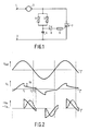
- Figure 1 shows a generally known circuit arrangement for controlling a load, constructed as a motor in this case.
- the AC power supply for the motor 3, for example, the mains voltage is presented to the power supply terminals 1 and 2.
- a terminal of the motor is connected to the mains terminal 1, whilst the other terminal is connected to a controlled rectifier circuit, in this case a triac 7, and is connected to a resistor section comprising a trimming potentiometer 4 and a control potentiometer 5.
- the two potentiometers 4 and 5 are parallel arranged.
- a capacitor 6 the other terminal of which is connected to the other power supply terminal 2 is arranged in series with this parallel arrangement.
- a diac 8 supplying the control current for the control input of the triac 7 via a current limiting resistor 9 is connected to the junction point of the parallel arrangement of the resistors 4 and 5 and the capacitor 6.
- Figure 2 shows the waveform of the power supply voltage U net at the terminals 1 and 2.
- Figure 2b shows the waveform of the voltage U c across the capacitor 6.
- Figure 2c shows the waveform of the current I m through the motor and the waveform of the voltage U m across the motor.
- V p voltage drop
- V p voltage at the junction point between capacitor 6 and the two resistors 4 and 5
- V p voltage at the junction point between capacitor 6 and the two resistors 4 and 5
- V p voltage at the junction point between capacitor 6 and the two resistors 4 and 5
- V p voltage at the junction point between capacitor 6 and the two resistors 4 and 5
- V p voltage at the junction point between capacitor 6 and the two resistors 4 and 5
- V p the voltage at the junction point between capacitor 6 and the two resistors 4 and 5 will decrease by V p , which becomes manifest in the waveform of the voltage U c across the capacitor 6, Figure 2b.
- this capacitor voltage will be reduced stepwise by V p .
- the diac 8 breaks down so that a current starts to flow through the control input of the triac 7 which thereby becomes conducting.
- the now conducting triac 7 has a substantially negligible resistance and its result is that, considered electronically, the capacitor 6 is placed across the parallel arrangement of the resistors 4 and 5 and will now be discharged across these resistors.
- U c U t1 (1-e -t/RC ) wherein: U t1 is the voltage across the capacitor at the instant t1, c is the capacitance of capacitor 6 and R is the resistance of the parallel resistors 4 and 5.
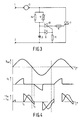
- Figure 3 shows a modified circuit arrangement which does not require any control.
- the components which are also present in the circuit arrangement of Figure 1 have the same reference numerals.
- the ignition current for the triac 7 is not supplied via the diac 8 and the resistor 9, but via a further triac whose control terminal is fed by the diac 8.
- This triac 10 then controls the control terminal of the triac 7 via the current limiting resistor 9.
- the trimming potentiometer 4 of Figure 1 is replaced by a fixed resistor 14 in this circuit arrangement.
- Figure 4a shows the waveform of the power supply voltage U net .
- Figure 4b shows the waveform of the voltage U across the capacitor 6.
- Figure 4c shows the waveform of the current I through the motor 3 and the voltage U c across the motor 3.
- the capacitor 6 is charged via the parallel resistors 5 and 14 until the breakdown voltage of the diac 8 has been reached at the instant t4. Due to the diac 8 becoming conducting the triac 10 will be rendered conducting and in its turn it supplies the control current for rendering the triac 7 conducting via the resistor 9.
- a resistor 11 between the control input of the triac 10 and the power supply terminal 2. This resistor is shown in a broken line in Figure 3.
- the resistor 9 does not play an essential role in the operation of the circuit arrangement and may be dispensed with in many cases without any problem.
Landscapes
- Engineering & Computer Science (AREA)
- Power Engineering (AREA)
- Power Conversion In General (AREA)
- Control Of Ac Motors In General (AREA)
Applications Claiming Priority (2)
| Application Number | Priority Date | Filing Date | Title |
|---|---|---|---|
| NL8702645 | 1987-11-05 | ||
| NL8702645 | 1987-11-05 |
Publications (1)
| Publication Number | Publication Date |
|---|---|
| EP0315273A1 true EP0315273A1 (fr) | 1989-05-10 |
Family
ID=19850871
Family Applications (1)
| Application Number | Title | Priority Date | Filing Date |
|---|---|---|---|
| EP88202440A Ceased EP0315273A1 (fr) | 1987-11-05 | 1988-11-01 | Circuit servant au réglage du courant alternatif par une charge |
Country Status (5)
| Country | Link |
|---|---|
| US (1) | US4914327A (fr) |
| EP (1) | EP0315273A1 (fr) |
| JP (1) | JPH01152954A (fr) |
| KR (1) | KR890009091A (fr) |
| DK (1) | DK610088A (fr) |
Cited By (3)
| Publication number | Priority date | Publication date | Assignee | Title |
|---|---|---|---|---|
| FR2819102A1 (fr) * | 2000-12-29 | 2002-07-05 | St Microelectronics Sa | Commutateur electronique bidirectionnel bistable a commande par impulsions |
| WO2003005555A1 (fr) * | 2001-07-05 | 2003-01-16 | Diehl Ako Stiftung & Co. Kg | Commande de regime pour un moteur universel a fluctuation d'intensite reduite |
| EP2154774A1 (fr) | 2008-08-12 | 2010-02-17 | ABB Oy | Procédé de contrôle d'un redresseur dans un mode de diode et circuit pour le contrôle |
Families Citing this family (8)
| Publication number | Priority date | Publication date | Assignee | Title |
|---|---|---|---|---|
| US5247230A (en) * | 1992-06-02 | 1993-09-21 | Lucerne Products, Inc. | Unilateral diac for motor speed control |
| US5363534A (en) * | 1992-06-19 | 1994-11-15 | U.S. Philips Corporation | Vacuum cleaner and suction tube for use with a vacuum cleaner |
| US5619081A (en) * | 1994-01-18 | 1997-04-08 | Leviton Manufacturing Co., Inc. | Asymmetrical AC trigger simulation |
| US5512810A (en) * | 1994-05-27 | 1996-04-30 | Eaton Corporation | Variable speed control for a hand-held electric power tool |
| US6226830B1 (en) | 1997-08-20 | 2001-05-08 | Philips Electronics North America Corp. | Vacuum cleaner with obstacle avoidance |
| US6188214B1 (en) * | 2000-02-18 | 2001-02-13 | Pass & Seymour, Inc. | Phase control switch with reduced heat dissipating RFI inductor |
| US7728564B2 (en) * | 2005-06-06 | 2010-06-01 | Lutron Electronics Co., Inc. | Power supply for a load control device |
| CA2620958C (fr) * | 2005-06-06 | 2012-04-24 | Lutron Electronics Co., Inc. | Alimentation de dispositif de controle de charge |
Citations (3)
| Publication number | Priority date | Publication date | Assignee | Title |
|---|---|---|---|---|
| BE641816A (fr) * | ||||
| FR1390166A (fr) * | 1962-12-29 | 1965-02-26 | Texas Instruments Inc | Circuit de commande pour un moteur série |
| NL7003842A (fr) * | 1970-03-18 | 1971-09-21 |
Family Cites Families (6)
| Publication number | Priority date | Publication date | Assignee | Title |
|---|---|---|---|---|
| US3484623A (en) * | 1966-04-13 | 1969-12-16 | Hunt Electronics Co | Power control circuit using bistable switching device |
| US3619656A (en) * | 1970-02-27 | 1971-11-09 | Motorola Inc | Bilateral voltage responsive switch |
| US3729651A (en) * | 1971-04-07 | 1973-04-24 | Ecc Corp | Voltage regulator |
| US3798470A (en) * | 1972-12-15 | 1974-03-19 | Gte Automatic Electric Lab Inc | Selective d.c. isolation circuit |
| US4069446A (en) * | 1974-11-30 | 1978-01-17 | Sanwa Chemical Co., Ltd. | Speed control means for AC motor |
| US4353025A (en) * | 1980-12-08 | 1982-10-05 | Hybrinetics, Inc. | Phase controlled voltage reducing circuit having line voltage compensation |
-
1988
- 1988-11-01 EP EP88202440A patent/EP0315273A1/fr not_active Ceased
- 1988-11-01 US US07/265,658 patent/US4914327A/en not_active Expired - Fee Related
- 1988-11-02 KR KR1019880014358A patent/KR890009091A/ko not_active Withdrawn
- 1988-11-02 DK DK610088A patent/DK610088A/da not_active Application Discontinuation
- 1988-11-02 JP JP63276331A patent/JPH01152954A/ja active Pending
Patent Citations (3)
| Publication number | Priority date | Publication date | Assignee | Title |
|---|---|---|---|---|
| BE641816A (fr) * | ||||
| FR1390166A (fr) * | 1962-12-29 | 1965-02-26 | Texas Instruments Inc | Circuit de commande pour un moteur série |
| NL7003842A (fr) * | 1970-03-18 | 1971-09-21 |
Non-Patent Citations (1)
| Title |
|---|
| PATENT ABSTRACTS OF JAPAN vol. 10, no. 263 (E-435) 2319 09 September 1986, & JP-A-61 88789 (MATSUSHITA ELECTRIC IND. CO. LTD) 07 May 1986, * |
Cited By (6)
| Publication number | Priority date | Publication date | Assignee | Title |
|---|---|---|---|---|
| FR2819102A1 (fr) * | 2000-12-29 | 2002-07-05 | St Microelectronics Sa | Commutateur electronique bidirectionnel bistable a commande par impulsions |
| WO2002054496A1 (fr) * | 2000-12-29 | 2002-07-11 | Stmicroelectronics S.A. | Commutateur electronique bidirectionnel bistable a commande par impulsions |
| WO2003005555A1 (fr) * | 2001-07-05 | 2003-01-16 | Diehl Ako Stiftung & Co. Kg | Commande de regime pour un moteur universel a fluctuation d'intensite reduite |
| US6854299B2 (en) | 2001-07-05 | 2005-02-15 | Diehl Ako Stiftung & Co. Kg | Rotary speed control for a universal motor, in particular for a washing machine drive |
| EP2154774A1 (fr) | 2008-08-12 | 2010-02-17 | ABB Oy | Procédé de contrôle d'un redresseur dans un mode de diode et circuit pour le contrôle |
| US7888986B2 (en) | 2008-08-12 | 2011-02-15 | Abb Oy | Method of controlling a rectifying bridge in a diode mode and a circuit for the control |
Also Published As
| Publication number | Publication date |
|---|---|
| KR890009091A (ko) | 1989-07-15 |
| JPH01152954A (ja) | 1989-06-15 |
| DK610088D0 (da) | 1988-11-02 |
| US4914327A (en) | 1990-04-03 |
| DK610088A (da) | 1989-05-06 |
Similar Documents
| Publication | Publication Date | Title |
|---|---|---|
| EP0188886A1 (fr) | Appareil de chauffage | |
| US8193744B2 (en) | Method and apparatus for quiet fan speed control | |
| US5479086A (en) | Process and device for reducing the inrush current when powering aninductive load | |
| US7397225B2 (en) | Apparatus for controlling the power of an AC voltage supplying an electrical consumer by phase control and method for reducing harmonics | |
| MXPA06014428A (es) | Aparatos y metodos para regular el suministro de energia electrica. | |
| US4914327A (en) | Circuit arrangement for controlling the alternating current through a load | |
| JPS5894017A (ja) | 制御装置 | |
| GB1601880A (en) | Control circuit for periodically supplying current to a load circuit | |
| EP0184659B1 (fr) | Appareil de multiplexage pour circuits commandés en phase | |
| US5652825A (en) | Power supply for low-voltage DC motor | |
| US4449054A (en) | Electronic circuit for controlling the supply voltage of electromagnets, electric motors, resistors, in single- and three-phase systems | |
| US4134038A (en) | Speed control for a universal electric motor | |
| AU2003260408B2 (en) | Device for controlling power by phase control, and method for reducing harmonic waves | |
| US5949158A (en) | Method and arrangement for controlling the output of electrical consumers connected to an AC line voltage | |
| EP0351821B1 (fr) | Appareil pour la commande d'un moteur triphasé à courant alternatif, en particulier un moteur à cage | |
| US4504777A (en) | Control circuit for holding constant the operating voltage of an electric load | |
| US7936576B2 (en) | Power controller | |
| US5463307A (en) | High efficiency, low voltage adapter apparatus and method | |
| US6933476B2 (en) | Heating unit with temperature sensor | |
| KR19980701559A (ko) | 직렬 모터의 속도 제어 장치(a device for control of the speed of a series motor) | |
| EP0147490A1 (fr) | Dispositif d'entrée pour une alimentation | |
| KR940003232B1 (ko) | 전자레인지의 자동전압 절환장치 | |
| JPS5927179B2 (ja) | 電源の突入電流制限回路 | |
| JPS59178994A (ja) | 直流モ−タ附勢装置 | |
| KR910004079Y1 (ko) | 모터의 정전력 공급장치 |
Legal Events
| Date | Code | Title | Description |
|---|---|---|---|
| PUAI | Public reference made under article 153(3) epc to a published international application that has entered the european phase |
Free format text: ORIGINAL CODE: 0009012 |
|
| AK | Designated contracting states |
Kind code of ref document: A1 Designated state(s): DE ES FR GB NL SE |
|
| 17P | Request for examination filed |
Effective date: 19891108 |
|
| 17Q | First examination report despatched |
Effective date: 19910826 |
|
| STAA | Information on the status of an ep patent application or granted ep patent |
Free format text: STATUS: THE APPLICATION HAS BEEN REFUSED |
|
| 18R | Application refused |
Effective date: 19920220 |