EP0315329B1 - Eprouvette de la pression pneumatique - Google Patents
Eprouvette de la pression pneumatique Download PDFInfo
- Publication number
- EP0315329B1 EP0315329B1 EP88309439A EP88309439A EP0315329B1 EP 0315329 B1 EP0315329 B1 EP 0315329B1 EP 88309439 A EP88309439 A EP 88309439A EP 88309439 A EP88309439 A EP 88309439A EP 0315329 B1 EP0315329 B1 EP 0315329B1
- Authority
- EP
- European Patent Office
- Prior art keywords
- pressure
- probe
- pneumatic pressure
- chamber
- hollow shaft
- Prior art date
- Legal status (The legal status is an assumption and is not a legal conclusion. Google has not performed a legal analysis and makes no representation as to the accuracy of the status listed.)
- Expired - Lifetime
Links
- 239000000523 sample Substances 0.000 title claims description 65
- 239000012528 membrane Substances 0.000 claims description 18
- 238000004891 communication Methods 0.000 claims description 12
- 238000013022 venting Methods 0.000 claims description 11
- 210000000981 epithelium Anatomy 0.000 claims description 9
- 230000001681 protective effect Effects 0.000 claims description 8
- 210000000056 organ Anatomy 0.000 claims description 7
- 230000002093 peripheral effect Effects 0.000 claims description 4
- 230000004410 intraocular pressure Effects 0.000 description 42
- 210000003128 head Anatomy 0.000 description 20
- 210000004087 cornea Anatomy 0.000 description 8
- 239000012530 fluid Substances 0.000 description 8
- 238000005259 measurement Methods 0.000 description 7
- 210000003038 endothelium Anatomy 0.000 description 5
- 230000010412 perfusion Effects 0.000 description 4
- 241000283973 Oryctolagus cuniculus Species 0.000 description 3
- 230000004872 arterial blood pressure Effects 0.000 description 3
- 238000009530 blood pressure measurement Methods 0.000 description 3
- 238000007599 discharging Methods 0.000 description 3
- 238000011160 research Methods 0.000 description 3
- 229910000906 Bronze Inorganic materials 0.000 description 2
- 241000282326 Felis catus Species 0.000 description 2
- 239000010974 bronze Substances 0.000 description 2
- 238000011088 calibration curve Methods 0.000 description 2
- KUNSUQLRTQLHQQ-UHFFFAOYSA-N copper tin Chemical compound [Cu].[Sn] KUNSUQLRTQLHQQ-UHFFFAOYSA-N 0.000 description 2
- 230000001419 dependent effect Effects 0.000 description 2
- 238000013461 design Methods 0.000 description 2
- 230000000694 effects Effects 0.000 description 2
- 230000008030 elimination Effects 0.000 description 2
- 238000003379 elimination reaction Methods 0.000 description 2
- 238000000034 method Methods 0.000 description 2
- 230000037361 pathway Effects 0.000 description 2
- 241001465754 Metazoa Species 0.000 description 1
- 239000004809 Teflon Substances 0.000 description 1
- 229920006362 Teflon® Polymers 0.000 description 1
- 230000003321 amplification Effects 0.000 description 1
- 210000002159 anterior chamber Anatomy 0.000 description 1
- 238000013459 approach Methods 0.000 description 1
- 210000004204 blood vessel Anatomy 0.000 description 1
- 210000001124 body fluid Anatomy 0.000 description 1
- 239000010839 body fluid Substances 0.000 description 1
- 210000001715 carotid artery Anatomy 0.000 description 1
- 210000004004 carotid artery internal Anatomy 0.000 description 1
- 238000006243 chemical reaction Methods 0.000 description 1
- 210000000744 eyelid Anatomy 0.000 description 1
- 150000008282 halocarbons Chemical class 0.000 description 1
- 238000010348 incorporation Methods 0.000 description 1
- 230000002452 interceptive effect Effects 0.000 description 1
- 238000012544 monitoring process Methods 0.000 description 1
- 230000003472 neutralizing effect Effects 0.000 description 1
- 238000003199 nucleic acid amplification method Methods 0.000 description 1
- 210000001636 ophthalmic artery Anatomy 0.000 description 1
- 230000010355 oscillation Effects 0.000 description 1
- 229920000642 polymer Polymers 0.000 description 1
- 229920000260 silastic Polymers 0.000 description 1
- 239000007787 solid Substances 0.000 description 1
- 230000004873 systolic arterial blood pressure Effects 0.000 description 1
Images



Classifications
-
- A—HUMAN NECESSITIES
- A61—MEDICAL OR VETERINARY SCIENCE; HYGIENE
- A61B—DIAGNOSIS; SURGERY; IDENTIFICATION
- A61B3/00—Apparatus for testing the eyes; Instruments for examining the eyes
- A61B3/10—Objective types, i.e. instruments for examining the eyes independent of the patients' perceptions or reactions
- A61B3/16—Objective types, i.e. instruments for examining the eyes independent of the patients' perceptions or reactions for measuring intraocular pressure, e.g. tonometers
Definitions
- This invention relates to devices for use in measuring physiological fluid pressure and in particular to pneumatic pressure probes.
- Prior art pneumatic pressure probes also known as tonometers, usually are applanation or force balance pressure sensing devices.
- Applanation type pressure sensors operate by measuring the force required to flatten a predetermined area on the surface encasing the fluid.
- U.S. Patent No. 3,714,819 to Webb A representative prior art tonometer is shown in U.S. Patent No. 3,714,819 to Webb.
- This device uses a pneumatically driven piston provided with a sensing tip which is operated by the gas driving the piston.
- a force balance is maintained between the organ to which the device is applied, e.g., an eye, and the sensing tip of the device itself. That is, the force with which a membrane on the sensing tip is pushed against the eye is equal to the force with which a gas within the device pushes against the piston that drives the sensing tip.
- FIGURES 1(a) to 1(d) show the pressure recorded internally in a human eye during the application of a pressure sensor.
- FIGURES 1(a) and 1(c) show that the prior art gas bearing pneumatic probe increased the intraocular pressure by 6 mmHg, i.e., from a set IOP of 15 mmHg to 21 mmHg during the period the probe was applied to the eye.
- FIGURES 1(b) and 1(d) show that the present probe increased the set IOP of 15 mmHg by less than 1 mmHg.
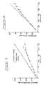
- FIGURE 2(a) shows that in rabbits with an average IOP of 20 mmHg the prior art probe caused the pressure to increase to more than 30 mmHg.
- the increased intraocular pressure caused a throttling effect on the gas flow and as a consequence the venting of gas directly to the atmosphere increased proportionately.
- the magnitude of this loss, and as a consequence the size of the non-linearity of the calibration curve is critically dependent on the geometry of the vent pathway. In practice this is difficult to control and as a consequence the curvilinearity of probes may differ significantly.
- the present invention is a pneumatic pressure probe that provides a relatively rapid and accurate measurement of a fluid pressure within a organ, such as an eye or a blood vessel, without distorting the organ itself.
- the probe utilizes a sensor head that contacts the organ without applying thereto an error introducing force.
- the pneumatic pressure probe of the present invention includes a hollow handle defining a pressure chamber and a forshortenable hollow shaft slidably received within the handle.
- the proximal end of the hollow shaft is in communication with the pressure chamber but is not influenced by the pressure developed within that chamber.
- a sensor head is mounted on the distal end of the hollow shaft and defines a contact face as well as a cavity that provides a venting chamber which extends to and terminates in a sensing aperture in the contact face.
- the sensing aperture can be covered by a membrane.
- the hollow shaft extends into the cavity and terminates in a thrust nozzle that is substantially coplanar with a plane defined by the contact face.
- the contact face is placed in contact with the membrane surrounding an organ such as the eye but without distorting it.
- the thrust of the gas discharging from the thrust nozzle applies a limited force to the area of the epithelium of the membrane adjacent to the thrust nozzle without distorting the shape of the endothelium.
- no force is applied to the body fluid the pressure of which is to be measured.
- FIGURES 1(b) and 1(c) in which the intraocular pressure of human eyes were recorded during the application of the probe to eyes with an intraocular pressure of 15 mmHg. It will be observed that the probe caused the intraocular pressures to increase by less than 1 mmHg.
- the shaft allows the sensor head to move relative to the handle, however, thereby neutralizing the effect of hand movements of the operator.
- the patient can be in a standing, sitting or supine position during the fluid pressure measurement.
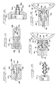
- the pneumatic pressure probe 12 includes a hollow elongated handle 14, a hollow, elongated and foreshortenable shaft 24 having a proximal end 26 (FIGURE 8) extending into the handle 14 and a sensor head 34 attached to the distal end 32 of the shaft 24.
- the handle 14 defines therewithin a pressure chamber 16.
- a pressurizing gas passageway 18 is in communication with the pressure chamber 16 and adapted for operable association with a conventional pressurized gas source (not shown) for pressurizing the pressure chamber 16.
- a throttle means 22 in the pressurizing gas passageway 18 throttles the flow of gas to create a pressure gradient between the gas source and the pressure chamber 16. This pressure gradient insures a constant flow of gas which is minimally influenced by the pressure developed in the pressure chamber 16 as the instrument is used. Alternatively, the throttle means 22 may be located elsewhere between the gas source and the pressure chamber or it may be eliminated.
- a gas exit passageway 20 is in communication with the pressure chamber 16 and is adapted for communication with a conventional pressure transducer (not shown) for measuring the pressure within chamber 16.
- the hollow handle 14 also defines a dampening chamber 28.
- Shaft 24 extends through this dampening chamber.
- shaft 24 is forshortenable with respect to the handle 14 by being slidably received within the handle, thus allowing the contact face 36 to be kept in relatively stable contact with the body membrane notwithstanding gross movements of the hand of the operator.
- the mechanism by which the shaft 24 is foreshortened is not critical as long as it does not affect the pressure of the fluid to be measured.
- Proximal end 26 of the shaft 24 is in communication with the pressure chamber 16. There is substantially no gas leakage between the pressure chamber 16 and dampening chamber 28.
- a movement limiting means 30 affixed to the shaft 24 limits the movement of the sensor head 34 relative to the handle 14.
- a preferred movement limiting means 30 is a disk having a relatively low coefficient of friction (e.g., a disk made from a solid halogenated hydrocarbon polymer such as that commercially available under the designation "Teflon"). Because the disk is located in the dampening chamber 28, no force is applied thereto by the flowing gas, and thus the disk merely limits the movement of the sensor head 34 but does not transmit any force to the sensor head.
- a disk having a relatively low coefficient of friction e.g., a disk made from a solid halogenated hydrocarbon polymer such as that commercially available under the designation "Teflon"
- the sensor head 34 defines a substantially planar contact face 36 and a cavity that provides a venting chamber 44 which extends to and terminates in a sensing aperture 38 in contact face 36.
- Peripheral vents 42 are provided in sensor head 34 and are in communication with the venting chamber 44.
- the thrust nozzle 40 is a continuation of hollow shaft 24 and extends through the venting chamber 44.
- the thrust nozzle 40 is preferably coplanar with the contact surface 36 but may be slightly recessed from the plane defined by the contact face 36. This recess can be up to about 0.005 inches (0.013 cm).
- a protective membrane 70 such as a smooth silastic, usually about 5 to 10 microns thick, fits over the contact face 36 without tension.
- the protective membrane 70 is held in position by a membrane retaining means shown here as a retaining clip 48 which reversibly cooperates with the peripheral groove 46. This clip may form part of the membrane.
- the venting chamber 44 is in communication with the pressure chamber 16 through the hollow shaft 24 and its terminal thrust nozzle 40.
- FIGURE 10 shows an alternative embodiment of a sensor head 134 that does not utilize a protective membrane.
- the thrust nozzle 140 is substantially coplanar with a plane defined by the contact face 136.
- FIGURE 11 An alternative embodiment of a handle 214 is shown in FIGURE 11.
- the handle 214 only defines a pressure chamber 216 but not a dampening chamber.
- the pressure chamber 216 In communication with the pressure chamber 216 is the proximal end 226 of the foreshortenable shaft 224, slidably received within bore 225 of handle 214.
- FIGURES 12 and 13 show alternative embodiments of the hollow, elongated and forshortenable shaft 24 as shown in FIGURES 7-9.
- shaft 324 is comprised of interactive elements 352, 354 and 356 which cooperate so as to allow shaft 324 to reversibly telescope.
- the shaft 424 has a reversibly collapsible section 460 which allows foreshortening.
- FIGURE 14 schematically shows the present sensor head while measuring intraocular pressure (IOP) within an eye.
- IOP intraocular pressure
- the total gas flow from the aforedescribed pressure chamber is directed through the hollow shaft 24 to the sensor head 34 where the gas discharges from the thrust nozzle 40.
- the contact face 36 covered by membrane 70, is placed against the epithelium 64 of the cornea 62 of an eye.
- the thrust from thrust nozzle 40 applies a force to the area of the epithelium 64 adjacent the thrust nozzle 40.
- the radius of curvature of the region of the epithelium 64 circumscribed by the sensing aperture 38 is somewhat reduced, but the radius of curvature of the endothelium 66 remains substantially unchanged.
- the epithelium 64 exerts a reaction force on the gas discharging from the thrust nozzle 40. This force, in turn, generates a pressure in the pressure chamber such as chamber 16 in FIGURE 8.
- the pressure transducer attached to the gas exit passageway measures the pressure within the pressure chamber. The gas exits the sensor head 34 via vents 42.
- the pressure measured by the transducer in the pressure chamber corresponds substantially to the instantaneous pressure within the eye. Accordingly, pressure fluctuations within the eye can be readily monitored and recorded. In this manner the eye of the patient can be utilized as a "built-in" transducer suitable for monitoring not only IOP, but the patient's circulatory system as well.
- the rate of mass flow through the thrust nozzle 40 is adjusted to provide a thrust or force against the cornea 62 of the eye sufficient to reduce the radius of curvature of the epithelium 64 of the cornea 62 without flattening the endothelium 66.
- the present configuration of the thrust nozzle 40 and the venting chamber 44 also permits an amplification of the detected instantaneous fluctuations.
- the gain is a function of the area of the thrust nozzle 40 making contact with the cornea.
- a gain of about 2 to about 3 is utilized for IOP measurement.
- the "gain" refers to the mechanical gain expressed as a ratio of the IOP to that of the pressure within the measuring device.
- the sensor head 134 When the sensor head 134 is used as shown in FIGURE 15, that is, without a protective membrane, the associated gas passageway, the pressure chamber, the hollow shaft 124, the vents 142, the gas exit passageway 120 and the pressure transducer operate as previously described.
- the thrust of the gas discharging from the thrust nozzle 40 somewhat reduces the curvature of the epithelium 64 adjacent to the thrust nozzle 40 but does not affect the curvature of the endothelium 66. Only the area of the epithelium adjacent to the thrust nozzle 40 is affected.
- the present pressure probe is particularly useful for determining the IOP and the oscillation of the IOP, i.e., is the ocular pressure amplitude (PA), for diagnostic purposes.
- PA ocular pressure amplitude
- the condition of the ocular perfusion pressure is also assessable from the IOP and PA.
- the patient may be situated in any comfortable position during the pressure measurement.
- the PA of the patient's eyes are recorded at normal IOP's.
- the IOP is then raised to equal one half the brachial systolic arterial pressure.
- Convenient ways to raise the IOP include applying suction from a vacuum system to the eye or applying digital pressure to the upper and lower eyelids.
- the PA's are recorded at the raised IOP.
- the PA values are symmetrical in pairs of eyes under identical conditions and the PA's at the raised IOP are approximately 50% of the initial value.
- the ophthalmic arterial pressure and ocular perfusion pressure is reflected as a decrease in the PA. If only one eye is affected, the PA readings will not be symmetrical in pairs of eyes under identical conditions. At the increased IOP, the PA of the affected eye is greatly less than its initial value and may go to zero. A PA of zero indicates that the ophthalmic arterial pressure is less than the IOP. This procedure allows rapid assessment of the ocular perfusion pressure which is an indication of the condition of the carotid and ophthalmic arteries.
- the accuracy of the present pneumatic pressure probe is dependent on maintaining an almost constant flow of gas through the sensor head.
- This linearity has not been found to exist in an air bearing pressure probe as can be seen from FIGURE 4. In the latter, a deviation from linearity occurs with increasing levels of pressure within the eye.
Landscapes
- Life Sciences & Earth Sciences (AREA)
- Health & Medical Sciences (AREA)
- Medical Informatics (AREA)
- Biophysics (AREA)
- Ophthalmology & Optometry (AREA)
- Engineering & Computer Science (AREA)
- Biomedical Technology (AREA)
- Heart & Thoracic Surgery (AREA)
- Physics & Mathematics (AREA)
- Molecular Biology (AREA)
- Surgery (AREA)
- Animal Behavior & Ethology (AREA)
- General Health & Medical Sciences (AREA)
- Public Health (AREA)
- Veterinary Medicine (AREA)
- Eye Examination Apparatus (AREA)
- Measuring And Recording Apparatus For Diagnosis (AREA)
Claims (13)
- Sonde de pression pneumatique (12) qui comprend :
un manche creux (14) de forme allongée, définissant intérieurement une chambre de pression (16), un passage (18) de gaz de mise sous pression communiquant avec la chambre de pression et adapté pour coopérer avec une source de gaz sous pression pour mettre la chambre de pression sous pression, et un passage de sortie de gaz (20) communiquant avec la chambre de pression et adapté pour communiquer avec un moyen transducteur de pression ;
un tige creuse (24) de forme allongée et raccourcissable, logée dans ledit manche et ayant une extrémité distale qui déborde au-delà dudit manche ; et
une tête de capteur (34) montée sur l'extrémité distale de ladite tige creuse et définissant une face de contact (36) sensiblement plane destinée à être posée sur l'épithélium d'un organe, une cavité qui forme une chambre à évent (44) qui s'étend jusqu'à une ouverture de détection (38) prévue dans la face de contact et se termine par cette ouverture, et un moyen d'évent périphérique (42) communiquant avec ladite cavité ;
ladite extrémité distale de la tige étant engagée dans ladite cavité sur une, distance fixe et se terminant par une buse de poussée (40) qui est sensiblement dans un plan défini par ladite face de contact mais qui ne se prolonge pas au-delà de ce plan ; et
ladite chambre de pression communiquant avec ladite cavité par ladite tige creuse,
caractérisée en ce que l'extrémité proximale (26) de ladite tige creuse est engagée dans ladite chambre de pression (16), l'agencement étant tel que ladite tige creuse ne transmette pas de force résultant de la pression développée dans la chambre de pression. - Sonde de pression pneumatique selon la revendication 1, dans laquelle ladite buse de poussée (40) est en retrait d'une distance pouvant aller jusqu'à environ 0,13 cm (0,005 pouce) par rapport au plan défini par la face de contact (36).
- Sonde de pression pneumatique selon la revendication 1 ou la revendication 2, dans laquelle ladite tête de capteur (34) comprend aussi un moyen (48) de retenue de membrane protectrice destinée à retenir une membrane protectrice amovible (70) en position sur ladite face de contact (36).
- Sonde de pression pneumatique selon la revendication 3 dans laquelle ledit moyen (48) de retenue de membrane protectrice est défini par la tête de capteur (34) sous la forme d'une gorge périphérique (46) et ledit moyen de retenue de membrane protectrice comprend en outre une agrafe de retenue (48) qui coopère avec ladite gorge de façon amovible.
- Sonde de pression pneumatique selon une quelconque des revendications précédentes, dans laquelle ladite tige creuse (24) peut coulisser dans ledit manche (14).
- Sonde de pression pneumatique selon la revendication 5, comprenant en outre un moyen (30) de limitation du mouvement servant à limiter le mouvement de ladite tête de capteur (34) par rapport audit manche (14).
- Sonde de pression pneumatique selon une quelconque des revendications 1 à 5, dans laquelle ledit manche (14) définit en outre intérieurement une chambre d'amortissement (28), ladite extrémité proximale (26) de ladite tige creuse (24) traversant ladite chambre d'amortissement et pénétrant dans ladite chambre de pression (16).
- Sonde de pression pneumatique selon la revendication 7, comprenant en outre un moyen (30) de limitation du mouvement associé à ladite tige (24) pour limiter le mouvement de ladite tête de capteur (34) par rapport audit manche (14).
- Sonde de pression pneumatique selon la revendication 8, dans lequel ledit moyen (30) de limitation du mouvement est placé dans ladite chambre d'amortissement (28).
- Sonde de pression pneumatique selon la revendication 6 ou la revendication 8, dans laquelle ledit moyen (30) de limitation du mouvement est un disque fixé à ladite tige creuse (24).
- Sonde de pression pneumatique selon une quelconque des revendications précédentes, dans laquelle ladite tige creuse (24) est une tige creuse télescopique.
- Sonde de pression pneumatique selon une quelconque des revendications 1 à 10, dans laquelle ladite tige creuse (24) est une tige creuse rétractable de façon réversible.
- Sonde de pression pneumatique selon une quelconque des revendications précédentes, dans laquelle ladite voie de passage (18) du gaz de mise sous pression comprend un moyen d'étranglement (22) servant à créer un gradient de pression entre ladite source de gaz et ladite chambre de pression (16).
Applications Claiming Priority (2)
| Application Number | Priority Date | Filing Date | Title |
|---|---|---|---|
| US07/117,235 US4883056A (en) | 1987-11-05 | 1987-11-05 | Pneumatic pressure probe |
| US117235 | 1987-11-05 |
Publications (3)
| Publication Number | Publication Date |
|---|---|
| EP0315329A2 EP0315329A2 (fr) | 1989-05-10 |
| EP0315329A3 EP0315329A3 (en) | 1990-06-13 |
| EP0315329B1 true EP0315329B1 (fr) | 1994-09-21 |
Family
ID=22371705
Family Applications (1)
| Application Number | Title | Priority Date | Filing Date |
|---|---|---|---|
| EP88309439A Expired - Lifetime EP0315329B1 (fr) | 1987-11-05 | 1988-10-10 | Eprouvette de la pression pneumatique |
Country Status (5)
| Country | Link |
|---|---|
| US (1) | US4883056A (fr) |
| EP (1) | EP0315329B1 (fr) |
| JP (1) | JP2720992B2 (fr) |
| CN (1) | CN1017963B (fr) |
| DE (1) | DE3851605D1 (fr) |
Families Citing this family (14)
| Publication number | Priority date | Publication date | Assignee | Title |
|---|---|---|---|---|
| GB2295460B (en) * | 1994-11-26 | 1998-04-29 | O B F Labs | Improvements in and relating to a pneumatic pressure probe |
| USD387162S (en) * | 1995-10-24 | 1997-12-02 | Cds Technologies, L.L.C. | Tonometer probe |
| US6730073B2 (en) * | 2000-10-20 | 2004-05-04 | Medtronic, Inc. | Method of performing a lasik procedure and tonometer system for use therewith |
| US20050137473A1 (en) * | 2002-06-17 | 2005-06-23 | Antti Kontiola | Apparatus for measuring intraocular pressure |
| US7537137B2 (en) | 2002-10-10 | 2009-05-26 | Csp Technologies, Inc. | Resealable moisture tight container assembly for strips and the like having a lip snap seal |
| WO2005039379A2 (fr) * | 2003-10-24 | 2005-05-06 | Tonoguard Ltd. | Dispositif de mesure de la pression intra-oculaire |
| US7296487B2 (en) * | 2004-02-18 | 2007-11-20 | Curtiss Wright Controls, Inc. | Linkage and sensor assembly |
| FI119096B (fi) * | 2004-12-21 | 2008-07-31 | Tiolat Oy | Sovitelma silmänpainemittarissa |
| CN101940467A (zh) * | 2010-09-27 | 2011-01-12 | 崔浩 | 眼压测试仪的压力拾取装置 |
| JP2016034285A (ja) * | 2015-11-16 | 2016-03-17 | 株式会社Lsiメディエンス | 眼圧測定方法 |
| US12295656B2 (en) | 2016-02-25 | 2025-05-13 | Ocuflow, Inc. | Composite ocular blood flow analyzer |
| DE102018107621A1 (de) * | 2018-03-29 | 2019-10-02 | Imedos Systems GmbH | Vorrichtung und Verfahren zur Untersuchung der metabolischen Autoregulation |
| US11957413B2 (en) * | 2019-08-06 | 2024-04-16 | University of Pittsburgh—of the Commonwealth System of Higher Education | Solitary wave-based trans-lid tonometer |
| US11730366B2 (en) * | 2019-10-21 | 2023-08-22 | Ocuflow, Inc. | Pneumatic pressure probe |
Family Cites Families (8)
| Publication number | Priority date | Publication date | Assignee | Title |
|---|---|---|---|---|
| US1900285A (en) * | 1927-07-09 | 1933-03-07 | W I Huber Inc | Sphygmomanometer |
| US3099262A (en) * | 1962-06-21 | 1963-07-30 | Du Pont | Physiologic fluid pressure sensing head |
| US3272001A (en) * | 1963-12-16 | 1966-09-13 | Instr Corp Comp | Tonometer |
| US3349623A (en) * | 1965-06-09 | 1967-10-31 | Abex Corp | Fluid filled pressure transducer |
| US3628526A (en) * | 1969-04-14 | 1971-12-21 | Du Pont | Physiologic fluid pressure sensor head |
| US3703095A (en) * | 1970-03-10 | 1972-11-21 | Univ Johns Hopkins | Applanation tonometer |
| US3714819A (en) * | 1970-11-19 | 1973-02-06 | Block Engineering | Applanation tonometer comprising porous air bearing support for applanating piston |
| US4386611A (en) * | 1980-06-02 | 1983-06-07 | Warner Lambert Technologies, Inc. | Tonometer with improved fluid discharged tube |
-
1987
- 1987-11-05 US US07/117,235 patent/US4883056A/en not_active Expired - Lifetime
-
1988
- 1988-10-10 EP EP88309439A patent/EP0315329B1/fr not_active Expired - Lifetime
- 1988-10-10 DE DE3851605T patent/DE3851605D1/de not_active Expired - Lifetime
- 1988-11-04 JP JP63279159A patent/JP2720992B2/ja not_active Expired - Fee Related
- 1988-11-05 CN CN88107691A patent/CN1017963B/zh not_active Expired
Also Published As
| Publication number | Publication date |
|---|---|
| EP0315329A3 (en) | 1990-06-13 |
| EP0315329A2 (fr) | 1989-05-10 |
| DE3851605D1 (de) | 1994-10-27 |
| CN1032900A (zh) | 1989-05-17 |
| US4883056A (en) | 1989-11-28 |
| JP2720992B2 (ja) | 1998-03-04 |
| CN1017963B (zh) | 1992-08-26 |
| JPH01280441A (ja) | 1989-11-10 |
Similar Documents
| Publication | Publication Date | Title |
|---|---|---|
| US3992926A (en) | Pressure measuring method and apparatus with digital readout | |
| US4883056A (en) | Pneumatic pressure probe | |
| US5165409A (en) | Tonometry apparatus | |
| US4951671A (en) | Tonometry apparatus | |
| Moses et al. | Evaluation of the basic validity and clinical usefulness of the Mackay-Marg tonometer | |
| US5094244A (en) | Apparatus and process for determining systolic blood pressure, diastolic blood pressure, mean arterial blood pressure, pulse rate, pulse wave shape, respiratory pattern, and respiratory rate | |
| US20100152565A1 (en) | Non-invasive tonometer | |
| JPH09510372A (ja) | センサのインビボ・キャリブレーションを行なう装置及び方法 | |
| EP3419500B1 (fr) | Analyseur de flux sanguin oculaire composite | |
| Eklund et al. | An applanation resonator sensor for measuring intraocular pressure using combined continuous force and area measurement | |
| US5857969A (en) | Pneumatic pressure probe | |
| Moses et al. | The pneumatonograph: a laboratory study | |
| US6083161A (en) | Apparatus and method for improved intraocular pressure determination | |
| US3628526A (en) | Physiologic fluid pressure sensor head | |
| Stein et al. | Arterial tonometry for the atraumatic measurement of arterial blood pressure. | |
| US6394968B1 (en) | Trans-scleral method and apparatus for measuring intraocular pressure | |
| EP3071091B1 (fr) | Dispositif de détermination d'une pression intraoculaire d'un oeil | |
| Kanngiesser et al. | Simulation of dynamic contour tonometry compared to in vitro study revealing minimal influence of corneal radius and astigmatism. The theoretical foundations of dynamic contour tonometry | |
| JPS58113835A (ja) | 体腔内硬度測定用プローブ | |
| JP3838765B2 (ja) | 眼圧計 | |
| Hachol et al. | Ophthalmic tonometer with silicon micromachined structure | |
| Schneider et al. | Dynamic contour tonometry | |
| Neault et al. | Modification and calibration of the Bigliano—Webb Tonometer for improved accuracy of tonometry in rabbits | |
| LINNÉR et al. | APPLANATION TONOGRAPHY AT CONSTANT INTRAOCULAR PRESSURE: I. Basic considerations | |
| RU2070815C1 (ru) | Способ определения ригидности глаза |
Legal Events
| Date | Code | Title | Description |
|---|---|---|---|
| PUAI | Public reference made under article 153(3) epc to a published international application that has entered the european phase |
Free format text: ORIGINAL CODE: 0009012 |
|
| AK | Designated contracting states |
Kind code of ref document: A2 Designated state(s): BE DE FR GB |
|
| PUAL | Search report despatched |
Free format text: ORIGINAL CODE: 0009013 |
|
| AK | Designated contracting states |
Kind code of ref document: A3 Designated state(s): BE DE FR GB |
|
| 17P | Request for examination filed |
Effective date: 19901122 |
|
| 17Q | First examination report despatched |
Effective date: 19930303 |
|
| GRAA | (expected) grant |
Free format text: ORIGINAL CODE: 0009210 |
|
| AK | Designated contracting states |
Kind code of ref document: B1 Designated state(s): BE DE FR GB |
|
| PG25 | Lapsed in a contracting state [announced via postgrant information from national office to epo] |
Ref country code: FR Effective date: 19940921 Ref country code: BE Effective date: 19940921 |
|
| PGFP | Annual fee paid to national office [announced via postgrant information from national office to epo] |
Ref country code: GB Payment date: 19941012 Year of fee payment: 7 |
|
| REF | Corresponds to: |
Ref document number: 3851605 Country of ref document: DE Date of ref document: 19941027 |
|
| PG25 | Lapsed in a contracting state [announced via postgrant information from national office to epo] |
Ref country code: DE Effective date: 19941222 |
|
| EN | Fr: translation not filed | ||
| PLBE | No opposition filed within time limit |
Free format text: ORIGINAL CODE: 0009261 |
|
| STAA | Information on the status of an ep patent application or granted ep patent |
Free format text: STATUS: NO OPPOSITION FILED WITHIN TIME LIMIT |
|
| 26N | No opposition filed | ||
| PG25 | Lapsed in a contracting state [announced via postgrant information from national office to epo] |
Ref country code: GB Effective date: 19951010 |
|
| GBPC | Gb: european patent ceased through non-payment of renewal fee |
Effective date: 19951010 |