EP0315357B1 - Drehzahlmesser - Google Patents
Drehzahlmesser Download PDFInfo
- Publication number
- EP0315357B1 EP0315357B1 EP19880310031 EP88310031A EP0315357B1 EP 0315357 B1 EP0315357 B1 EP 0315357B1 EP 19880310031 EP19880310031 EP 19880310031 EP 88310031 A EP88310031 A EP 88310031A EP 0315357 B1 EP0315357 B1 EP 0315357B1
- Authority
- EP
- European Patent Office
- Prior art keywords
- signal
- time
- circuit
- varying
- battery
- Prior art date
- Legal status (The legal status is an assumption and is not a legal conclusion. Google has not performed a legal analysis and makes no representation as to the accuracy of the status listed.)
- Expired
Links
- 238000001914 filtration Methods 0.000 claims description 18
- 238000002485 combustion reaction Methods 0.000 claims description 9
- 238000000034 method Methods 0.000 claims description 9
- 230000001747 exhibiting effect Effects 0.000 claims 1
- 238000012545 processing Methods 0.000 description 18
- 238000010304 firing Methods 0.000 description 7
- 238000012360 testing method Methods 0.000 description 3
- 235000019504 cigarettes Nutrition 0.000 description 2
- 230000036039 immunity Effects 0.000 description 2
- 238000012935 Averaging Methods 0.000 description 1
- 230000005355 Hall effect Effects 0.000 description 1
- 230000003044 adaptive effect Effects 0.000 description 1
- 238000004378 air conditioning Methods 0.000 description 1
- 230000000903 blocking effect Effects 0.000 description 1
- 239000003990 capacitor Substances 0.000 description 1
- 238000001816 cooling Methods 0.000 description 1
- 238000010586 diagram Methods 0.000 description 1
- 230000009977 dual effect Effects 0.000 description 1
- 238000005516 engineering process Methods 0.000 description 1
- 238000011156 evaluation Methods 0.000 description 1
- 230000001939 inductive effect Effects 0.000 description 1
- 238000005259 measurement Methods 0.000 description 1
- 238000000691 measurement method Methods 0.000 description 1
- 239000000523 sample Substances 0.000 description 1
- 238000007619 statistical method Methods 0.000 description 1
- 239000002699 waste material Substances 0.000 description 1
Images
Classifications
-
- G—PHYSICS
- G01—MEASURING; TESTING
- G01P—MEASURING LINEAR OR ANGULAR SPEED, ACCELERATION, DECELERATION, OR SHOCK; INDICATING PRESENCE, ABSENCE, OR DIRECTION, OF MOVEMENT
- G01P3/00—Measuring linear or angular speed; Measuring differences of linear or angular speeds
- G01P3/42—Devices characterised by the use of electric or magnetic means
- G01P3/44—Devices characterised by the use of electric or magnetic means for measuring angular speed
- G01P3/48—Devices characterised by the use of electric or magnetic means for measuring angular speed by measuring frequency of generated current or voltage
- G01P3/481—Devices characterised by the use of electric or magnetic means for measuring angular speed by measuring frequency of generated current or voltage of pulse signals
Definitions
- the present invention relates to testing equipment for internal combustion engines.
- the present invention relates to a tachometer for determining the engine speed (RPM) of an internal combustion engine of a vehicle.
- tachometer (RPM) measurement methods have become a problem because it is impossible to connect engine speed transducers to some vehicles, and extremely difficult to connect transducers to others.
- DIS distributorless ignition system
- DIS systems have dual firing voltage on each spark plug wire, one for normal firing and the other for what is known as "waste firing”.
- the prior art secondary type transducers pick up both spark plug firings, and the measuring equipment must distinguish these signals in order to develop a proper tachometer reading.
- the secondary signals sensed by these prior art transducers are not considered to be as reliable as one would like, since spark plug condition and cross firing can create undesirable or unreliable information.
- US-A-3693073 discloses a device for testing internal combustion engines, comprising an averaging circuit which responds proportionally to the number of times that the breaker points of the engine's distributor open or close. The output of the circuit is, thus, an average value proportional to engine speed.
- a circuit for providing an output signal representative of the speed of an engine having an electrical ignition system connected to a battery comprising means for producing the output signal as a function of a selected signal related to the engine speed, is characterised in that the circuit also comprises means for deriving the selected signal from the battery, which signal is representative of a time-varying component of the output of the battery related to the engine speed.
- the present invention is a tachometer which produces a signal representative of engine speed of an internal combustion engine based upon signals derived from the battery which powers the ignition system of the internal combustion engine.
- the signal derived from the battery contains many different components produced by the various electrical systems connected to the vehicle battery.
- sources of signals appearing at the vehicle battery terminal include the primary switching current, alternator ripple, spark plug firing noise, injector opening pulses, radiator cooling fan, brush noise, electronic voltage regulator operations, air conditioning system noise, and others.
- any system in the vehicle that uses substantial amounts of electrical power will contribute a component or components to the electrical signal which is appearing across the vehicle battery terminals.
- the invention comprises a circuit for providing an output signal representative of speed of an internal combustion engine of the type having an electrical ignition system connected to a battery, the circuit comprising: means for deriving a battery signal representative of battery current flow having a plurality of time-varying components; means for selecting from the battery signal a selected time-varying component which is representative of engine speed; and means for producing the output signal as a function of the selected time-varying component.
- the signal from the vehicle battery is filtered and signal processed to separate the wanted signal (which represents operation of the ignition system) from the unwanted signals.
- the result of the filtering and signal processing is, in preferred embodiments, a pulse signal which has a frequency related to the speed of the engine.
- the first and more common signal component is produced by the primary switching current.
- a second signal component produced by short bursts of high frequency ringing can also be used to derive an output signal representative of engine RPM.
- the invention also extends to a method of measuring speed of an internal combustion engine of the type having an electrical ignition system connected to a battery, the method comprising: deriving from current flow of the battery a time-varying signal associated with operation of the electrical ignition system; and providing an output signal representative of engine speed as a function of the time-varying signal.
- deriving the time varying signal comprises: removing a DC component of a signal received from the battery; and filtering AC components of the signal received from the battery to derive the time-varying signal.
- the filtering comprises: removing the signal received from the battery signal components having frequencies outside a range associated with primary ignition current pulses.
- the filtering comprises: removing from the signal received from the battery signal components having frequencies outside a range associated, with ignition bursts.
- the tachometer includes a first signal processing path which separates the primary switching current signal component from the battery.
- a second current path separates the signal component representing short bursts of high frequency ringing which occur when spark plugs fire.
- Switching means select the signal path which produces the more reliable signal, the supplies that signal to pulse generating means (such as a one shot or monostable multivibrator) to produce the output pulse signal.
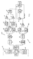
- FIG. 1 shows an electrical block diagram of a battery tachometer according to the present invention, as connected to a vehicle battery.
- tachometer 10 is connected to plus (+) and minus (-) terminals 12A and 12B, respectively, of vehicle battery 14. Also shown in the Figure are ignition system 16 of internal combustion engine 18, as well as other electrical systems 20 of vehicle 22. Battery 14 is the conventional DC battery used to provide electrical power for vehicle 22.
- Tachometer 10 makes electrical connection to terminals 12A and 12B of battery 14 either directly, or through a convenient connector, such as the cigarette lighter receptacle (not shown) of vehicle 22.
- Tachometer 10 includes DC block and hash filter circuit 24 which receives the signals from vehicle battery 14.
- the output of DC block and hash filter 24 is provided to two separate signal processing paths 26A and 26B.
- the outputs of signal processing paths 26A and 26B merge at A/B select switch 28.
- the output selected by switch 28 is provided to digital one shot 30, which produces an output pulse signal which is supplied to RPM converter and display 32.
- the output pulses from digital one shot 30 are produced at a frequency which is representative of RPM of the vehicle engine.
- RPM converter and display 32 converts the output pulses from digital one shot 30 to an RPM value, and displays that value either numerically or graphically.
- Signal processing circuit path 26A includes high pass filter 34, amplifier 36, fast peak detector 38, slow peak detector 40 and comparator 42. Circuit path 26A separates, from the vehicle battery signal, the component which represents short bursts of high frequency ringing which occurs when a spark plug fires.
- Signal processing circuit path 26B includes amplifier 44, high pass filter 46, low pass filter 48, band pass filter 50, HI/LO RPM select switch 52, positive peak detector 54, negative peak detector 56, comparators 58 and 60, and flipflop 62.
- the purpose of signal processing circuit path 26B is to separate the signal component which represents the current provided to the primary of the ignition system 18. These current pulses have approximately a fifty percent duty cycle, and circuit path 26B filters the signal based on this approximate fifty percent duty cycle.
- DC block and hash filter 24 blocks the DC component of the battery signal from reaching either circuit path 26A or 26B.
- circuit 24 also provides some hash filtering. The purpose of this filtering is to eliminate some very high frequency signals which cannot be handled by the subsequent processing in signal paths 26A and 26B.
- high pass filter 34 is a 10 kHz high pass filter which attenuates signals other than the ignition bursts. These bursts are then amplified by amplifier 36 and provided to peak detectors 38 and 40.
- Fast peak detector 38 has an output which rises quickly to the peak value of its input and falls off quickly.
- Slow peak detector 40 has an output which rises more slowly toward the peak of the input and has a slow fall off. The outputs of peak detectors 38 and 40 are sent to comparator 42.
- the output of fast peak detector 38 rises faster than the output of slow peak detector 40, and comparator 42 outputs a pulse of a length equal to the time required by slow peak detector 40 to catch up with fast peak detector 38.
- the long fall-off time of slow peak detector 40 aids in preventing extraneous output pulses from comparator 42.
- Signal processing path 26B filters lower frequency signals, since it is looking for the primary switching current pulses.
- the signal from DC block and hash filter circuit 24 is first amplified by amplifier 44.
- 20 Hz high pass filter 46 is then used to attenuate signals which are lower than those produced by an idling engine.
- the filtered signal is then sent to filters 48 and 50.
- Low pass filter 48 is a 50 Hz low pass filter which together with high pass filter 46 covers the range (about 20 Hz to about 50 Hz) for idling four cycle (stroke) engines with four, six or eight cylinders.
- Band pass filter 50 is a band pass filter which covers the range (50-150 Hz) for revving engines.
- the outputs of filters 48 and 50 are provided to HI/LO RPM select switch 52.
- the selection of the filter 48 or 50 used to provide a signal to the subsequent components of signal processing path 26 is based upon feedback from RPM converter and display 32 by way of a high/low RPM signal, which controls the state of switch 52.
- switch 52 is changed so that the output of band pass filter 50 is used.
- switch 52 is changed back to low pass filter 48.
- Filters 48 and 50 have overlapping ranges, so that the signal will not be lost between filter ranges.
- the switching between ranges by RPM converter and display 32 and switch 52 preferably has a hysteresis band to prevent hunting.
- the selected signal from switch 52 is provided to positive peak detector 54 and negative peak detector 56.
- the signal is also fed to comparators 58 and 60 for comparison with the outputs of peak detectors 54 and 56, respectively.
- the outputs+ of peak detectors 54 and 56 are a fraction (preferably about one-half) of their respective peak signal points.
- Comparators 58 and 60 drive the reset and set inputs of flipflop 62, respectively. When the signal from filter 48 or filter 50 exceeds the fractional portion of the average positive signal peak as represented by the output of positive peak detector 54, flipflop 62 is reset. Similarly, when the signal from filter 48 or 50 is at a negative value less than the fractional average negative peaks represented by the output of negative peak detector 56, flipflop 62 is set.
- the output of flipflop 62 is usually a good representation of the firing rate of the engine.
- switch 28 is controlled by an operator based upon an evaluation of which signal processing path will be more effective. That determination may be made, for example, by the operator's familiarity with the particular vehicle and the type of signals which it produces.
- switch 28 is controlled by an A/B select signal which may be produced by other signal processing circuitry within RPM converter and display 32.
- the selection of state of the A/B select signal is based for example on a statistical analysis of the outputs of both signal paths 26A and 26B.
- RPM converter and display 32 preferably includes a digital computer such as a microcomputer.
- the output of switch 28 is provided to the input of digital one shot 30, which produces an output pulse of a precise time duration to RPM converter and display 32.
- the frequency of the output pulses of one shot 30 is controlled by the particular input signal from either signal processing path 26A or 26B.
- One shot 30 is preferably a digital device, because it provides a precise time duration for causing an interrupt, reading the counter, and resetting it to an initial value for measurement of time until the next pulse.
- the counter value can be corrected to compensate for the time of the one shot as it can be much more precise than an analog one shot. In other embodiments of the present invention, however, one shot 30 can be an analog rather than a digital device.
- the present invention is a tachometer which is reliable and which is easily connected to every vehicle because it merely requires access to the positive and negative terminals of the vehicle battery. This connection can be made either directly to the vehicle battery itself, or to other accessible points such as the cigarette lighter receptacle.
- tachometer 10 An important advantage of the tachometer of the present invention is its ability to operate with all levels of signals which are available on the battery terminals.
- tachometer 10 filters the various signals found on the battery terminals 12A and 12B and develops a usable triggering signal for making tachometer (RPM) readings.
- RPM tachometer
- Tachometer 10 overcomes the problems of making connections to new ignition systems which are devoid of test points for RPM readings. It also does not rely on secondary wire connections, since in some ignition systems these connections are either covered and not available, or are extremely difficult and of questionable reliability.
- the signal processing circuitry of tachometer 10 will also accept other sources of the input battery signal (which represents the flow of battery current).
- the input battery signal which represents the flow of battery current.
- Hall effect or inductive type current probes can be used to sense battery current flow at or near the battery.
- a current shunt connected in series with one of the battery terminals or a device for measuring voltage across the battery cable between vehicle ground and the (-) battery terminal can be used to supply the battery signal to battery tach 10 of the present invention.
- paths 26A and 26B can be implemented in a number of different ways, and with different technologies.
- programmable-type filters such as switched-capacitor or charge coupled device filters can be used to provide low pass, band pass and high pass filtering.
- the need for a separate HI/LO RPM switch 52 may be eliminated, and the low pass and band pass filters 48 and 50 can be embodied in a single variable characteristic filter.
- Another advantage of the present invention is its compatability with digital signal processing techniques. Except for DC block and hash filter 24, the remaining circuitry of battery tach 10 shown in the Figure can be implemented in either analog or digital circuitry. Digital signal processing techniques offer the further advantage of allowing more adaptive filtering and, in some cases, more complex filtering without a corresponding increase in hardware complexity or cost.
Landscapes
- Physics & Mathematics (AREA)
- General Physics & Mathematics (AREA)
- Combined Controls Of Internal Combustion Engines (AREA)
Claims (16)
- Schaltung zur Bildung eines Ausgangssignals, das die Drehzahl eines Motors mit einem mit einer Batterie verbundenen elektrischen Zündsystem darstellt, wobei die Schaltung Mittel zur Erzeugung des Ausgangssignals als Funktion eines zur Motordrehzahl in Beziehung stehenden ausgewählten Signals aufweist, dadurch gekennzeichnet, daß die Schaltung auch Mittel zum Ableiten des ausgewählten Signals von der Batterie aufweist, welches Signal für eine zeitlich veränderliche Komponente des Ausgangs der Batterie mit Bezug auf die Motordrehzahl repräsentativ ist.
- Schaltung nach Anspruch 1, wobei die Mittel zum Ableiten die zeitlich veränderliche Komponente aus den dem Betrieb des elektrischen Zündsystems zugeordneten Signalkomponenten auswählen.
- Schaltung nach Anspruch 2, wobei die Mittel zum Ableiten Mittel zum Ausfiltern der zeitlich veränderlichen Komponenten mit einer Frequenz außerhalb eines normalerweise Zündimpulsen zugeordneten Frequenzbereichs aufweisen, um eine für die Motordrehzahl repräsentative zweite zeitlich veränderliche Komponente auszuwählen, und wobei die Mittel zur Erzeugung des Ausgangssignals Mittel zum Auswählen der ersten oder der zweiten zeitlich veränderlichen Komponente einschließen.
- Schaltung nach Anspruch 2, wobei die Mittel zum Ableiten Mittel zum Ausfiltern der zeitlich veränderlichen Komponenten mit einer Frequenz außerhalb eines normalerweise Zündimpulsen zugeordneten Frequenzbereichs aufweisen, um eine für die Motordrehzahl repräsentative zweite zeitlich veränderliche Komponente auszuwählen.
- Schaltung nach Anspruch 4, wobei der Frequenzbereich größer als etwa 10 kHz ist.
- Schaltung nach Anspruch 4 oder 5, wobei die Mittel zur Erzeugung des Ausgangssignals erste und zweite Spitzenwertdetektormittel zum Erzeugen erster und zweiter Signale als eine Funktion von Spitzenwerten der zweiten zeitlich veränderlichen Komponente, wobei die ersten und zweiten Spitzenwertdetektormittel verschiedene Zeit-Antworten auf die zweite zeitlich veränderliche Komponente zeigen; und Komparatormittel zum Vergleichen der ersten und zweiten Signale zur Erzeugung des Ausgangssignals aufweisen.
- Schaltung nach Anspruch 1 oder 2, wobei die Mittel zum Ableiten Mittel zum Ausfiltern zeitlich veränderlicher Komponenten mit einer Frequenz außerhalb eines normalerweise primären Zündstromimpulsen zugeordneten Frequenzbereichs aufweisen, um eine für die Motordrehzahl repräsentative erste zeitlich veränderliche Komponente auszuwählen.
- Schaltung nach Anspruch 7, wobei die Filtermittel erste Filtermittel zum Ausfiltern von Frequenzen außerhalb eines den vom leerlaufenden Motor erzeugten primären Zündstromimpulsen zugeordneten ersten Bereichs und zweite Filtermittel zum Ausfiltern von Frequenzen außerhalb eines den vom beschleunigenden Motor erzeugten primären Zündimpulsen zugeordneten zweiten Bereichs aufweisen.
- Schaltung nach Anspruch 8, wobei der erste Bereich zwischen etwa 20 Hz und etwa 50 Hz liegt.
- Schaltung nach Anspruch 8 oder 9, wobei der zweite Bereich zwischen etwa 50 Hz und etwa 150 Hz liegt.
- Schaltung nach einem der Ansprüche 8 bis 10, die ferner Mittel zum Auswählen eines Signals von dem ersten oder dem zweiten Filtermittel als die für die Motorgeschwindigkeit repräsentative erste zeitlich veränderliche Komponente aufweist.
- Schaltung nach einem der Ansprüche 7 bis 11, wobei die Mittel zur Erzeugung des Ausgangssignals erste und zweite Spitzenwertdetektormittel zum Erzeugung erster und zweiter Spitzenwertdetektorsignale, welche eine Funktion der positiven und negativen Spitzenwerte der ersten zeitlich veränderlichen Komponente sind, und erste und zweite Komparatormittel zum vergleichen der ersten zeitlich veränderlichen Komponente mit dem ersten und zweiten Spitzenwertdetektorsignal zum Erzeugen eines ersten bzw. zweiten Komparatorsignals aufweisen, wobei der Ausgang aus dem ersten und zweiten Komparatorsignal gewonnen wird.
- Verfahren zum Messen der Drehzahl eines internen Verbrennungsmotors mit einem elektrischen, mit einer Batterie verbundenen Zündsystem, wobei das Verfahren das Ableiten eines zeitlich veränderlichen, dem Betrieb des elektrischen Zündsystems zugeordneten Signals vom Stromfluß der Batterie und das Liefern eines für die Motordrehzahl repräsentativen Ausgangssignals als eine Funktion des zeitlich veränderlichen Signals umfaßt.
- Verfahren nach Anspruch 13, wobei das Ableiten des zeitlich veränderlichen Signals das Entfernen einer Gleichstromkomponente eines von der Batterie empfangenen Signals und das Filtern der Wechselstromkomponenten des von der Quelle empfangenen Signals zum Ableiten des zeitlich veränderlichen Signals umfaßt.
- Verfahren nach Anspruch 14, wobei das Filtern das Entfernen der Komponenten des von der Batterie empfangenen Signals mit Frequenzen außerhalb eines den primären Zündstromimpulsen zugeordneten Bereichs umfaßt.
- Verfahren nach Anspruch 14, wobei das Filtern ein Entfernen der Komponenten des von dem Batteriesignal empfangenen Signals mit Frequenzen außerhalb eines den Zündimpulsen zugeordneten Bereichs umfaßt.
Applications Claiming Priority (2)
| Application Number | Priority Date | Filing Date | Title |
|---|---|---|---|
| US11663487A | 1987-11-03 | 1987-11-03 | |
| US116634 | 1998-07-16 |
Publications (2)
| Publication Number | Publication Date |
|---|---|
| EP0315357A1 EP0315357A1 (de) | 1989-05-10 |
| EP0315357B1 true EP0315357B1 (de) | 1992-05-06 |
Family
ID=22368349
Family Applications (1)
| Application Number | Title | Priority Date | Filing Date |
|---|---|---|---|
| EP19880310031 Expired EP0315357B1 (de) | 1987-11-03 | 1988-10-25 | Drehzahlmesser |
Country Status (3)
| Country | Link |
|---|---|
| EP (1) | EP0315357B1 (de) |
| CA (1) | CA1320357C (de) |
| DE (1) | DE3870810D1 (de) |
Cited By (1)
| Publication number | Priority date | Publication date | Assignee | Title |
|---|---|---|---|---|
| DE4431720C1 (de) * | 1994-09-06 | 1996-02-29 | Sun Electric Deutschland Gmbh | Verfahren und Vorrichtung zur Bestimmung der Drehzahl von Verbrennungskraftmaschinen |
Families Citing this family (9)
| Publication number | Priority date | Publication date | Assignee | Title |
|---|---|---|---|---|
| DE3923532A1 (de) * | 1989-07-15 | 1991-01-24 | Bosch Gmbh Robert | Verfahren zur drehzahlermittlung einer brennkraftmaschine |
| DE4025218A1 (de) * | 1990-08-09 | 1992-02-20 | Bosch Gmbh Robert | Vorrichtung zur drehzahlermittlung einer brennkraftmaschine |
| DE19547832C2 (de) * | 1995-12-21 | 2002-04-18 | Grundig Ag | Verfahren und Schaltungsanordnung zur Drehzahlermittlung eines mit einem Generator gekoppelten Verbrennungsmotors |
| DE19715643A1 (de) * | 1997-04-15 | 1998-10-22 | Bosch Gmbh Robert | Verfahren zur Ermittlung der Drehzahl einer Brennkraftmaschine |
| DE19720698A1 (de) * | 1997-05-16 | 1998-11-19 | Bosch Gmbh Robert | Anordnung zur Drehzahlmessung an einer Brennkraftmaschine |
| DE19825023C2 (de) * | 1998-06-04 | 2001-02-08 | Siemens Ag | Verfahren und Anordnung zum Bestimmen der Motordrehzahl eines Kraftfahrzeugs |
| DE102004055018A1 (de) * | 2004-11-15 | 2006-05-24 | E-Lead Electronic Co., Ltd. | Fahrzeuggeschwindigkeits-Detektions-Vorrichtung |
| DE102009045410B4 (de) | 2009-10-07 | 2021-05-06 | Robert Bosch Gmbh | Verfahren und Vorrichtung zur Drehzahlbestimmung |
| CN103645338A (zh) * | 2013-12-14 | 2014-03-19 | 广东志高空调有限公司 | 一种空调pg测速仪 |
Family Cites Families (2)
| Publication number | Priority date | Publication date | Assignee | Title |
|---|---|---|---|---|
| US3693073A (en) * | 1970-10-23 | 1972-09-19 | Orbit Lab Inc | Multiple function testing device for internal combustion engine |
| US3942113A (en) * | 1974-06-05 | 1976-03-02 | Exxon Research And Engineering Company | Remote engine speed indicator system |
-
1988
- 1988-10-25 DE DE8888310031T patent/DE3870810D1/de not_active Expired - Lifetime
- 1988-10-25 EP EP19880310031 patent/EP0315357B1/de not_active Expired
- 1988-11-02 CA CA000581978A patent/CA1320357C/en not_active Expired - Lifetime
Cited By (2)
| Publication number | Priority date | Publication date | Assignee | Title |
|---|---|---|---|---|
| DE4431720C1 (de) * | 1994-09-06 | 1996-02-29 | Sun Electric Deutschland Gmbh | Verfahren und Vorrichtung zur Bestimmung der Drehzahl von Verbrennungskraftmaschinen |
| DE4431720C2 (de) * | 1994-09-06 | 2001-03-15 | Sun Electric Deutschland Gmbh | Verfahren und Vorrichtung zur Bestimmung der Drehzahl von Verbrennungskraftmaschinen |
Also Published As
| Publication number | Publication date |
|---|---|
| CA1320357C (en) | 1993-07-20 |
| DE3870810D1 (de) | 1992-06-11 |
| EP0315357A1 (de) | 1989-05-10 |
Similar Documents
| Publication | Publication Date | Title |
|---|---|---|
| US5004979A (en) | Battery tach | |
| US4684896A (en) | Testing method for ignition systems of internal combustion engines in motor vehicles | |
| US4444172A (en) | Internal combustion engine knock sensing system | |
| US6868369B2 (en) | Tachometer | |
| US4111035A (en) | Engine knock signal generating apparatus with noise channel inhibiting feedback | |
| EP0277468B1 (de) | Verfahren und Gerät zur Feststellung und Anzeige von Zündungsanomalien beim Betrieb von Zündsystemen von Verbrennungsmaschinen, insbesondere für mit einem Katalysator ausgestattete Motorfahrzeuge | |
| US6123057A (en) | Arrangement and process for communication between an ignition module and control unit in a combustion engine's ignition system | |
| US4862093A (en) | Method and an arrangement for the detection of ionizing current in the ignition system of an internal combustion engine including engine start sequence detection | |
| EP0315357B1 (de) | Drehzahlmesser | |
| US4333334A (en) | Knocking discrimination apparatus | |
| JPH02503814A (ja) | スパーク点火方式内燃エンジンの燃焼監視の方法と装置 | |
| US5524480A (en) | Method of determining the rough engine run of an internal combustion engine | |
| US4312214A (en) | Knock detector for internal combustion engine | |
| US4522185A (en) | Switching electronic ignition | |
| US4539957A (en) | Ignition timing control system for internal combustion engines | |
| US5866808A (en) | Apparatus for detecting condition of burning in internal combustion engine | |
| EP0344349B1 (de) | Einrichtung zur Erkennung von Zündaussetzern bei fremdgezündeten Brennkraftmaschinen | |
| US6467448B2 (en) | Remote engine starter system | |
| US5821754A (en) | Ignition system for an internal combustion engine | |
| JP3212601B2 (ja) | 信号検出装置 | |
| US5327867A (en) | Misfire-detecting system for internal combustion engines | |
| US5107817A (en) | Method of associating ignition signals with a reference cylinder | |
| GB2262812A (en) | Misfire-detecting system for internal combustion engines | |
| US4724702A (en) | LPP sensor interface circuit | |
| US4601197A (en) | Peak combustion pressure timing detector for internal combustion engine |
Legal Events
| Date | Code | Title | Description |
|---|---|---|---|
| PUAI | Public reference made under article 153(3) epc to a published international application that has entered the european phase |
Free format text: ORIGINAL CODE: 0009012 |
|
| AK | Designated contracting states |
Kind code of ref document: A1 Designated state(s): DE FR GB IT |
|
| 17P | Request for examination filed |
Effective date: 19891107 |
|
| 17Q | First examination report despatched |
Effective date: 19910124 |
|
| GRAA | (expected) grant |
Free format text: ORIGINAL CODE: 0009210 |
|
| AK | Designated contracting states |
Kind code of ref document: B1 Designated state(s): DE FR GB IT |
|
| REF | Corresponds to: |
Ref document number: 3870810 Country of ref document: DE Date of ref document: 19920611 |
|
| ET | Fr: translation filed | ||
| PLBE | No opposition filed within time limit |
Free format text: ORIGINAL CODE: 0009261 |
|
| STAA | Information on the status of an ep patent application or granted ep patent |
Free format text: STATUS: NO OPPOSITION FILED WITHIN TIME LIMIT |
|
| 26N | No opposition filed | ||
| ITPR | It: changes in ownership of a european patent |
Owner name: CESSIONE;SPX CORPORATION |
|
| REG | Reference to a national code |
Ref country code: FR Ref legal event code: TP |
|
| REG | Reference to a national code |
Ref country code: GB Ref legal event code: 732E |
|
| REG | Reference to a national code |
Ref country code: GB Ref legal event code: IF02 |
|
| PGFP | Annual fee paid to national office [announced via postgrant information from national office to epo] |
Ref country code: FR Payment date: 20031020 Year of fee payment: 16 |
|
| PGFP | Annual fee paid to national office [announced via postgrant information from national office to epo] |
Ref country code: GB Payment date: 20031022 Year of fee payment: 16 |
|
| PG25 | Lapsed in a contracting state [announced via postgrant information from national office to epo] |
Ref country code: GB Free format text: LAPSE BECAUSE OF NON-PAYMENT OF DUE FEES Effective date: 20041025 |
|
| GBPC | Gb: european patent ceased through non-payment of renewal fee |
Effective date: 20041025 |
|
| PG25 | Lapsed in a contracting state [announced via postgrant information from national office to epo] |
Ref country code: FR Free format text: LAPSE BECAUSE OF NON-PAYMENT OF DUE FEES Effective date: 20050630 |
|
| REG | Reference to a national code |
Ref country code: FR Ref legal event code: ST |
|
| PG25 | Lapsed in a contracting state [announced via postgrant information from national office to epo] |
Ref country code: IT Free format text: LAPSE BECAUSE OF NON-PAYMENT OF DUE FEES;WARNING: LAPSES OF ITALIAN PATENTS WITH EFFECTIVE DATE BEFORE 2007 MAY HAVE OCCURRED AT ANY TIME BEFORE 2007. THE CORRECT EFFECTIVE DATE MAY BE DIFFERENT FROM THE ONE RECORDED. Effective date: 20051025 |
|
| PGFP | Annual fee paid to national office [announced via postgrant information from national office to epo] |
Ref country code: DE Payment date: 20061130 Year of fee payment: 19 |
|
| PG25 | Lapsed in a contracting state [announced via postgrant information from national office to epo] |
Ref country code: DE Free format text: LAPSE BECAUSE OF NON-PAYMENT OF DUE FEES Effective date: 20080501 |