EP0315520B1 - Appareil d'éclairage à tubes fluorescents - Google Patents
Appareil d'éclairage à tubes fluorescents Download PDFInfo
- Publication number
- EP0315520B1 EP0315520B1 EP88402743A EP88402743A EP0315520B1 EP 0315520 B1 EP0315520 B1 EP 0315520B1 EP 88402743 A EP88402743 A EP 88402743A EP 88402743 A EP88402743 A EP 88402743A EP 0315520 B1 EP0315520 B1 EP 0315520B1
- Authority
- EP
- European Patent Office
- Prior art keywords
- trough
- fitting according
- longitudinal
- fitting
- snapping
- Prior art date
- Legal status (The legal status is an assumption and is not a legal conclusion. Google has not performed a legal analysis and makes no representation as to the accuracy of the status listed.)
- Expired - Lifetime
Links
- 239000004033 plastic Substances 0.000 claims description 5
- 229920003023 plastic Polymers 0.000 claims description 5
- 239000000463 material Substances 0.000 claims description 3
- 239000012815 thermoplastic material Substances 0.000 claims description 3
- 230000001413 cellular effect Effects 0.000 claims description 2
- 208000031968 Cadaver Diseases 0.000 description 8
- 241000287107 Passer Species 0.000 description 1
- 239000004793 Polystyrene Substances 0.000 description 1
- 230000006978 adaptation Effects 0.000 description 1
- 230000000903 blocking effect Effects 0.000 description 1
- 238000010276 construction Methods 0.000 description 1
- 230000001419 dependent effect Effects 0.000 description 1
- 230000004907 flux Effects 0.000 description 1
- 210000004907 gland Anatomy 0.000 description 1
- 238000000034 method Methods 0.000 description 1
- 239000004417 polycarbonate Substances 0.000 description 1
- 229920000515 polycarbonate Polymers 0.000 description 1
- 229920002223 polystyrene Polymers 0.000 description 1
- 238000003825 pressing Methods 0.000 description 1
- 238000007789 sealing Methods 0.000 description 1
- 230000035939 shock Effects 0.000 description 1
- 239000000725 suspension Substances 0.000 description 1
- 229920001169 thermoplastic Polymers 0.000 description 1
- 239000004416 thermosoftening plastic Substances 0.000 description 1
Images

Classifications
-
- F—MECHANICAL ENGINEERING; LIGHTING; HEATING; WEAPONS; BLASTING
- F21—LIGHTING
- F21S—NON-PORTABLE LIGHTING DEVICES; SYSTEMS THEREOF; VEHICLE LIGHTING DEVICES SPECIALLY ADAPTED FOR VEHICLE EXTERIORS
- F21S8/00—Lighting devices intended for fixed installation
- F21S8/04—Lighting devices intended for fixed installation intended only for mounting on a ceiling or the like overhead structures
-
- F—MECHANICAL ENGINEERING; LIGHTING; HEATING; WEAPONS; BLASTING
- F21—LIGHTING
- F21V—FUNCTIONAL FEATURES OR DETAILS OF LIGHTING DEVICES OR SYSTEMS THEREOF; STRUCTURAL COMBINATIONS OF LIGHTING DEVICES WITH OTHER ARTICLES, NOT OTHERWISE PROVIDED FOR
- F21V15/00—Protecting lighting devices from damage
- F21V15/01—Housings, e.g. material or assembling of housing parts
- F21V15/013—Housings, e.g. material or assembling of housing parts the housing being an extrusion
-
- F—MECHANICAL ENGINEERING; LIGHTING; HEATING; WEAPONS; BLASTING
- F21—LIGHTING
- F21V—FUNCTIONAL FEATURES OR DETAILS OF LIGHTING DEVICES OR SYSTEMS THEREOF; STRUCTURAL COMBINATIONS OF LIGHTING DEVICES WITH OTHER ARTICLES, NOT OTHERWISE PROVIDED FOR
- F21V15/00—Protecting lighting devices from damage
- F21V15/01—Housings, e.g. material or assembling of housing parts
- F21V15/015—Devices for covering joints between adjacent lighting devices; End coverings
-
- F—MECHANICAL ENGINEERING; LIGHTING; HEATING; WEAPONS; BLASTING
- F21—LIGHTING
- F21V—FUNCTIONAL FEATURES OR DETAILS OF LIGHTING DEVICES OR SYSTEMS THEREOF; STRUCTURAL COMBINATIONS OF LIGHTING DEVICES WITH OTHER ARTICLES, NOT OTHERWISE PROVIDED FOR
- F21V17/00—Fastening of component parts of lighting devices, e.g. shades, globes, refractors, reflectors, filters, screens, grids or protective cages
- F21V17/10—Fastening of component parts of lighting devices, e.g. shades, globes, refractors, reflectors, filters, screens, grids or protective cages characterised by specific fastening means or way of fastening
- F21V17/16—Fastening of component parts of lighting devices, e.g. shades, globes, refractors, reflectors, filters, screens, grids or protective cages characterised by specific fastening means or way of fastening by deformation of parts; Snap action mounting
- F21V17/164—Fastening of component parts of lighting devices, e.g. shades, globes, refractors, reflectors, filters, screens, grids or protective cages characterised by specific fastening means or way of fastening by deformation of parts; Snap action mounting the parts being subjected to bending, e.g. snap joints
-
- F—MECHANICAL ENGINEERING; LIGHTING; HEATING; WEAPONS; BLASTING
- F21—LIGHTING
- F21V—FUNCTIONAL FEATURES OR DETAILS OF LIGHTING DEVICES OR SYSTEMS THEREOF; STRUCTURAL COMBINATIONS OF LIGHTING DEVICES WITH OTHER ARTICLES, NOT OTHERWISE PROVIDED FOR
- F21V21/00—Supporting, suspending, or attaching arrangements for lighting devices; Hand grips
- F21V21/02—Wall, ceiling, or floor bases; Fixing pendants or arms to the bases
-
- F—MECHANICAL ENGINEERING; LIGHTING; HEATING; WEAPONS; BLASTING
- F21—LIGHTING
- F21V—FUNCTIONAL FEATURES OR DETAILS OF LIGHTING DEVICES OR SYSTEMS THEREOF; STRUCTURAL COMBINATIONS OF LIGHTING DEVICES WITH OTHER ARTICLES, NOT OTHERWISE PROVIDED FOR
- F21V3/00—Globes; Bowls; Cover glasses
- F21V3/04—Globes; Bowls; Cover glasses characterised by materials, surface treatments or coatings
-
- F—MECHANICAL ENGINEERING; LIGHTING; HEATING; WEAPONS; BLASTING
- F21—LIGHTING
- F21V—FUNCTIONAL FEATURES OR DETAILS OF LIGHTING DEVICES OR SYSTEMS THEREOF; STRUCTURAL COMBINATIONS OF LIGHTING DEVICES WITH OTHER ARTICLES, NOT OTHERWISE PROVIDED FOR
- F21V31/00—Gas-tight or water-tight arrangements
- F21V31/005—Sealing arrangements therefor
-
- F—MECHANICAL ENGINEERING; LIGHTING; HEATING; WEAPONS; BLASTING
- F21—LIGHTING
- F21Y—INDEXING SCHEME ASSOCIATED WITH SUBCLASSES F21K, F21L, F21S and F21V, RELATING TO THE FORM OR THE KIND OF THE LIGHT SOURCES OR OF THE COLOUR OF THE LIGHT EMITTED
- F21Y2103/00—Elongate light sources, e.g. fluorescent tubes
-
- F—MECHANICAL ENGINEERING; LIGHTING; HEATING; WEAPONS; BLASTING
- F21—LIGHTING
- F21Y—INDEXING SCHEME ASSOCIATED WITH SUBCLASSES F21K, F21L, F21S and F21V, RELATING TO THE FORM OR THE KIND OF THE LIGHT SOURCES OR OF THE COLOUR OF THE LIGHT EMITTED
- F21Y2113/00—Combination of light sources
Definitions
- the invention relates to a fluorescent tube lighting fixture.
- the body and the basin are placed facing each other with the interposition of an annular seal. To ensure their assembly, there are locking hooks which are put in place when the lighting fixture is installed.
- German document DE-AS-1 054 173 describes a waterproof fluorescent tube lighting device with a strip or electric unit arranged inside, of the type comprising a plastic body and a transparent bowl made by cutting extruded profiles , two end caps in injected thermoplastic material, longitudinal seals between the body and the bowl and annular seals carried by the end caps.
- One of the objects of the invention is to propose a lighting apparatus of simple construction and easy assembly, not requiring the use of locking hooks.
- Another object of the invention is to provide a waterproof lighting device the length of which can be determined without being dependent on the dimensions of the molds.
- Yet another object of the invention is to propose, for this lighting device, a particularly practical method of attachment and easy adjustment.
- the subject of the invention is a waterproof fluorescent tube lighting device with a strip or electrical unit placed inside, of the type comprising a plastic body and a transparent bowl made by cutting off extruded profiles, two end caps made of material injected thermoplastic, longitudinal seals between the body and the bowl and annular seals carried by the end caps, characterized in that each side of the bowl has an outer edge capable of snapping into the body and an inner wall s 'pressing on a longitudinal seal, and in that each end piece has an inner wall supporting a transverse annular seal applying to the interior of the body and the bowl, said lighting fixture being made of so as to set up the body, the end caps, the strip and the tubes, and then fix the basin by snap-fastening.
- the waterproof lighting device essentially consists of a body 1, two end pieces 2, 3 and a basin 4.
- the body 1 is made of cellular plastic material. It is in the form of an extruded profile which is then cut to the desired length for each lighting device.
- the body 1 is provided with longitudinal cells 5 having the role of lightening it while retaining a certain rigidity.
- the body 1 carries two longitudinal ribs 6 and 7 bent, capable of cooperating with hooks 8, 9 of a fixing base 10.
- the hooks 8, 9 are carried by flexible arms so as to allow a suspension of the body 1 by simple click.
- the body 1 is presented as a flat-bottom channel 11 with two inclined sides 12 and 13. Each side is limited by an edge 14, 15, the section of which has two inverted concavities.
- the first concavity is turned towards the inside of the body 1. It is intended to receive a seal 16, linear.
- the second concavity is turned outwards, it is intended to receive a hooking rib 17 of the basin 4.
- the basin 4 is in extruded profile, with substantially the same general shape as the body 1.
- it is made of polystyrene for example, or of polycarbonate in order to improve its resistance to possible shocks.
- polystyrene for example, or of polycarbonate in order to improve its resistance to possible shocks.
- it has a prismatic structure.
- the outer edge 22 carries, in its lower part, the hooking rib 17 capable of snapping into the second concavity, facing outward, from the edge 14 of the body 1. It also carries, in the vicinity of its upper end, a second rib 23 capable of snapping onto the upper edge of the first concavity, turned towards the inside, of the edge 14 of the body 1.
- the upper end 24 of the outer edge 22 projects upwards, so as to allow a grip to release the two ribs 23 and 17 of the edge 14 of the body 1 when the bowl 4 has to be removed to replace the fluorescent tubes for example.
- the lighting device according to the invention is produced in a particularly simple and economical manner.
- the length of the body 1 and that of the basin 4 are determined, and the sections of corresponding profiles are removed.
- the body 1, the end pieces 2, 3 and the strip 33 are put in place.
- the body 1 and the end pieces 2, 3 are fixed by snap-fastening.
- the tubes 34, 35 are put in place and the basin is fixed by snap-fastening.
- the entire apparatus is then ready to be fixed on a base 10, by snapping on the ribs 6, 7 on the hooks 8, 9.
- One or more bases being fixed to the ceiling, the lighting fixture is hung there. by snap-fastening.
- the device is adjusted in position by axial sliding relative to the bases.
- we ensure the blocking position of the device by means, for example, of a sliding locking part provided in each base.
- the transverse seal is ensured by the two annular seals 32 of the end pieces, and the longitudinal seal by the linear seals 16. As the bearing pressure on these seals is constant, the sealing is ensured under the best conditions.
Landscapes
- Engineering & Computer Science (AREA)
- General Engineering & Computer Science (AREA)
- Arrangement Of Elements, Cooling, Sealing, Or The Like Of Lighting Devices (AREA)
- Securing Globes, Refractors, Reflectors Or The Like (AREA)
Description
- L'invention concerne un appareil d'éclairage à tubes fluorescents.
- Dans les locaux où règne une ambiance humide, corrosive, ou fortement empoussiérée, il est connu de prévoir des appareils étanches d'éclairage à tubes fluorescents. Ces appareils comportent en général deux éléments principaux en cuvette : le corps et la vasque. Ces deux éléments sont en matière plastique injectée, la vasque étant translucide. Ils ont des dimensions bien définies : chaque modèle d'appareil d'éclairage correspondant à deux moules.
- Le corps et la vasque sont mis en place en regard l'un de l'autre avec interposition d'un joint annulaire d'étanchéité. Pour assurer leur assemblage, on dispose des crochets de verrouillage qui sont mis en place au moment de l'installation de l'appareil d'éclairage.
- Le document allemand DE-AS-1 054 173 décrit un appareil d'éclairage à tubes fluorescents étanche avec une réglette ou unité électrique disposée à l'intérieur, du type comportant un corps en matière plastique et une vasque transparente réalisés par tronçonnage de profilés extrudés, deux embouts en matériau thermoplastique injecté, des joints d'étanchéité longitudinale entre le corps et la vasque et des joints annulaires portés par les embouts.
- L'un des buts de l'invention est de proposer un appareil d'éclairage de construction simple et d'assemblage aisé, ne faisant pas appel à des crochets de verrouillage.
- Un autre but de l'invention est de prévoir un appareil étanche d'éclairage dont la longueur puisse être déterminée sans être tributaire des dimensions de moules.
- Un autre but encore de l'invention est de proposer, pour cet appareil d'éclairage, un mode de fixation particulièrement pratique et de réglage facile.
- L'invention a pour objet un appareil d'éclairage à tubes fluorescets étanche avec une réglette ou unité électrique disposée à l'intérieur, du type comportant un corps en matière plastique et une vasque transparente réalisés par tronçonnage de profilés extrudés, deux embouts en matériau thermoplastique injecté, des joints d'étanchéité longitudinale entre le corps et la vasque et des joints annulaires portés par les embouts, caractérisé en ce que chaque flanc de la vasque porte une bordure extérieure susceptible de s'encliqueter avec le corps et une paroi intérieure s'appuyant sur un joint d'étanchéité longitudinale, et en ce que chaque embout présente une paroi intérieure supportant un joint annulaire d'étanchéité transversale s'appliquant à l'intérieur du corps et de la vasque, ledit appareil d'éclairage étant réalisé de manière à mettre en place le corps, les embouts, la réglette et les tubes, et fixer ensuite la vasque par encliquetage.
- Selon d'autres caractéristiques de l'invention :
- le corps comporte un bord à deux concavités inversées dont la première tournée vers l'intérieur du corps reçoit le joint d'étanchéité longitudinale et la seconde, tournée vers l'extérieur, est destinée à recevoir une nervure d'accrochage ;
- la bordure extérieure de la vasque porte dans sa partie inférieure une nervure d'accrochage, une deuxième nervure susceptible de s'encliqueter sur un bord supérieur du bord du corps, et une extrémité supérieure saillante de préhension pour dégager les deux nervures du corps lorsqu'on enlève la vasque pour remplacer les tubes florescents ;
- le corps porte des nervures longitudinales susceptibles de coopérer avec des crochets d'une embase pour fixer l'appareil par encliquetage ;
- les nervures sont coudées et les crochets sont portés par des bras souples ;
- le corps est alvéolaire.
- un embout comporte une surface latérale qui présente des fentes pour laisser passer les nervures longitudinales du corps ;
- un joint annulaire s'applique à l'intérieur du corps qui se trouve tenu entre, d'une part, une surface latérale d'un embout à l'extérieur et, d'autre part, ledit joint à l'intérieur.
- A titre d'exemple, on a représenté au dessin annexé :
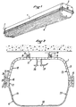
- Figure 1 : une vue perspective d' un appareil d'éclairage selon l'invention utilisé en plafonnier ;
- Figure 2 : une vue en coupe perpendiculaire à l'axe longitudinal de l'appareil d'éclairage de la figure 1, sans la réglette, ou unité électrique, et sans l'embout;
- Figure 3 : une vue, de l'intérieur, d'un embout de l'appareil d'éclairage de la figure 1 ;
- Figure 4 : une vue en coupe selon la figure 2 de l'appareil complet.
- En se reportant à la figure 1, on voit que l'appareil étanche d'éclairage selon l'invention se compose essentiellement d'un corps 1, de deux embouts 2, 3 et d'une vasque 4.
- Le corps 1 est en matériau plastique alvéolaire. Il se présente sous forme de profilé extrudé qui est ensuite tronçonné à la longueur voulue pour chaque appareil d'éclairage. Sur la figure 2, on voit que le corps 1 est muni d'alvéoles longitudinales 5 ayant pour rôle de l'alléger tout en lui conservant une certaine rigidité. A la partie supérieure, le corps 1 porte deux nervures longitudinales 6 et 7 coudées, susceptibles de coopérer avec des crochets 8, 9 d'une embase de fixation 10. Les crochets 8, 9 sont portés par des bras souples de façon à permettre une suspension du corps 1 par simple encliquetage.
- Le corps 1 se présente comme un canal à fond plat 11 avec deux flancs inclinés 12 et 13. Chaque flanc est limité par un bord 14, 15, dont la section présente deux concavités inversées. La première concavité est tournée vers l'intérieur du corps 1. Elle est destinée à recevoir un joint d'étanchéité 16, linéaire. La deuxième concavité est tournée vers l'extérieur, elle est destinée à recevoir une nervure d'accrochage 17 de la vasque 4.
- La vasque 4 est en profilé extrudé, avec sensiblement la même forme générale que le corps 1. Comme elle doit être transparente, elle est en polystyrène par exemple, ou en polycarbonate afin d'améliorer sa résistance aux chocs éventuels. Pour mieux maîtriser la répartition du flux lumineux émis par les tubes fluorescents disposés dans l'appareil d'éclairage, elle est à structure prismatique.
- Elle se présente comme un canal à fond plat 18, avec deux flancs inclinés 19, 20. Chaque flanc est prolongé par un bord intérieur 21 et une bordure extérieure 22, parallèles entre eux. Le bord intérieur est une paroi qui s'appuie sur le joint d'étanchéité 16, de façon à assurer l'étanchéité longitudinale de l'appareil entre le corps 1 et la vasque 4. La bordure extérieure 22 porte, dans sa partie inférieure, la nervure d'accrochage 17 susceptible de s'encliqueter dans la deuxième concavité, tournée vers l'extérieur, du bord 14 du corps 1. Elle porte également, au voisinage de son extrémité supérieure, une deuxième nervure 23 susceptible de s'encliqueter sur le bord supérieur de la première concavité, tournée vers l'intérieur, du bord 14 du corps 1. L'extrémité supérieure 24 de la bordure extérieure 22 est saillante vers le haut, de façon à permettre une préhension pour dégager les deux nervures 23 et 17 du bord 14 du corps 1 lorsqu'on doit enlever la vasque 4 pour remplacer les tubes fluorescents par exemple.
- Sur la figure 3, on voit la face intérieure de l'embout 3 de la figure 1. Cet embout 3 est en matériau thermoplastique injecté. Sa forme extérieure est définie pour son adaptation d'une part au corps 1, d'autre part à la vasque 4. La face d'extrémité 25 est munie d'un presse-étoupe 26 pour le passage du câble d'alimentation. La surface latérale 27 entoure le corps 1, c'est pourquoi elle présente deux fentes 28, 29, pour laisser passer les nervures longitudinales 6, 7. L'embout 3 présente une paroi intérieure 30 maintenue de l'intérieur par des nervures radiales 31 partielles. Cette paroi 30 sert d'appui et de support à un joint annulaire 32. Ainsi qu'on peut le voir sur la figure 4, ce joint 32 s'applique à l'intérieur du corps 1, qui se trouve tenu entre d'une part la surface latérale 27 à l'extérieur et d'autre part le joint 32 à l'intérieur. De même, le joint 32 s'applique sur l'intérieur de la vasque 4.
- Sur la figure 4, on voit que la réglette, ou unité électrique 33 est en place dans l'appareil. Elle est fixée aux supports en L représentés en 36 et 37 sur la figure 2, par des moyens non décrits pour ne pas surcharger le dessin. Dans cet exemple de réalisation, deux tubes fluorescents 34 et 35 ont été représentés.
- L'appareil d'éclairage selon l'invention est réalisé de manière particulièrement simple et économique. Tout d'abord, en fonction de la puissance électrique désirée, c'est-à-dire de la longueur des tubes fluorescents, on détermine la longueur du corps 1 et celle de la vasque 4, et on prélève les tronçons de profilés correspondants. On met en place le corps 1, les embouts 2, 3 et la réglette 33. On fixe le corps 1 et les embouts 2, 3 par encliquetage. On met en place les tubes 34, 35 et on fixe la vasque par encliquetage. L'ensemble de l'appareil est alors prêt à être fixé sur une embase 10, par encliquetage des nervures 6, 7 sur les crochets 8, 9. Une ou plusieurs embases étant fixées au plafond, on y accroche l'appareil d'éclairage par encliquetage. Ensuite on fait le réglage en position de l'appareil par coulissement axial par rapport aux embases. Enfin on assure le blocage en position de l'appareil au moyen par exemple d'une pièce de verrouillage coulissante prévue dans chaque embase.
- Dans l'appareil électrique selon l'invention, l' étanchéité transversale est assurée par les deux joints annulaires 32 des embouts, et l'étanchéité longitudinale par les joints linéaires 16. Comme la pression d'appui sur ces joints est constante, l'étanchéité est assurée dans les meilleures conditions.
Claims (8)
- Appareil d'éclairage à tubes fulorescents étanche avec une réglette ou unité électrique disposée à l'intérieur, du type comportant un corps en matière plastique et une vasque transparente réalisés par tronçonnage de profilés extrudés, de deux embouts en matériau thermoplastique injecté, des joints d'étanchéité longitudinale entre le corps et la vasque et des joints annulaires portés par les embouts, caractérisé en ce que chaque flanc de la vasque (4) porte une bordure extérieure (22) susceptible de s'encliqueter avec le corps (1) et une paroi intérieure (21) s'appuyant sur un joint d'étanchéité longitudinale (16), et en ce que chaque embout (2, 3) présente une paroi intérieure (30) supportant un joint annulaire (32) d'étanchéité transversale s'appliquant à l'intérieur du corps (1) et de la vasque (4), ledit appareil d'éclairage étant réalisé de manière à mettre en place le corps (1), les embouts (2,3), la réglette (33) et les tubes (34, 35), et fixer ensuite la vasque (4) par encliquetage.
- Appareil selon la revendication 1, caractérisé en ce que le corps (1) comporte un bord (14) à deux concavités inversées dont la première tournée vers l'intérieur du corps (1) reçoit le joint d'étanchéité longitudinale (16) et la seconde, tournée vers l'extérieur, est destinée à recevoir une nervure d'accrochage (17).
- Appareil selon la revendication 2, caractérisé en ce que la bordure extérieure (22) de la vasque (4) porte dans sa partie inférieure une nervure d'accrochage (17) , une deuxième nervure (23) susceptible de s'encliqueter sur un bord supérieur du bord (14) du corps (1), et une extrémité supérieure (24) saillante de préhension pour dégager les deux nervures (17, 23) du corps (1) lorsqu'on enlève la vasque (4) pour remplacer les tubes fluorescents.
- Appareil selon la revendication 1, caractérisé en ce que le corps (1) porte des nervures longitudinales (6, 7) susceptibles de coopérer avec des crochets (8, 9) d'une embase (10) pour fixer l'appareil par encliquetage.
- Appareil selon la revendication 4, caractérisé en ce que les nervures (6, 7) sont coudées et les crochets (8, 9) sont portés par des bras souples.
- Appareil selon la revendication 1, caractérisé en ce que le corps (1) est alvéolaire.
- Appareil selon la revendication 1, caractérisé en ce qu'un embout (2, 3) comporte une surface latérale (27), qui présente des fentes (28, 29) pour laisser passer les nervures longitudinales (6, 7) du corps (1).
- Appareil selon l'une des revendications 1 à 7, caractérisé en ce qu'un joint annulaire (32) s'applique à l'intérieur du corps (1) qui se trouve tenu entre, d'une part, une surface latérale (27) d'un embout (2 ou 3) à l'extérieur et, d'autre part, ledit joint (32) à l'intérieur.
Applications Claiming Priority (2)
| Application Number | Priority Date | Filing Date | Title |
|---|---|---|---|
| FR8715289 | 1987-11-04 | ||
| FR8715289A FR2622677B1 (fr) | 1987-11-04 | 1987-11-04 | Appareil etanche d'eclairage a tubes fluorescents |
Publications (2)
| Publication Number | Publication Date |
|---|---|
| EP0315520A1 EP0315520A1 (fr) | 1989-05-10 |
| EP0315520B1 true EP0315520B1 (fr) | 1996-01-17 |
Family
ID=9356476
Family Applications (1)
| Application Number | Title | Priority Date | Filing Date |
|---|---|---|---|
| EP88402743A Expired - Lifetime EP0315520B1 (fr) | 1987-11-04 | 1988-11-02 | Appareil d'éclairage à tubes fluorescents |
Country Status (4)
| Country | Link |
|---|---|
| EP (1) | EP0315520B1 (fr) |
| DE (1) | DE3854912T2 (fr) |
| ES (1) | ES2082754T3 (fr) |
| FR (1) | FR2622677B1 (fr) |
Cited By (1)
| Publication number | Priority date | Publication date | Assignee | Title |
|---|---|---|---|---|
| CN101761905B (zh) * | 2009-09-25 | 2011-10-05 | 海洋王照明科技股份有限公司 | 一种灯具及其密封结构 |
Families Citing this family (11)
| Publication number | Priority date | Publication date | Assignee | Title |
|---|---|---|---|---|
| GB8917055D0 (en) * | 1989-07-26 | 1989-09-13 | Light Years Ahead Ltd | Space lighting fitting |
| DE29502183U1 (de) * | 1995-02-10 | 1996-05-02 | Zumtobel Licht Gmbh, Dornbirn | Leuchte, insbesondere Feuchtraumleuchte, mit einem zweiteiligen geschlossenen Gehäuse |
| IT238854Y1 (it) * | 1995-06-19 | 2000-11-15 | Grusan Di Sandrin Giannino & C | Contenitore con coperchio di chiusura perfezionato |
| DE19620209A1 (de) * | 1996-05-20 | 1997-11-27 | Zumtobel Licht | Leuchte mit einem profilierten Basiskörper als Träger für wenigstens eine Lampe |
| GB2322441B (en) * | 1997-02-20 | 2000-09-13 | Illuma Lighting Ltd | Luminaires |
| AU2002218153A1 (en) * | 2000-12-05 | 2002-03-26 | Dki Plast A.S. | Lamp for mounting two or more fluorescent tubes |
| DE10131997A1 (de) * | 2001-07-02 | 2003-01-23 | Parol Leuchtenkomponenten Gmbh | Leuchte |
| DE102005058961A1 (de) | 2005-12-09 | 2007-06-14 | Zumtobel Lighting Gmbh | Leuchte mit einer in ihrem Hohlraum gehaltenen Tragplatte |
| EP1847769B1 (fr) * | 2006-04-22 | 2008-09-24 | Matthias Dipl.-Phys. Ing. Gimpel | Système d'ancrage, spécialement pour lampes |
| DE202011050244U1 (de) * | 2011-05-24 | 2012-08-29 | Zumtobel Lighting Gmbh | Leuchtmittel-Aufnahmekanal für eine Leuchte |
| WO2016087712A1 (fr) * | 2014-12-02 | 2016-06-09 | Ledil Oy | Système optique |
Family Cites Families (6)
| Publication number | Priority date | Publication date | Assignee | Title |
|---|---|---|---|---|
| DE1031424B (de) * | 1955-03-28 | 1958-06-04 | Dr Alfred Volk | Leuchte fuer Leuchtstofflampen |
| DE1214780B (de) * | 1958-11-19 | 1966-04-21 | Trilux Lenze Gmbh & Co Kg | Leuchte mit einem Leuchtengehaeuse mit einer Abdeckwanne aus Kunststoffglas |
| US4138716A (en) * | 1977-05-23 | 1979-02-06 | Arrem Plastics Inc. | Lighting fixture enclosure |
| DE8330300U1 (de) * | 1983-10-18 | 1984-04-12 | Semperlux Gmbh, 1000 Berlin | Leuchte mit begleitender linearer lichtquelle |
| CH658115A5 (fr) * | 1984-05-15 | 1986-10-15 | Youri Agabekov | Luminaire de forme allongee. |
| DE8513407U1 (de) * | 1985-05-07 | 1985-06-20 | Röhm GmbH, 6100 Darmstadt | Leichtes Bauelement |
-
1987
- 1987-11-04 FR FR8715289A patent/FR2622677B1/fr not_active Expired - Fee Related
-
1988
- 1988-11-02 ES ES88402743T patent/ES2082754T3/es not_active Expired - Lifetime
- 1988-11-02 EP EP88402743A patent/EP0315520B1/fr not_active Expired - Lifetime
- 1988-11-02 DE DE3854912T patent/DE3854912T2/de not_active Expired - Fee Related
Cited By (1)
| Publication number | Priority date | Publication date | Assignee | Title |
|---|---|---|---|---|
| CN101761905B (zh) * | 2009-09-25 | 2011-10-05 | 海洋王照明科技股份有限公司 | 一种灯具及其密封结构 |
Also Published As
| Publication number | Publication date |
|---|---|
| DE3854912T2 (de) | 1996-09-12 |
| EP0315520A1 (fr) | 1989-05-10 |
| ES2082754T3 (es) | 1996-04-01 |
| FR2622677A1 (fr) | 1989-05-05 |
| FR2622677B1 (fr) | 1991-12-13 |
| DE3854912D1 (de) | 1996-02-29 |
Similar Documents
| Publication | Publication Date | Title |
|---|---|---|
| EP0315520B1 (fr) | Appareil d'éclairage à tubes fluorescents | |
| FR2636308A1 (fr) | Couvercle obturateur en matiere plastique, notamment pour obturer un orifice pratique dans un support | |
| EP0944101A1 (fr) | Dispositif passe-barre et traversée électrique de paroi | |
| EP1260763B1 (fr) | Ensemble de montage d'un spot auto-portant sur un plafond tendu | |
| EP0653825A1 (fr) | Dispositif de traversée étanche à membrane souple et opercule jetable | |
| WO2004003395A2 (fr) | Dispositif pour fixer un objet sur une tige verticale | |
| EP1052454B1 (fr) | Luminaire d'intérieur/industriel | |
| FR2710790A1 (fr) | Dispositif de traversée étanche. | |
| FR2721093A1 (fr) | Luminaire, notamment pour l'éclairage public ou industriel, comportant un corps de réflecteur et un dispositif porte-douille de source lumineuse amovible par rapport à ce premier. | |
| EP1336696A1 (fr) | Dispositif d'accrochage pour appareil d'éclairage suspendu | |
| FR2518465A1 (fr) | Toit ouvrant de vehicule | |
| FR2993304A1 (fr) | Dispositif de montage d'un panneau vitre dans une menuiserie | |
| EP1164676A1 (fr) | Dispositif de montage d'un appareil électrique sur un conduit de câblage | |
| FR2732826A1 (fr) | Boitier pour appareillage electrique | |
| FR2749237A1 (fr) | Dispositif d'eclairage ou de signalisation a joint surmoule pour vehicule | |
| FR2621682A1 (fr) | Luminaire, notamment pour l'eclairage public ou industriel comportant un dispositif assurant une etancheite renforcee contre les influences exterieures | |
| FR2473609A1 (fr) | Chassis vitre en deux parties assemblees pour portes et fenetres | |
| FR2903163A1 (fr) | Embout ou capuchon amovible etanche | |
| WO2001061243A1 (fr) | Luminaire comportant deux parties assemblees de facon etanche | |
| EP1027555A1 (fr) | Dispositif d'affichage lumineux | |
| LU82914A1 (fr) | Luminaire en nid d'abeilles avec corps entourant formant ceinture | |
| FR2754646A1 (fr) | Dispositif pour la fixation a un moyen d'alimentation en electricite et la connexion electrique d'une douille pour ampoule electrique | |
| FR2762660A1 (fr) | Boitier etanche, notamment pour luminaire, en particulier pour bloc autonome d'eclairage de securite | |
| EP2846075B1 (fr) | Dispositif de coiffage de spot encastrable | |
| LU85600A1 (fr) | Profile d'adaptation pour vitrages multiples |
Legal Events
| Date | Code | Title | Description |
|---|---|---|---|
| PUAI | Public reference made under article 153(3) epc to a published international application that has entered the european phase |
Free format text: ORIGINAL CODE: 0009012 |
|
| AK | Designated contracting states |
Kind code of ref document: A1 Designated state(s): BE DE ES FR GB NL |
|
| 17P | Request for examination filed |
Effective date: 19891102 |
|
| 17Q | First examination report despatched |
Effective date: 19910920 |
|
| RAP3 | Party data changed (applicant data changed or rights of an application transferred) |
Owner name: WATTOHM TECHNOLOGIES |
|
| GRAA | (expected) grant |
Free format text: ORIGINAL CODE: 0009210 |
|
| AK | Designated contracting states |
Kind code of ref document: B1 Designated state(s): BE DE ES FR GB NL |
|
| PG25 | Lapsed in a contracting state [announced via postgrant information from national office to epo] |
Ref country code: NL Free format text: LAPSE BECAUSE OF FAILURE TO SUBMIT A TRANSLATION OF THE DESCRIPTION OR TO PAY THE FEE WITHIN THE PRESCRIBED TIME-LIMIT Effective date: 19960117 |
|
| REF | Corresponds to: |
Ref document number: 3854912 Country of ref document: DE Date of ref document: 19960229 |
|
| REG | Reference to a national code |
Ref country code: ES Ref legal event code: FG2A Ref document number: 2082754 Country of ref document: ES Kind code of ref document: T3 |
|
| GBT | Gb: translation of ep patent filed (gb section 77(6)(a)/1977) |
Effective date: 19960423 |
|
| NLV1 | Nl: lapsed or annulled due to failure to fulfill the requirements of art. 29p and 29m of the patents act | ||
| PLBE | No opposition filed within time limit |
Free format text: ORIGINAL CODE: 0009261 |
|
| STAA | Information on the status of an ep patent application or granted ep patent |
Free format text: STATUS: NO OPPOSITION FILED WITHIN TIME LIMIT |
|
| PG25 | Lapsed in a contracting state [announced via postgrant information from national office to epo] |
Ref country code: BE Effective date: 19961130 |
|
| 26N | No opposition filed | ||
| BERE | Be: lapsed |
Owner name: WATTOHM TECHNOLOGIES Effective date: 19961130 |
|
| PGFP | Annual fee paid to national office [announced via postgrant information from national office to epo] |
Ref country code: ES Payment date: 20010123 Year of fee payment: 13 |
|
| PGFP | Annual fee paid to national office [announced via postgrant information from national office to epo] |
Ref country code: GB Payment date: 20010124 Year of fee payment: 13 Ref country code: DE Payment date: 20010124 Year of fee payment: 13 |
|
| PGFP | Annual fee paid to national office [announced via postgrant information from national office to epo] |
Ref country code: FR Payment date: 20010131 Year of fee payment: 13 |
|
| PG25 | Lapsed in a contracting state [announced via postgrant information from national office to epo] |
Ref country code: GB Free format text: LAPSE BECAUSE OF NON-PAYMENT OF DUE FEES Effective date: 20011102 |
|
| PG25 | Lapsed in a contracting state [announced via postgrant information from national office to epo] |
Ref country code: ES Free format text: LAPSE BECAUSE OF NON-PAYMENT OF DUE FEES Effective date: 20011103 |
|
| REG | Reference to a national code |
Ref country code: GB Ref legal event code: IF02 |
|
| GBPC | Gb: european patent ceased through non-payment of renewal fee |
Effective date: 20011102 |
|
| PG25 | Lapsed in a contracting state [announced via postgrant information from national office to epo] |
Ref country code: DE Free format text: LAPSE BECAUSE OF NON-PAYMENT OF DUE FEES Effective date: 20020702 |
|
| PG25 | Lapsed in a contracting state [announced via postgrant information from national office to epo] |
Ref country code: FR Free format text: LAPSE BECAUSE OF NON-PAYMENT OF DUE FEES Effective date: 20020730 |
|
| REG | Reference to a national code |
Ref country code: FR Ref legal event code: ST |
|
| REG | Reference to a national code |
Ref country code: FR Ref legal event code: ST |
|
| REG | Reference to a national code |
Ref country code: ES Ref legal event code: FD2A Effective date: 20021213 |