EP0315542B1 - Schnellspannvorrichtung und zugeordnete Kolben - Google Patents
Schnellspannvorrichtung und zugeordnete Kolben Download PDFInfo
- Publication number
- EP0315542B1 EP0315542B1 EP88402773A EP88402773A EP0315542B1 EP 0315542 B1 EP0315542 B1 EP 0315542B1 EP 88402773 A EP88402773 A EP 88402773A EP 88402773 A EP88402773 A EP 88402773A EP 0315542 B1 EP0315542 B1 EP 0315542B1
- Authority
- EP
- European Patent Office
- Prior art keywords
- pin
- rod
- fact
- tool
- axle
- Prior art date
- Legal status (The legal status is an assumption and is not a legal conclusion. Google has not performed a legal analysis and makes no representation as to the accuracy of the status listed.)
- Expired - Lifetime
Links
- 230000001939 inductive effect Effects 0.000 claims description 2
- 230000006978 adaptation Effects 0.000 description 2
- 238000001514 detection method Methods 0.000 description 2
- 238000010276 construction Methods 0.000 description 1
- 230000006837 decompression Effects 0.000 description 1
- 238000006073 displacement reaction Methods 0.000 description 1
- 230000000694 effects Effects 0.000 description 1
- 238000000605 extraction Methods 0.000 description 1
- 238000009434 installation Methods 0.000 description 1
Images
Classifications
-
- B—PERFORMING OPERATIONS; TRANSPORTING
- B23—MACHINE TOOLS; METAL-WORKING NOT OTHERWISE PROVIDED FOR
- B23Q—DETAILS, COMPONENTS, OR ACCESSORIES FOR MACHINE TOOLS, e.g. ARRANGEMENTS FOR COPYING OR CONTROLLING; MACHINE TOOLS IN GENERAL CHARACTERISED BY THE CONSTRUCTION OF PARTICULAR DETAILS OR COMPONENTS; COMBINATIONS OR ASSOCIATIONS OF METAL-WORKING MACHINES, NOT DIRECTED TO A PARTICULAR RESULT
- B23Q1/00—Members which are comprised in the general build-up of a form of machine, particularly relatively large fixed members
- B23Q1/0063—Connecting non-slidable parts of machine tools to each other
-
- Y—GENERAL TAGGING OF NEW TECHNOLOGICAL DEVELOPMENTS; GENERAL TAGGING OF CROSS-SECTIONAL TECHNOLOGIES SPANNING OVER SEVERAL SECTIONS OF THE IPC; TECHNICAL SUBJECTS COVERED BY FORMER USPC CROSS-REFERENCE ART COLLECTIONS [XRACs] AND DIGESTS
- Y10—TECHNICAL SUBJECTS COVERED BY FORMER USPC
- Y10T—TECHNICAL SUBJECTS COVERED BY FORMER US CLASSIFICATION
- Y10T279/00—Chucks or sockets
- Y10T279/17—Socket type
- Y10T279/17761—Side detent
- Y10T279/17846—Single transverse bolt
-
- Y—GENERAL TAGGING OF NEW TECHNOLOGICAL DEVELOPMENTS; GENERAL TAGGING OF CROSS-SECTIONAL TECHNOLOGIES SPANNING OVER SEVERAL SECTIONS OF THE IPC; TECHNICAL SUBJECTS COVERED BY FORMER USPC CROSS-REFERENCE ART COLLECTIONS [XRACs] AND DIGESTS
- Y10—TECHNICAL SUBJECTS COVERED BY FORMER USPC
- Y10T—TECHNICAL SUBJECTS COVERED BY FORMER US CLASSIFICATION
- Y10T408/00—Cutting by use of rotating axially moving tool
- Y10T408/94—Tool-support
- Y10T408/95—Tool-support with tool-retaining means
-
- Y—GENERAL TAGGING OF NEW TECHNOLOGICAL DEVELOPMENTS; GENERAL TAGGING OF CROSS-SECTIONAL TECHNOLOGIES SPANNING OVER SEVERAL SECTIONS OF THE IPC; TECHNICAL SUBJECTS COVERED BY FORMER USPC CROSS-REFERENCE ART COLLECTIONS [XRACs] AND DIGESTS
- Y10—TECHNICAL SUBJECTS COVERED BY FORMER USPC
- Y10T—TECHNICAL SUBJECTS COVERED BY FORMER US CLASSIFICATION
- Y10T409/00—Gear cutting, milling, or planing
- Y10T409/30—Milling
- Y10T409/30952—Milling with cutter holder
Definitions
- the invention relates to a device or tool holder quick fixing device allowing rapid change and repositioning without adjustment allowing great flexibility and high speed of adaptation, as well as an integrated guide cylinder using such a device .
- an auxiliary guiding device When a jack must actuate a mechanism with good guidance, an auxiliary guiding device must be provided because of the play in the jack rod and its small diameter.
- Such an auxiliary guiding device which can be constituted by a guide with columns, rails, balls or rollers, slides, etc., requires a flexible connection with the jack to avoid the effects of a misalignment. Such an assembly is expensive, complicated and bulky, and its installation takes a long time.
- the present invention aims to provide a new actuator having its own integrated precision guide, which is very simple and rapid to implement, while being economical, robust and compact.
- the subject of the invention is a device for rapid attachment of a tool or workpiece holder of the type comprising a tie rod and a pin passing through the tool or the workpiece holder for fixing it to said tie rod, said tie rod being constituted by an axis sliding in a rod, said pin passing through said rod and being provided with a clearance flat, characterized in that said axis is provided with a head traversed by said pin, that the pin is rotatably mounted around its axis, the axis being subjected with respect to said rod to a high return load towards said pin so as to maintain it in contact under high pressure with said pin to fix the pin in the rod.
- a second flat angularly offset relative to the clearing flat ensures a stable fixing position.
- the removal of the load on the mechanism or tool allows easy disassembly by extraction of the pin, reassembly being done by the reverse operation.
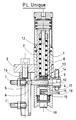
- the jack comprises a rod 1 sliding in a guide ring 2 secured to a frame 3.
- the tool mounted on the rod 1 is provided with a transverse pin 4 whose tip 5 slides in a groove 6 of the guide 16, so to prohibit the rotation of the rod 1.
- the rod 1 has an internal axis 8 whose head 9 is crossed by the pin 4.
- This pin 4 has a clearance 10 and a second flat 11, narrower, at 90 ° from the flat 10, serving for the precise and stable positioning of the pin 4.
- the axis 8 is surrounded by a helical spring 12 bearing on a ring 13 itself stopped by a stop 14.
- the other end of the rod 8 is integral from the other end of the spring 12.
- the head 9 of the axis 8 is opposite a recess 15 inside the rod 1, which allows a certain axial play of the rod 8, against the action of the spring 12. By partial decompression of the spring 12, it is thus possible to release the axis 4 and easily change the mechanism or the tool.
- This system which comprises a heavily loaded tie rod (of the order of 100 kg for example) and an axis with eccentric movement, can be used in general for the rapid fixing with stable positioning of any tool or workpiece in a machine, giving great flexibility of adaptation, to different types of parts for example.
- a sensor 17 of the inductive type is placed in a bore in the head of the pin 4 and cooperates with a parts feeler 19 and 18 in the tool. This detects the presence or absence of a part in the tool, as well as possibly the positioning of the part, without having a sensor in the tool itself. This avoids having to connect and adjust the sensor each time the tool is changed.
- the guide 8 also carries two sensors 7, 7 'cooperating with the tip 5 of the pin 4 to detect the limit switches of the jack.
- the sensors 7, 7 ′ can be replaced by limit switches.
Landscapes
- Engineering & Computer Science (AREA)
- Mechanical Engineering (AREA)
- Gripping On Spindles (AREA)
- Jigs For Machine Tools (AREA)
- Actuator (AREA)
Claims (9)
- Schnellspannvorrichtung von Werkzeugen oder Stückträgern der Art, daß sie eine Spannstange (1,8) und einen Stift (4) umfaßt, der das Werkzeug oder den Stückträger zu seiner Einspannung auf der Spannstange (1,8) durchkreuzt, wobei die Spannstange von einer in eine Stange (1) gleitende Achse (8) gebildet wird, und wobei der Stift (4) die genannte Stange (1) durchkreuzt, und er mit einer Freistich-Rechteckstange (10) ausgerüstet ist, dadurch gekennzeichnet, daß die Achse (8) mit einem Kopf (9) ausgestattet ist, der von dem Stift (4) durchkreuzt wird, und daß der Stift (4) drehbar um seine Achse angebracht ist, wobei die Achse (8) bezüglich der Stange (1) einer erhöhten Belastung (12) der Rückwärtsbewegung zum Stift (4) hin unterleigt, so daß sie unter erhöhtem Druck mit dem Stift (4) gehalten wird, um den Stift (4) in der Stange (1) einzuspannen.
- Vorrichtung nach Anspruch 1, dadurch gekennzeichnet, daß der Stift (4) eine zweite Rechteckstange (11) aufweist, die bezüglich der Freistich-Rechteckstange (10) winklig versetzt ist.
- Vorrichtung nach einem der Ansprüche 1 und 2, dadurch gekennzeichnet, daß der Stift (4) mit dem Kopf (9) der Achse (8) zusammenarbeitet, die von einer starken Belastungsfeder (12) in Druckstellung auf die Achse (4) zurückgestellt wird, wobei der Kopf (9) über ein axiales Spiel gegen die Bewegung der Feder (12) verfügt.
- Vorrichtung nach einem der Ansprüche 1 bis 3, dadurch gekennzeichnet, daß der Stift (4) mit einer Rille (6) zusammenarbeitet, um die Drehung des Apparates oder des Werkzeugs unmöglich zu machen.
- Vorrichtung nach einem der Ansprüche 1 bis 4, dadurch gekennzeichnet, daß das Ende (5) des Stiftes (4) mit zumindest einem Positionserfassungsorgan wie einem Lagesensor (7, 7') oder einem Lageschalter zusammenarbeitet.
- Vorrichtung nach einem der Ansprüche 1 bis 5, dadurch gekennzeichnet, daß der Kopf des Stiftes (4) von einer Bohrung durchstochen ist, die einen Sensor (17) der induktiven Art beherbergt, der mit einem Stückfühler (18,19) im Werkzeug zusammenarbeitet`
- Integrierte Führungswinde, die mit einer Vorrichtung gemäß einem der Ansprüche 1 bis 6 ausgerüstet ist, dadurch gekennzeichnet, daß ihre Stange von einer maßgeschliffenen Säule (1) gebildet wird, deren Durchmesser größer als Zweidrittel des Kolbendurchmessers ist, und die in einen festen Führungsring (2) gleitet, und daß die Winde Feststellmittel für die Drehung der Stange (1) oder des Werkzeugs, das auf der Stange (1) angebracht ist, besitzt.
- Winde nach Anspruch 7, dadurch gekennzeichnet, daß die genannten Mittel von einem querliegenden Stift (4) gebildet werden, der mit einer Rille (6) einer Führung (16) zusammenarbeitet.
- Winde nach Anspruch 8, dadurch gekennzeichnet, daß die Führung (16) Erfassungsmittel (7, 7') für die Nähe des Stiftes (4) zu zumindest einer Stelle der Führungsrille (6) aufweist, und daß die Mittel ein Erfassungssystem bilden für das Ende des Laufes der Stange (1).
Applications Claiming Priority (4)
| Application Number | Priority Date | Filing Date | Title |
|---|---|---|---|
| FR8715746 | 1987-11-06 | ||
| FR8715745 | 1987-11-06 | ||
| FR8715745A FR2622937B1 (fr) | 1987-11-06 | 1987-11-06 | Verin a guidage integre |
| FR8715746A FR2622822B1 (fr) | 1987-11-06 | 1987-11-06 | Dispositif de fixation rapide |
Publications (2)
| Publication Number | Publication Date |
|---|---|
| EP0315542A1 EP0315542A1 (de) | 1989-05-10 |
| EP0315542B1 true EP0315542B1 (de) | 1993-02-10 |
Family
ID=26226332
Family Applications (1)
| Application Number | Title | Priority Date | Filing Date |
|---|---|---|---|
| EP88402773A Expired - Lifetime EP0315542B1 (de) | 1987-11-06 | 1988-11-04 | Schnellspannvorrichtung und zugeordnete Kolben |
Country Status (3)
| Country | Link |
|---|---|
| US (1) | US4902178A (de) |
| EP (1) | EP0315542B1 (de) |
| DE (1) | DE3878401T2 (de) |
Families Citing this family (4)
| Publication number | Priority date | Publication date | Assignee | Title |
|---|---|---|---|---|
| DE102004038691A1 (de) * | 2003-09-27 | 2005-04-14 | Zf Friedrichshafen Ag | Wegmess-System für ein Kolben-Zylinderaggregat |
| CN106051279A (zh) * | 2016-07-27 | 2016-10-26 | 苏州好特斯模具有限公司 | 可定位阀针的方形活塞油缸系统 |
| CN111963536B (zh) * | 2020-07-31 | 2025-05-16 | 中国船舶重工集团应急预警与救援装备股份有限公司 | 一种立式板销接头 |
| CN112372021B (zh) * | 2020-11-19 | 2021-09-28 | 山东安瑞格精密机械有限公司 | 一种新能源汽车的刹车片加工用辅助装置 |
Family Cites Families (17)
| Publication number | Priority date | Publication date | Assignee | Title |
|---|---|---|---|---|
| GB790771A (en) * | 1954-10-18 | 1958-02-19 | E P Barrus Concessionaires Ltd | Improvements in and relating to hydraulic rams or jacks |
| DE1477376B2 (de) * | 1962-05-18 | 1970-11-26 | Haueisen & Sohn, 7540 Neuenbürg | Verlängerung für Werkzeugmaschinenspindeln |
| CH384980A (fr) * | 1962-08-25 | 1965-02-26 | Boillat S A | Dispositif de fixation et d'orientation d'une pièce sur une machine-outil |
| CH512954A (it) * | 1970-01-16 | 1971-09-30 | Olivetti & Co Spa | Dispositivo di bloccaggio dell'utensile sul mandrino di una macchina utensile |
| GB1390931A (en) * | 1971-02-02 | 1975-04-16 | Balding V H | Machine tools |
| US3717073A (en) * | 1971-06-23 | 1973-02-20 | Caterpillar Tractor Co | Proximity switch magnet control for bucket positioner |
| DE2256190A1 (de) * | 1972-11-16 | 1974-05-22 | Gildemeister Werkzeugmasch | Spanneinrichtung fuer mehrspindeldrehautomaten |
| DE2526902B2 (de) * | 1975-06-16 | 1981-08-27 | Stama Stark Maschinenfabrik Gotthilf Stark Gmbh & Co, 7311 Schlierbach | Werkzeugwechselvorrichtung |
| DE2544558C3 (de) * | 1975-10-03 | 1978-03-23 | Precise Gmbh Fabrik Fuer Elektrowerkzeuge, 5672 Leichingen | Einspanneinrichtung für eine Werkzeugeinheit in einer Spindel |
| CA1164287A (fr) * | 1981-02-16 | 1984-03-27 | Ernest Lacasse | Cylindre d'entrainement |
| AT381893B (de) * | 1981-11-06 | 1986-12-10 | Orlik Josef | Aufspannvorrichtung |
| DE3237057A1 (de) * | 1982-10-06 | 1984-04-12 | Hilti AG, 9494 Schaan | Stativbohrgeraet |
| DE3541638A1 (de) * | 1985-11-26 | 1986-04-30 | Josip 6954 Haßmersheim Siniko | Werkstueckhaltevorrichtung |
| DE8533253U1 (de) * | 1985-11-26 | 1986-01-16 | Karl Hertel GmbH, 8510 Fürth | Schnellwechsel-Einspannvorrichtung |
| DE3602247C2 (de) * | 1986-01-25 | 1997-01-23 | Widia Gmbh | Werkzeugkupplung zur Verbindung eines wechselbaren Werkzeugkopfes mit einem Werkzeughalter an einer Werkzeugmaschine |
| SU1397195A1 (ru) * | 1986-05-13 | 1988-06-15 | А. П. Коржов | Устройство дл креплени хвостовиков |
| DE8631442U1 (de) * | 1986-11-25 | 1988-03-24 | Komet Stahlhalter- Und Werkzeugfabrik Robert Breuning Gmbh, 7122 Besigheim | Werkzeugmaschinenspindel und hierzu passende Werkzeughalter |
-
1988
- 1988-10-31 US US07/264,362 patent/US4902178A/en not_active Expired - Lifetime
- 1988-11-04 EP EP88402773A patent/EP0315542B1/de not_active Expired - Lifetime
- 1988-11-04 DE DE8888402773T patent/DE3878401T2/de not_active Expired - Fee Related
Also Published As
| Publication number | Publication date |
|---|---|
| DE3878401T2 (de) | 1993-09-23 |
| DE3878401D1 (de) | 1993-03-25 |
| EP0315542A1 (de) | 1989-05-10 |
| US4902178A (en) | 1990-02-20 |
Similar Documents
| Publication | Publication Date | Title |
|---|---|---|
| EP0571620A1 (de) | Vorrichtung zur schnellen montierung und demontierung einer achse, z.b. ein fahrradpedal. | |
| EP0315542A1 (de) | Schnellspannvorrichtung und zugeordnete Kolben | |
| EP3328587B1 (de) | Vorrichtung zum spannen eines werkstücks auf einem werkzeug | |
| BE898143A (fr) | Dispositif de relèvement de la position d'un évidement dans une pièce relativement grande, notamment en tole. | |
| CH635657A5 (fr) | Mecanisme d'accouplement. | |
| FR2622822A1 (fr) | Dispositif de fixation rapide | |
| FR2618713A1 (fr) | Dispositif de bridage | |
| EP1697088B1 (de) | Schnellklemmvorrichtung und steuerverfahren | |
| FR2468874A1 (fr) | Instrument servant a calibrer des pieces presentant un axe de symetrie | |
| FR2789340A1 (fr) | Machine de marquage | |
| EP0085613B1 (de) | Spannvorrichtung für ein Werkstück | |
| FR2490130A1 (fr) | Dispositif pour emmancher une piece femelle sur une piece male | |
| FR2546242A1 (fr) | Detecteur mecanique de position de fin de course | |
| FR2622937A1 (fr) | Verin a guidage integre | |
| EP0286592A1 (de) | Handhabungsgreifer, insbesondere für automatische Montagegeräte | |
| FR2705079A1 (fr) | Dispositif de commande pour frein et dérailleur de cycle. | |
| FR2566494A1 (fr) | Appareil a cylindre de frein et mecanisme de regleur de jeu notamment pour vehicules ferroviaires | |
| CH691879A5 (fr) | Appareil de mesure de longueurs. | |
| CH669133A5 (fr) | Mandrin comportant des moyens de commande de la position d'un outil. | |
| BE533877A (de) | ||
| FR2605916A1 (fr) | Etau a serrage rapide manuel | |
| CH341698A (fr) | Porte-outil à aléser | |
| CH318540A (fr) | Dispositif d'actionnement d'un organe de serrage d'une pièce en ouvrage sur une machine-outil | |
| FR2871717A3 (fr) | Serre-joint avec mecanisme de serrage a piston, une tige filetee a un filet et des spheres d'acier | |
| FR2622836A1 (de) |
Legal Events
| Date | Code | Title | Description |
|---|---|---|---|
| PUAI | Public reference made under article 153(3) epc to a published international application that has entered the european phase |
Free format text: ORIGINAL CODE: 0009012 |
|
| AK | Designated contracting states |
Kind code of ref document: A1 Designated state(s): CH DE ES FR GB IT LI |
|
| 17P | Request for examination filed |
Effective date: 19890529 |
|
| 17Q | First examination report despatched |
Effective date: 19900928 |
|
| GRAA | (expected) grant |
Free format text: ORIGINAL CODE: 0009210 |
|
| AK | Designated contracting states |
Kind code of ref document: B1 Designated state(s): CH DE ES FR GB IT LI |
|
| PG25 | Lapsed in a contracting state [announced via postgrant information from national office to epo] |
Ref country code: ES Free format text: THE PATENT HAS BEEN ANNULLED BY A DECISION OF A NATIONAL AUTHORITY Effective date: 19930210 |
|
| REF | Corresponds to: |
Ref document number: 3878401 Country of ref document: DE Date of ref document: 19930325 |
|
| ITF | It: translation for a ep patent filed | ||
| GBT | Gb: translation of ep patent filed (gb section 77(6)(a)/1977) |
Effective date: 19930526 |
|
| PG25 | Lapsed in a contracting state [announced via postgrant information from national office to epo] |
Ref country code: LI Effective date: 19931130 Ref country code: CH Effective date: 19931130 |
|
| PLBE | No opposition filed within time limit |
Free format text: ORIGINAL CODE: 0009261 |
|
| STAA | Information on the status of an ep patent application or granted ep patent |
Free format text: STATUS: NO OPPOSITION FILED WITHIN TIME LIMIT |
|
| 26N | No opposition filed | ||
| REG | Reference to a national code |
Ref country code: CH Ref legal event code: PL |
|
| REG | Reference to a national code |
Ref country code: GB Ref legal event code: IF02 |
|
| PG25 | Lapsed in a contracting state [announced via postgrant information from national office to epo] |
Ref country code: FR Free format text: LAPSE BECAUSE OF NON-PAYMENT OF DUE FEES Effective date: 20060731 |
|
| PGFP | Annual fee paid to national office [announced via postgrant information from national office to epo] |
Ref country code: GB Payment date: 20061101 Year of fee payment: 19 |
|
| PGFP | Annual fee paid to national office [announced via postgrant information from national office to epo] |
Ref country code: DE Payment date: 20061102 Year of fee payment: 19 |
|
| REG | Reference to a national code |
Ref country code: FR Ref legal event code: ST Effective date: 20060731 |
|
| PGFP | Annual fee paid to national office [announced via postgrant information from national office to epo] |
Ref country code: IT Payment date: 20061130 Year of fee payment: 19 |
|
| REG | Reference to a national code |
Ref country code: FR Ref legal event code: RN |
|
| REG | Reference to a national code |
Ref country code: FR Ref legal event code: FC |
|
| PGRI | Patent reinstated in contracting state [announced from national office to epo] |
Ref country code: FR Effective date: 20061129 |
|
| PGFP | Annual fee paid to national office [announced via postgrant information from national office to epo] |
Ref country code: FR Payment date: 20071107 Year of fee payment: 20 |
|
| GBPC | Gb: european patent ceased through non-payment of renewal fee |
Effective date: 20071104 |
|
| PG25 | Lapsed in a contracting state [announced via postgrant information from national office to epo] |
Ref country code: DE Free format text: LAPSE BECAUSE OF NON-PAYMENT OF DUE FEES Effective date: 20080603 |
|
| PG25 | Lapsed in a contracting state [announced via postgrant information from national office to epo] |
Ref country code: GB Free format text: LAPSE BECAUSE OF NON-PAYMENT OF DUE FEES Effective date: 20071104 |
|
| PG25 | Lapsed in a contracting state [announced via postgrant information from national office to epo] |
Ref country code: IT Free format text: LAPSE BECAUSE OF NON-PAYMENT OF DUE FEES Effective date: 20071104 |