EP0315544A1 - Fourchette de fixation d'un barillet de serrure - Google Patents
Fourchette de fixation d'un barillet de serrure Download PDFInfo
- Publication number
- EP0315544A1 EP0315544A1 EP88402775A EP88402775A EP0315544A1 EP 0315544 A1 EP0315544 A1 EP 0315544A1 EP 88402775 A EP88402775 A EP 88402775A EP 88402775 A EP88402775 A EP 88402775A EP 0315544 A1 EP0315544 A1 EP 0315544A1
- Authority
- EP
- European Patent Office
- Prior art keywords
- fork
- barrel
- wings
- fork according
- head
- Prior art date
- Legal status (The legal status is an assumption and is not a legal conclusion. Google has not performed a legal analysis and makes no representation as to the accuracy of the status listed.)
- Granted
Links
- 229910052751 metal Inorganic materials 0.000 claims description 4
- 239000002184 metal Substances 0.000 claims description 4
- 229920002994 synthetic fiber Polymers 0.000 claims description 2
- HCHKCACWOHOZIP-UHFFFAOYSA-N Zinc Chemical compound [Zn] HCHKCACWOHOZIP-UHFFFAOYSA-N 0.000 description 1
- 229910052782 aluminium Inorganic materials 0.000 description 1
- XAGFODPZIPBFFR-UHFFFAOYSA-N aluminium Chemical compound [Al] XAGFODPZIPBFFR-UHFFFAOYSA-N 0.000 description 1
- 239000000463 material Substances 0.000 description 1
- 229910001092 metal group alloy Inorganic materials 0.000 description 1
- 230000010355 oscillation Effects 0.000 description 1
- 230000002093 peripheral effect Effects 0.000 description 1
- 230000000284 resting effect Effects 0.000 description 1
- 229910052725 zinc Inorganic materials 0.000 description 1
- 239000011701 zinc Substances 0.000 description 1
Images
Classifications
-
- E—FIXED CONSTRUCTIONS
- E05—LOCKS; KEYS; WINDOW OR DOOR FITTINGS; SAFES
- E05B—LOCKS; ACCESSORIES THEREFOR; HANDCUFFS
- E05B9/00—Lock casings or latch-mechanism casings ; Fastening locks or fasteners or parts thereof to the wing
- E05B9/08—Fastening locks or fasteners or parts thereof, e.g. the casings of latch-bolt locks or cylinder locks to the wing
- E05B9/084—Fastening of lock cylinders, plugs or cores
-
- Y—GENERAL TAGGING OF NEW TECHNOLOGICAL DEVELOPMENTS; GENERAL TAGGING OF CROSS-SECTIONAL TECHNOLOGIES SPANNING OVER SEVERAL SECTIONS OF THE IPC; TECHNICAL SUBJECTS COVERED BY FORMER USPC CROSS-REFERENCE ART COLLECTIONS [XRACs] AND DIGESTS
- Y10—TECHNICAL SUBJECTS COVERED BY FORMER USPC
- Y10T—TECHNICAL SUBJECTS COVERED BY FORMER US CLASSIFICATION
- Y10T70/00—Locks
- Y10T70/70—Operating mechanism
- Y10T70/7441—Key
- Y10T70/7486—Single key
- Y10T70/7508—Tumbler type
- Y10T70/7559—Cylinder type
- Y10T70/7655—Cylinder attaching or mounting means
-
- Y—GENERAL TAGGING OF NEW TECHNOLOGICAL DEVELOPMENTS; GENERAL TAGGING OF CROSS-SECTIONAL TECHNOLOGIES SPANNING OVER SEVERAL SECTIONS OF THE IPC; TECHNICAL SUBJECTS COVERED BY FORMER USPC CROSS-REFERENCE ART COLLECTIONS [XRACs] AND DIGESTS
- Y10—TECHNICAL SUBJECTS COVERED BY FORMER USPC
- Y10T—TECHNICAL SUBJECTS COVERED BY FORMER US CLASSIFICATION
- Y10T70/00—Locks
- Y10T70/80—Parts, attachments, accessories and adjuncts
- Y10T70/8432—For key-operated mechanism
- Y10T70/8459—Housings
- Y10T70/8541—Mounting arrangements
Definitions
- the invention relates to a fixing fork for a lock cylinder, in particular but not exclusively for the doors of motor vehicles.
- the fork placed under the head of the barrel, keeps it pressed against a fixing panel, with the interposition of an elastic seal.
- a tool placed in the key channel of the barrel allows it to oscillate so that, by successive alternating movements, it is possible to make the fork crawl and extract the barrel, which gives access to the lock.
- the present invention aims to provide a new fixing fork prohibiting giving the barrel such successive oscillating movements.
- the fork according to the invention is characterized in that it is in one piece with a second fork cooperating with the end of the barrel opposite the head, the assembly being provided with wings of support on the fixing panel.
- the part can be made of folded cut sheet metal or of molded material.
- the constitution of the fork in a part provided with lateral wings and a second fork in abutment on one end of the barrel forms an extremely rigid assembly, any attempt to set the barrel in oscillation producing a bracing of the part and the barrel.
- the lateral wings are formed in the extension of the first fork. In a variant, the lateral wings are formed at the ends of the arms protruding from the second fork.
- the two forks are connected by a wall connecting their heads.
- the two forks are connected by side walls.
- the fork 1 is extended laterally by two wings 2 while its head, opposite the slot 3, is extended by a wall 4 orthogonal, itself adjacent to a second fork 5 parallel to fork 1 and in the same direction.
- the fork 1 is housed in a peripheral slot 6 of the barrel 7, against the fixing panel 8 on which the head 9 of the barrel 7 is supported.
- An elastic seal 10 is also housed in the slot 6
- the wings 2 of the fork 1 are corrugated longitudinally so that the fork 1 has support pads and exerts on the barrel 7 a force directed inwards, so that the head 9 of the barrel 7 is compressed against the external face of the panel 8.
- the second fork 5 surrounds the end 11 of the barrel 7.
- the assembly formed by the two forks 1 and 5 resting on the barrel 7 and connected between them by the wall 4 is very rigid and braced on the panel 8, so that it is practically impossible to cause the barrel 7 to oscillate.
- the support wings 2 are flat and are each connected to the second fork 5 by an inclined wall 12. It is the articulation of the walls 12 on the fork 5 which provides the elastic force of support of the wings 2 against the inner face of the panel 8.
- the fork 5 is connected directly to the end of each of the wings 2 by inclined walls 13, the wings 2 being corrugated transversely.
- the assembly has a longitudinal trapezoidal section.
- FIGS. 1 to 5 relate to pieces of cut and bent metal, which can be welded in the case of FIG. 5.
- FIG. 6 relates to a closed part molded from synthetic material or from a metal alloy, for example based on zinc or aluminum. In this case, provision can be made to provide the wings 2 with support pads 14.
Landscapes
- Engineering & Computer Science (AREA)
- Mechanical Engineering (AREA)
- Lock And Its Accessories (AREA)
- Superstructure Of Vehicle (AREA)
- Piezo-Electric Or Mechanical Vibrators, Or Delay Or Filter Circuits (AREA)
- Insertion Pins And Rivets (AREA)
Abstract
Description
- L'invention concerne une fourchette de fixation d'un barillet de serrure, en particulier mais non exclusivement pour les portes de véhicules automobiles.
- Habituellement, la fourchette, placée sous la tête du barillet, maintient celle-ci plaquée contre un panneau de fixation, avec interposition d'un joint élastique.
- Un outil placé dans la canal de clé du barillet permet de le faire osciller de sorte que,par mouvements alternés successifs, il est possible de faire ramper la fourchette et d'extraire le barillet, ce qui donne accès à la serrure.
- Le présente invention vise à fournir une nouvelle fourchette de fixation interdisant de donner au barillet de tels mouvements successifs d'oscillation.
- A cet effet, la fourchette selon l'invention est caractérisée par le fait qu'elle est d'une seule pièce avec une seconde fourchette coopérant avec l'extrémité du barillet opposée à la tête, l'ensemble étant muni d'ailes d'appui sur le panneau de fixation.
- La pièce peut être en tôle découpée pliée ou en matière moulée.
- La constitution de la fourchette en une pièce munie d'ailes latérales et d'une seconde fourchette en appui sur une extrémité du barillet forme un ensemble extrêmement rigide, toute tentative de mise en oscillation du barillet produisant un arc-boutement de la pièce et du barillet.
- Dans une forme de réalisation, les ailes latérales sont formées dans le prolongement de la première fourchette. Dans une variante, les ailes latérales sont formées aux extrémités de bras dépassant de la seconde fourchette.
- Selon une forme de réalisation de l'invention, les deux fourchettes sont reliées par une paroi raccordant leurs têtes.
- Selon une variante, les deux fourchettes sont reliées par des parois latérales.
- L'invention sera bien comprise à la lecture de la description suivante faite en se référant au dessin annexé dans lequel:
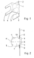
- - la figure 1 est une vue schématique en perspective d'une fourchette selon un exemple de réalisation de l'invention,
- - la figure 2 est une vue schématique en élévation latérale de la fourchette de la figure 1 après montage sur un panneau,
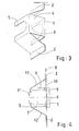
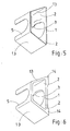
- - les figures 3,5 et 6 sont des vues schématiques en perspective de variantes de la fourchette selon l'invention, et
- - la figure 4 est analogue à la figure 2, pour la fourchette de la figure 3.
- Dans l'exemple de réalisation des figures 1 et 2, la fourchette 1 est prolongée latéralement par deux ailes 2 alors que sa tête , opposée à la fente 3, est prolongée par une paroi 4 orthogonale, elle-même adjacente à une seconde fourchette 5 parallèle à la fourchette 1 et de même sens.
- Au montage ( figure 2 ), la fourchette 1 est logée dans une fente périphérique 6 du barillet 7, contre le panneau de fixation 8 sur lequel est en appui la tête 9 du barillet 7. Un joint élastique 10 est également logé dans la fente 6. Les ailes 2 de la fourchette 1 sont ondulées longitudinalement de manière que la fourchette 1 comporte des patins d'appui et exerce sur le barillet 7 une force dirigée vers l'intérieur, de sorte que la tête 9 du barillet 7 est comprimée contre la face externe du panneau 8.
- La seconde fourchette 5 entoure l'extrémité 11 du barillet 7. L'ensemble formé par les deux fourchettes 1 et 5 en appui sur le barillet 7 et reliées entre elles par la paroi 4 est très rigide et arc-bouté sur le panneau 8, de sorte qu'il est pratiquement impossible de faire osciller le barillet 7.
- Dans la forme de réalisation des figures 3 et 4,où les mêmes références désignent les mêmes éléments qu'aux figures 1 et 2, les ailes d'appui 2 sont planes et sont reliées chacune à la seconde fourchette 5 par une paroi inclinée 12. C'est l'articulation des parois 12 sur la fourchette 5 qui fournit la force élastique d'appui des ailes 2 contre la face intérieure du panneau 8.
- Dans les variantes des figures 5 et 6, la fourchette 5 est reliée directement à l'extrémité de chacune des ailes 2 par des parois inclinées 13, les ailes 2 étant ondulées transversalement. L'ensemble a une section longitudinale trapézoïdale.
- Les formes de réalisation des figures 1 à 5 concernent des pièces en métal découpé et plié, qui peut être soudé dans le cas de la figure 5.
- La forme de réalisation de la figure 6 concerne une pièce fermée moulée en matière synthétique ou en alliage métallique, par exemple à base de zinc ou d'aluminium. On peut prévoir dans ce cas de munir les ailes 2 de patins d'appui 14.
Claims (10)
Applications Claiming Priority (2)
| Application Number | Priority Date | Filing Date | Title |
|---|---|---|---|
| FR8715752A FR2622916B1 (fr) | 1987-11-06 | 1987-11-06 | Fourchette de fixation d'un barillet de serrure |
| FR8715752 | 1987-11-06 |
Publications (2)
| Publication Number | Publication Date |
|---|---|
| EP0315544A1 true EP0315544A1 (fr) | 1989-05-10 |
| EP0315544B1 EP0315544B1 (fr) | 1992-07-29 |
Family
ID=9356789
Family Applications (1)
| Application Number | Title | Priority Date | Filing Date |
|---|---|---|---|
| EP88402775A Expired - Lifetime EP0315544B1 (fr) | 1987-11-06 | 1988-11-04 | Fourchette de fixation d'un barillet de serrure |
Country Status (4)
| Country | Link |
|---|---|
| US (1) | US4873852A (fr) |
| EP (1) | EP0315544B1 (fr) |
| DE (1) | DE3873264T2 (fr) |
| FR (1) | FR2622916B1 (fr) |
Cited By (1)
| Publication number | Priority date | Publication date | Assignee | Title |
|---|---|---|---|---|
| CN114016827A (zh) * | 2017-11-10 | 2022-02-08 | 索斯科公司 | 杠杆式压缩闩锁 |
Families Citing this family (15)
| Publication number | Priority date | Publication date | Assignee | Title |
|---|---|---|---|---|
| DE8911765U1 (de) * | 1989-10-03 | 1991-01-31 | Ramsauer, Dieter, 5620 Velbert | Verschlußgehäuse mit Flansch zur Montage in einem Durchbruch einer dünnwandigen Fläche, insbesondere Blechschranktür oder Blechkastendeckel |
| US5410899A (en) * | 1993-04-22 | 1995-05-02 | Tri/Mark Corporation | Retainer clip for escutcheon assembly |
| US5487287A (en) * | 1993-09-02 | 1996-01-30 | Viggiano; Mark S. | Quick-release lock retaining bracket method and apparatus |
| US5678437A (en) * | 1995-03-17 | 1997-10-21 | Walla; Gregg | Lock for furniture closure |
| US5551268A (en) * | 1995-04-03 | 1996-09-03 | Chrysler Corporation | Retainer assembly for a lock cylinder |
| US6079241A (en) * | 1998-04-27 | 2000-06-27 | Slc Technologies, Inc. | Method and apparatus for lock mounting |
| JP4073553B2 (ja) * | 1998-09-02 | 2008-04-09 | 本田技研工業株式会社 | キーシリンダの取付構造 |
| US6014876A (en) * | 1999-01-04 | 2000-01-18 | Ford Global Technologies, Inc. | Adjustable locking for hood latch |
| US6161404A (en) * | 1999-06-16 | 2000-12-19 | Westwinkel; Florian | Mounting clip for a removable locking core |
| US6568229B1 (en) | 2001-02-27 | 2003-05-27 | The Eastern Company | Key operated switch having removable clip retained switch assembly |
| FR2833291B1 (fr) | 2001-12-11 | 2007-02-23 | Ronis Sa | Serrure auto-clipsable dans un ajour d'un support |
| USD482596S1 (en) | 2002-05-22 | 2003-11-25 | The Eastern Company | Portions of a cam lock with retaining clip |
| US7444845B2 (en) * | 2006-10-16 | 2008-11-04 | Chrysler Llc | Retainer for a door lock |
| US8104850B2 (en) | 2007-05-30 | 2012-01-31 | Steelcase Inc. | Furniture storage unit |
| US9399879B2 (en) * | 2011-04-29 | 2016-07-26 | Trimark Corporation | Vehicle compartment door handle assembly |
Citations (2)
| Publication number | Priority date | Publication date | Assignee | Title |
|---|---|---|---|---|
| US2549724A (en) * | 1948-05-25 | 1951-04-17 | Tinnerman Products Inc | Fastening device |
| US2948141A (en) * | 1957-05-31 | 1960-08-09 | American Hardware Corp | Means for retaining a lock cylinder in a panel |
Family Cites Families (4)
| Publication number | Priority date | Publication date | Assignee | Title |
|---|---|---|---|---|
| US2443362A (en) * | 1947-03-31 | 1948-06-15 | Tinnerman Products Inc | Fastening device |
| US2629248A (en) * | 1949-01-19 | 1953-02-24 | Illinois Tool Works | Door lock retainer |
| US3488984A (en) * | 1967-05-05 | 1970-01-13 | Emhart Corp | Closure latch and closure |
| FR2360727A1 (fr) * | 1976-08-02 | 1978-03-03 | Neiman Sa | Serrure munie d'un dispositif de protection contre l'eau |
-
1987
- 1987-11-06 FR FR8715752A patent/FR2622916B1/fr not_active Expired - Lifetime
-
1988
- 1988-10-31 US US07/264,361 patent/US4873852A/en not_active Expired - Fee Related
- 1988-11-04 EP EP88402775A patent/EP0315544B1/fr not_active Expired - Lifetime
- 1988-11-04 DE DE8888402775T patent/DE3873264T2/de not_active Expired - Fee Related
Patent Citations (2)
| Publication number | Priority date | Publication date | Assignee | Title |
|---|---|---|---|---|
| US2549724A (en) * | 1948-05-25 | 1951-04-17 | Tinnerman Products Inc | Fastening device |
| US2948141A (en) * | 1957-05-31 | 1960-08-09 | American Hardware Corp | Means for retaining a lock cylinder in a panel |
Cited By (3)
| Publication number | Priority date | Publication date | Assignee | Title |
|---|---|---|---|---|
| CN114016827A (zh) * | 2017-11-10 | 2022-02-08 | 索斯科公司 | 杠杆式压缩闩锁 |
| CN114016827B (zh) * | 2017-11-10 | 2023-12-22 | 索斯科公司 | 杠杆式压缩闩锁 |
| US12291891B2 (en) | 2017-11-10 | 2025-05-06 | Southco, Inc. | Lever compression latch |
Also Published As
| Publication number | Publication date |
|---|---|
| DE3873264T2 (de) | 1993-01-14 |
| DE3873264D1 (de) | 1992-09-03 |
| US4873852A (en) | 1989-10-17 |
| FR2622916A1 (fr) | 1989-05-12 |
| FR2622916B1 (fr) | 1990-02-23 |
| EP0315544B1 (fr) | 1992-07-29 |
Similar Documents
| Publication | Publication Date | Title |
|---|---|---|
| EP0315544A1 (fr) | Fourchette de fixation d'un barillet de serrure | |
| US4762904A (en) | Plastic window glass holder | |
| FR2528741A1 (fr) | Appareil de serrage d'une plaque de fermeture sur une fermeture a coulisse d'un orifice de coulee sur un reservoir contenant un bain de fusion | |
| EP2795141B1 (fr) | Systeme permettant la fixation d'un objet sur un element a rainure(s) de fixation et dispositif de fixation pour un tel systeme | |
| EP1818485A1 (fr) | Dispositif de verrouillage à au moins un point de condamnation | |
| US5779421A (en) | Insulation fastening device | |
| FR2741677A1 (fr) | Dispositif de fixation servant a fixer un element de tole a une surface, dans une position distante de cette surface | |
| EP0209444B1 (fr) | Ensemble de serrure de porte, notamment pour véhicule automobile | |
| EP1013827A1 (fr) | Dispositif de fixation de rails | |
| EP2017408B1 (fr) | Dispositif de prépositionnement d'une gâche destinée à coopérer avec une serrure d'un ouvrant de véhicule automobile et véhicule automobile comportant au moins un tel dispositif | |
| BE887089A (fr) | Encadrement metallique pour porte | |
| FR2798971A1 (fr) | Agencement de fixation d'un element encastrable dans une ouverture d'emplacement d'une plaque de support | |
| FR2796427A1 (fr) | Dispositif de premontage d'un ecrou pour ensemble de fixation du type vis-ecrou | |
| EP2956607A2 (fr) | Serrure de vehicule automobile | |
| BE1003433A6 (fr) | Dispositif de fixation. | |
| FR2666525A1 (fr) | Dispositif de montage d'une pince pour la tenue du bas de caisse d'un vehicule sur un marbre destine a la reparation de la carrosserie de ce vehicule. | |
| FR2475107A1 (fr) | Dispositif de fixation d'un chassis de porte, notamment pour une porte de garage | |
| CA1298592C (fr) | Cremone automatique a double action | |
| FR2809473A1 (fr) | Support pour la fixation d'une tablette a une paroi | |
| FR3114360A1 (fr) | Un élément de fixation et une pièce comprenant cet élément | |
| FR2461799A1 (fr) | Coffre-fort ou analogue avec panneau de porte encastre | |
| FR2639300A1 (fr) | Balai d'essuie-glace a cale incorporee | |
| FR2701994A1 (fr) | Support de fixation assemblé pour charnon d'articulation. | |
| FR2472071A1 (fr) | Dispositif de suspension pour portes ou portails | |
| FR2802455A1 (fr) | Dispositif d'extracteur d'electrode |
Legal Events
| Date | Code | Title | Description |
|---|---|---|---|
| PUAI | Public reference made under article 153(3) epc to a published international application that has entered the european phase |
Free format text: ORIGINAL CODE: 0009012 |
|
| AK | Designated contracting states |
Kind code of ref document: A1 Designated state(s): DE ES FR GB IT |
|
| 17P | Request for examination filed |
Effective date: 19890529 |
|
| 17Q | First examination report despatched |
Effective date: 19900904 |
|
| GRAA | (expected) grant |
Free format text: ORIGINAL CODE: 0009210 |
|
| AK | Designated contracting states |
Kind code of ref document: B1 Designated state(s): DE ES FR GB IT |
|
| PG25 | Lapsed in a contracting state [announced via postgrant information from national office to epo] |
Ref country code: ES Free format text: THE PATENT HAS BEEN ANNULLED BY A DECISION OF A NATIONAL AUTHORITY Effective date: 19920729 Ref country code: IT Free format text: LAPSE BECAUSE OF FAILURE TO SUBMIT A TRANSLATION OF THE DESCRIPTION OR TO PAY THE FEE WITHIN THE PRE;WARNING: LAPSES OF ITALIAN PATENTS WITH EFFECTIVE DATE BEFORE 2007 MAY HAVE OCCURRED AT ANY TIME BEFORE 2007. THE CORRECT EFFECTIVE DATE MAY BE DIFFERENT FROM THE ONE RECORDED.SCRIBED TIME-LIMIT Effective date: 19920729 |
|
| REF | Corresponds to: |
Ref document number: 3873264 Country of ref document: DE Date of ref document: 19920903 |
|
| GBT | Gb: translation of ep patent filed (gb section 77(6)(a)/1977) | ||
| PLBE | No opposition filed within time limit |
Free format text: ORIGINAL CODE: 0009261 |
|
| STAA | Information on the status of an ep patent application or granted ep patent |
Free format text: STATUS: NO OPPOSITION FILED WITHIN TIME LIMIT |
|
| 26N | No opposition filed | ||
| REG | Reference to a national code |
Ref country code: GB Ref legal event code: IF02 |
|
| PGFP | Annual fee paid to national office [announced via postgrant information from national office to epo] |
Ref country code: FR Payment date: 20031112 Year of fee payment: 16 |
|
| PGFP | Annual fee paid to national office [announced via postgrant information from national office to epo] |
Ref country code: GB Payment date: 20041104 Year of fee payment: 17 Ref country code: DE Payment date: 20041104 Year of fee payment: 17 |
|
| PG25 | Lapsed in a contracting state [announced via postgrant information from national office to epo] |
Ref country code: FR Free format text: LAPSE BECAUSE OF NON-PAYMENT OF DUE FEES Effective date: 20050729 |
|
| REG | Reference to a national code |
Ref country code: FR Ref legal event code: ST |
|
| PG25 | Lapsed in a contracting state [announced via postgrant information from national office to epo] |
Ref country code: GB Free format text: LAPSE BECAUSE OF NON-PAYMENT OF DUE FEES Effective date: 20051104 |
|
| PG25 | Lapsed in a contracting state [announced via postgrant information from national office to epo] |
Ref country code: DE Free format text: LAPSE BECAUSE OF NON-PAYMENT OF DUE FEES Effective date: 20060601 |
|
| GBPC | Gb: european patent ceased through non-payment of renewal fee |
Effective date: 20051104 |