EP0315548B1 - Profilierte Spundbohlen mit komplementären, seitlich offenen Schlosshaken, und aus diesen Spundbohlen zusammengesetzte Spundwände - Google Patents
Profilierte Spundbohlen mit komplementären, seitlich offenen Schlosshaken, und aus diesen Spundbohlen zusammengesetzte Spundwände Download PDFInfo
- Publication number
- EP0315548B1 EP0315548B1 EP88402785A EP88402785A EP0315548B1 EP 0315548 B1 EP0315548 B1 EP 0315548B1 EP 88402785 A EP88402785 A EP 88402785A EP 88402785 A EP88402785 A EP 88402785A EP 0315548 B1 EP0315548 B1 EP 0315548B1
- Authority
- EP
- European Patent Office
- Prior art keywords
- flange
- male
- female
- piling
- web
- Prior art date
- Legal status (The legal status is an assumption and is not a legal conclusion. Google has not performed a legal analysis and makes no representation as to the accuracy of the status listed.)
- Expired - Lifetime
Links
- 230000000295 complement effect Effects 0.000 title claims abstract description 22
- 239000002184 metal Substances 0.000 title claims abstract description 20
- 230000008878 coupling Effects 0.000 title claims abstract 12
- 238000010168 coupling process Methods 0.000 title claims abstract 12
- 238000005859 coupling reaction Methods 0.000 title claims abstract 12
- 230000007935 neutral effect Effects 0.000 claims description 9
- 238000000034 method Methods 0.000 claims description 7
- 230000001154 acute effect Effects 0.000 claims description 4
- 238000007493 shaping process Methods 0.000 claims 2
- 238000004519 manufacturing process Methods 0.000 abstract description 4
- 238000005452 bending Methods 0.000 abstract description 3
- 238000010276 construction Methods 0.000 description 7
- 229920000297 Rayon Polymers 0.000 description 3
- 239000000463 material Substances 0.000 description 3
- 239000002964 rayon Substances 0.000 description 3
- 230000003014 reinforcing effect Effects 0.000 description 3
- 239000000565 sealant Substances 0.000 description 3
- 229910000831 Steel Inorganic materials 0.000 description 2
- 230000015572 biosynthetic process Effects 0.000 description 2
- 239000004568 cement Substances 0.000 description 2
- 238000002347 injection Methods 0.000 description 2
- 239000007924 injection Substances 0.000 description 2
- 239000007788 liquid Substances 0.000 description 2
- 230000004224 protection Effects 0.000 description 2
- 239000011347 resin Substances 0.000 description 2
- 229920005989 resin Polymers 0.000 description 2
- 230000000284 resting effect Effects 0.000 description 2
- 238000007789 sealing Methods 0.000 description 2
- 239000007787 solid Substances 0.000 description 2
- 239000010959 steel Substances 0.000 description 2
- 238000009412 basement excavation Methods 0.000 description 1
- 239000004567 concrete Substances 0.000 description 1
- 230000007123 defense Effects 0.000 description 1
- 239000007789 gas Substances 0.000 description 1
- 229930195733 hydrocarbon Natural products 0.000 description 1
- 150000002430 hydrocarbons Chemical class 0.000 description 1
- 238000003825 pressing Methods 0.000 description 1
- 230000001681 protective effect Effects 0.000 description 1
- 230000002787 reinforcement Effects 0.000 description 1
- 239000011435 rock Substances 0.000 description 1
- 238000003860 storage Methods 0.000 description 1
- 230000009182 swimming Effects 0.000 description 1
- 239000002699 waste material Substances 0.000 description 1
- 239000002023 wood Substances 0.000 description 1
Images





Classifications
-
- E—FIXED CONSTRUCTIONS
- E02—HYDRAULIC ENGINEERING; FOUNDATIONS; SOIL SHIFTING
- E02D—FOUNDATIONS; EXCAVATIONS; EMBANKMENTS; UNDERGROUND OR UNDERWATER STRUCTURES
- E02D5/00—Bulkheads, piles, or other structural elements specially adapted to foundation engineering
- E02D5/02—Sheet piles or sheet pile bulkheads
- E02D5/03—Prefabricated parts, e.g. composite sheet piles
- E02D5/04—Prefabricated parts, e.g. composite sheet piles made of steel
-
- E—FIXED CONSTRUCTIONS
- E02—HYDRAULIC ENGINEERING; FOUNDATIONS; SOIL SHIFTING
- E02D—FOUNDATIONS; EXCAVATIONS; EMBANKMENTS; UNDERGROUND OR UNDERWATER STRUCTURES
- E02D5/00—Bulkheads, piles, or other structural elements specially adapted to foundation engineering
- E02D5/02—Sheet piles or sheet pile bulkheads
- E02D5/03—Prefabricated parts, e.g. composite sheet piles
- E02D5/04—Prefabricated parts, e.g. composite sheet piles made of steel
- E02D5/08—Locking forms; Edge joints; Pile crossings; Branch pieces
Definitions
- the present invention relates to profiled metal sheet piles, used in the building industry and public works, for the realization of foundation, retaining or protective works, works whose role is to separate two environments, generally a liquid environment of a solid medium and sometimes a gaseous medium of a liquid medium or of a solid medium.
- sheet piles for construction: curtains for the defense of the banks of canals and rivers; flood protection screens along roads and highways in flood-prone areas; quay walls in ports and along rivers; perimeter walls of swimming pools; silos; containment walls of basins for the storage of gases, in particular of hydrocarbons; trench armor, during excavations; terrestrial retaining curtains; protections along the roads to prevent falling rocks.
- a suitable product such as a cement or a resin, is injected into the empty space which may remain between the two complementary means engaged by each latch formed by the juxtaposition of two neighboring sheet piles.
- the present invention relates more precisely to the field of profiled metal sheet piles with complementary open side loops.
- loop sheet piles form longitudinal locks with excellent tightness, due to the particular geometry of the loops whose complementary hook-shaped profiles, male and female respectively, fit one into the other. other with, consequently, a large overlap.
- the thickness of the sheet which must be worked in successive operations on a profiling machine, to gradually take the particular shape of the sheet pile, is limited by the profiling material to a value of the order of 12 mm.
- the width of the sheet introduced into the profiling machine is also limited, to a value of the order of 1250 mm, a limit which is imposed by the profiling material itself; and insofar as the width of the original sheet is limited, it is understood that the development of the profiled sheet pile is also, both in height and in width.
- the height of the finished profiled sheet pile is also limited, to a value of the order of 250 mm, on the grounds that the two loops formed along each longitudinal edge of the sheet pile must be coplanar and belong to a plane parallel to the neutral axis of the curtain produced.
- This obligation is the consequence of the profiles, in the form of hooks, currently used to constitute the loops, namely that being each formed on one side of the core of the sheet pile and being turned towards each other, the juxtaposition between two neighboring sheet piles is designed by necessarily placing the sheet piles parallel to each other, so that the male loop of one can cooperate with the female loop of the second and thus constitute the desired lock.
- US-A-2880589 describes a sheet pile with male and female loops respectively and with ⁇ section of the aforementioned type.
- the object of the present invention is to remedy these drawbacks and, to this end, it provides a profiled sheet pile with complementary open side loops whose conjugate profiles are such that, to form locks with two adjacent sheet piles of the same type, it is necessary to have said sheet pile upside down.
- the two mouths of each sheet pile must be placed on one side and the other of the neutral axis of the curtain, and consequently the sheet pile according to the invention makes it possible to obtain very high resistance modules up to 5.5 times the current limit values for equal steel quality.
- the sheet pile according to the invention makes it possible not only to preserve, but also to improve the sealing properties for which the sheet pile with loops is particularly sought after; in fact, the empty space existing between two locked complementary loops is this time completely closed; this space is also of a larger section than that left by the locking of two sheet piles in ⁇ , so that it leaves a free passage to possible reinforcing tubes with, if necessary, injection of a product d additional sealing in larger quantity.
- the present invention therefore has as its first object a method of producing a metal sheet pile of the type comprising two complementary open side loops joined by a non-planar central core, said loops being called respectively "female loop” and “male loop” and being formed , by a profiling operation, each on a longitudinal edge of a metal sheet, on the same side of the sheet and such that their openings face each other, said method being characterized in that, at the end or after this profiling operation, the core of the sheet is folded along a single line which extends longitudinally and parallel to the loops, the core then defining a dihedral whose angle ⁇ is obtuse and open in the direction of the openings of the loops.
- a second object of the present invention is a profiled metal sheet pile of the type comprising two complementary open side loops joined by a non-planar central core, said loops being called respectively "female loop” and “male loop”, said sheet pile being obtained by the aforementioned method and being intended, by juxtaposition with other sheet piles of the aforementioned type with engagement of each of the two loops of each sheet pile in the complementary loop of each adjacent sheet pile, for the production of a curtain, in particular a curtain with a high modulus resistance, the male loop and the female loop being provided on the same side of the core, said sheet pile being characterized in that said core has a single longitudinal fold line which extends parallel to the loops, the core defining a dihedral whose angle ⁇ is obtuse and open in the direction of the loop openings.
- the two male and female loops are of conjugate profiles, so that after their engagement in the respectively complementary loop of an adjacent sheet pile each male loop-female loop interlocking has at least three contact zones. Due to these mandatory contacts when locking a sheet pile on its neighboring sheet pile, the lock obtained has the advantage of being completely sealed.
- the profile of the female loop extends in a roundness over approximately 3/4 of a circle and the profile of the male loop forms a first rounding slightly greater than 1/4 of a circle, extended by a dish itself extended by a second rounding extending over approximately 5/8 of a circle.
- the angle formed by the flat part of the male loop with the web of the sheet pile and the angle presented by the web on either side of its fold line are additional.
- the outside radius of the second rounding of the male loop is equal, apart from the clearance, to the inside radius of the rounding of the female loop, the contact during interlocking male loop-female loop produced by these rounding, by the intermediate plate of the male loop bearing on the part of the sheet pile core which borders the female loop and by the end of the female loop bearing on the part of the sheet pile core which borders the male loop.
- the outside radius of the second rounding of the male loop is slightly less than the inside radius of the rounding of the female loop, the contact during the male-to-loop nesting female being carried out by the external extreme point of the male mouth in support on a point of the interior wall of the rounding of the female mouth, by the intermediate flat of the male mouth in support on the part of the core of the sheet pile which borders the female mouth and by the end of the female loop resting on the part of the sheet pile core which borders the male loop.
- the outside radius of the second rounding of the male loop can advantageously be of the order of 85/100 to 95/100 of the inside radius of the rounding of the female loop; the height of the intermediate plate of the male loop can be substantially equal to 5/6 of the outside radius of the second rounding of said male loop; and the inside radius of the first rounding of the male loop can be substantially equal to half the outside radius of the second rounding of said male loop.
- the profile of the male loop extends in a rounding over at least 3/4 of a circle and the profile of the female loop forms a rounding over at least 1/2 circle extended by a dish.
- the angle that forms the flat of the female loop with the web of the sheet pile and the angle that the web has on either side of its fold line are additional.
- the external radius of the rounding of the male loop is equal, apart from the clearance, to the internal radius of the rounding of the female loop, the contact during the male loop fitting - female loop produced by these rounding, and by the flat of the female loop pressing on the part of the core of the sheet pile which borders the male loop.
- the angle of the dihedral formed by the core on either side of the fold line is close to 105 °, a value which leads to the best compromise between the height of the sheet pile / width of the sheet pile and which , therefore, provides the best values of resistance modules.
- the present invention also relates to any sheet pile curtain essentially constituted from sheet piles according to the invention, interlocked head to tail.
- Each sheet pile (1, 2, 3) has two loops, each formed along a longitudinal edge of the profile, a loop (4) also called “hard loop” because it has a very accentuated roundness, and a loop (5) also called “soft loop” to be more weakly rounded.
- the loops (4) and (5), each in the form of hooks, have complementary profiles so as to be able to cooperate and lock, respectively on the loop (5) of the sheet pile (3) and on the loop (4) of the sheet pile (2).
- the loops (4) and (5) are formed on one side and the other of the sheet, the loop (4) being slightly raised by a fold (6), in the opposite direction to that of its formation. , so as to be located at the same height as the loop (5) relative to the plane of the sheet.
- the sheet is deformed in its central part, along the longitudinal folds (7, 8, 9, 10), so as to form a dome whose top (11) is a plate.
- the plane passing through the loops (4) and (5) is therefore parallel to the plate (11) of the dome.
- the engagement of any sheet pile with an adjacent sheet pile of the same type is necessarily carried out by placing the sheet piles parallel to each other, thus it has been shown in Figure 1.
- the neutral axis (12) of the sheet pile wall (1-3) therefore passes substantially equidistant from the plane of the plates (11) and the parallel plane passing through the loops (4) and (5) multiple interlocked sheet piles.
- each sheet pile (1) has been profiled being limited, on the one hand, the loops (4) and (5) must necessarily be located on the same side with respect to the neutral axis (12 ) on the other hand, it is understood that the resistance modulus of each sheet pile (1) is necessarily low since, by construction, the height of said sheet pile is necessarily limited.
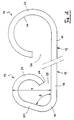
- the sheet pile with complementary open side loops has the particularity of having a male loop and a female loop formed on the same side of the sheet during the profiling operation, and such as the openings (36) and (37). loops, female and male respectively, face each other.
- a female loop (14) and a male loop (15) are formed on the longitudinal edges of the sheet metal, the profiles of which are conjugate and complementary.
- the profile of the female loop extends from the part (16) of the core (17) which borders it, in a rounding (22) over approximately 3/4 of a circle.
- the profile of the male loop (15) forms a first rounded (19) slightly greater than 1/4 of a circle, extended by a flat (20) - even extended by a second round (21) extending over approximately 5/8 of a circle.
- the loops (14) and (15) cooperate mainly by the rounding of the female loop and by the second rounding of the male loop. Consequently, the outside radius of the second rounding (21) of the male loop (15) is slightly less than or at most equal, apart from the clearance, the inside radius of the rounding (22) of the female loop (14).
- the male loop (15) is placed overhanging the end (18) of the core (17) with a height (H) equal to approximately 103% of the inside diameter of the rounding of the female loop. .
- each sheet pile (13) also has on its core (17) a longitudinal fold line (23), produced by example either using rollers, during the last stages of the operation of profiling the loops (14) and (15), or using any suitable tool, for example a profiler, rollers, or a folder placed immediately downstream of the profiling line.
- a longitudinal fold line (23) produced by example either using rollers, during the last stages of the operation of profiling the loops (14) and (15), or using any suitable tool, for example a profiler, rollers, or a folder placed immediately downstream of the profiling line.
- the fold (23) extends parallel to the loops (14) and (15) and in addition forms a dihedral with a constant angle; according to another of the features of the invention, the angle ⁇ of this dihedral is obtuse and open in the direction of the loops (14) and (15).
- the acute angle ⁇ formed by the flat (20) of the male loop (15) with the core (17) of the sheet pile (13) and the obtuse angle ⁇ which the core (17) of on either side of its fold (23) are additional.
- the plate (20) and the part (16) of the core (17) which borders the female loop (14) are parallel.
- the sheet metal thus profiled has an overall width of 854 mm, the distance separating in projection onto the core (17) the center of the rounding of the female loop (14) and the center of the first rounding (19) of the loop male (15) being 802 mm.
- the sheet thus profiled is folded at the level of its core so as to form a fold (23) open by 105 ° in the direction of the two loops (14) and (15 ).
- the fold (23) can be formed longitudinally in any which point of the core (17) located between the loops (14) and (15), while respecting a minimum height of 10 mm for the part (16) (or for the part (18)) separating the fold (23 ) of the nearest loop (14) (or respectively (15)), so as to allow easy handling of the folded sheet pile and threshing of this sheet pile.
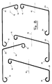
- FIG. 8 shows five profiled and folded sheet piles according to the above example, said sheet piles each distinguished by the position of their fold (23) relative to the loops (14) and (15).
- the construction of a curtain from the sheet piles (13) of the invention is obtained by engaging said sheet pile head to tail, as it appears in the overall representation of Figure 7. After threshing of a first sheet pile, for example the one shown hatched, the construction of the curtain is started by associating with this first sheet pile a sheet pile (13) of the same configuration, which is turned 180 ° so as to penetrate the male loop (15) of the second sheet pile in the female loop (14) of the first sheet pile.
- the male buckle-female buckle nesting is characterized in that, after engagement, the loops (14) and (15) have at least three contact zones between them.
- a perfectly closed longitudinal chamber (28) is formed between two female (14) and male (15) loops, in which one can therefore inject a sealant, such as a cement or a resin.
- a sealant such as a cement or a resin.
- the implementation of sheet piles according to the invention therefore allows an injection of sealant without any waste.
- section of the chamber (28) is such that, if necessary, it allows the introduction into each engagement male buckle-female loop of a bar or a reinforcing tube allowing to further improve the resistance characteristics of the curtain formed from sheet piles (13) interlocked head to tail.
- the sheet pile (13) has another advantage inherent in the profiles given to the loops (14) and (15).
- the lock constituted by a male loop fitted into a female loop is movable in rotation about a longitudinal axis below its engagement position concretized by its contacting of the above three areas.
- the authorized ⁇ travel is of the order of 38 °, as shown in Figure 6.
- the sheet pile to be beaten can indeed occupy any position between that shown in dashed lines in FIG. 6 and that shown in solid lines in the same figure, which both constitute the limit positions of the male loop inside the female loop. It is only at the end of threshing that the second sheet pile is pivoted and brought to its ideal engagement position, shown in solid lines, as shown by the arrows (30), until the contacting of the male loop and the female loop by the three zones which characterize the engagement as it was seen previously.
- a variant (113) of the aforementioned sheet pile (13) has been shown in FIGS. 9 to 11, a variant which constitutes the upper limit of the various configurations which can be given to the male loop-female loop assembly of the sheet pile. (13) since, apart from play, the outside radius of the second rounding (121) of the male loop (115) is equal to the inside radius of the rounding (122) of the female loop (114).
- the contact during the fitting of the male mouth (115) - female mouth (114), visible in detail in FIG. 10, takes place at the rounded points (121) and (122), by the intermediate plate ( 120) of the male loop bearing on the part (116) of the core (117) of the sheet pile which borders the female loop and by the end (127) of the female mouth bearing on the part (118) of the soul that borders the male mouth.
- the advantages of the sheet pile (113) over the sheet pile (13) are essentially of two types: the tightness at each socket is improved, since the areas in contact are more extensive, and the chamber (128) is of a noticeably higher section, allowing greater reinforcement.
- the disadvantage of the sheet pile (113) relative to the sheet pile (13) lies in that the interlocking can only be carried out in one position, that of the engagement, and that it is not possible to rotate the second sheet pile during threshing relative to the first sheet pile already in place.
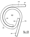
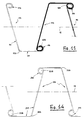
- FIGS. 12 to 14 A third variant of sheet pile (213) according to the invention has been shown in FIGS. 12 to 14, a variant in which the profile of the male loop (215) extends in a rounded shape (233) over at least 3/4 of circle and the profile of the female loop (214) forms a rounding (234) on at least 1/2 circle and is extended by a flat (235).
- the outside radius of the rounding (233) is at play almost advantageously equal to the inside radius of the rounding (234).
- the acute angle ⁇ formed by the flat (235) of the female loop with the part (216) of the core (217) which borders said female loop and the obtuse angle ⁇ presented by the core (217 ) on either side of its fold line (223) are additional.
- the flat (235) is formed at the end of the round (234) so that the overall width ( L ) of the female loop (214) is equal to the outside diameter of the male loop (233).
- the engagement male buckle-female loop shown in detail in Figure 13 is characterized in that said loops are in contact by the rounded (233) and (234) and by the flat (235) of the female loop resting on the part (218) of the core (217) which borders the male loop.
- the sheet pile (213) has the advantages of ensuring the formation of a completely sealed lock and a chamber (228) of a large section which allows the introduction into each lock of large tubes or reinforcing bars. On the other hand, it is not possible to rotate a sheet pile during threshing relative to the sheet pile in which it is fitted.
- any sheet pile (13, 113, 213) can be easily shaped to form an angle in a non-straight sheet pile wall.
- a special sheet pile is made, called a "corner sheet pile" from which a portion of non-curtain can extend. aligned with the first portion of the curtain ended by said corner sheet pile.
Landscapes
- Engineering & Computer Science (AREA)
- Structural Engineering (AREA)
- Chemical & Material Sciences (AREA)
- Composite Materials (AREA)
- Life Sciences & Earth Sciences (AREA)
- General Life Sciences & Earth Sciences (AREA)
- Mining & Mineral Resources (AREA)
- Paleontology (AREA)
- Civil Engineering (AREA)
- General Engineering & Computer Science (AREA)
- Bulkheads Adapted To Foundation Construction (AREA)
- Coating With Molten Metal (AREA)
Claims (16)
- Verfahren zum Herstellen einer Metallspundbohle (13,113, 213), die zwei seitliche, offene, komplementäre Wülste aufweist, die durch einen nicht ebenen mittleren Steg miteinander verbunden sind und von denen die eine Wulst eine "Aufnahmewulst" (14,114,214) und die andere Wulst eine "Einsteckwulst" (15,115,215) ist und die durch einen Profilierungsvorgang jeweils an einem Längsrand eines Metallblechs auf derselben Seite des Blechs und derart ausgebildet werden, daß ihre Öffnungen (37,36) sich gegenüberstehen, dadurch gekennzeichnet, daS am Ende oder nach diesem Profilierungsvorgang der Steg (17,117,217) des Blechs in einer einzigen Linie (23,123,223) gefaltet wird, die sich in Längsrichtung und parallel zu den Wülsten erstreckt, sodaß der Steg einen Flächenwinkel bildet, dessen eingeschlossener Winkel α stumpf und in Richtung der Wulstöffnungen offen ist.
- Profilierte Metallspundbohle mit zwei seitlichen, offenen, komplementären Wülsten, nämlich einer Aufnahmewulst und einer Einsteckwulst, die durch einen nicht ebenen mittleren Steg miteinander verbunden sind, welche Spundbohle (13,113,213) nach dem Verfahren gemäß Anspruch 1 hergestellt ist und dazu bestimmt ist, durch Aneinanderreihung mit anderen Spundbohlen unter gegenseitigem Eingriff der zwei Wülste jeder Spundbohle mit der komplementären Wulst jeder benachbarten Spundbohle eine Spundwand, namentlich eine Spundwand mit starkem Widerstandsmodul herzustellen, wobei die Einsteckwulst (15,115,215) und die Aufnahmewulst (14,114,214) auf derselben Seite des Steges (17,117,217) angeordnet sind und die Spundbohle dadurch gekennzeichnet ist, daß der genannte Steg eine einzige Längsfaltlinie (23,123,223) aufweist, die sich parallel zu den Wülsten erstreckt, sodaß der Steg einen Flächenwinkel bildet, dessen Öffnungswinkel α stumpf und in Richtung der Wulstöffnungen (37, 36) offen ist.
- Spundbohle nach Anspruch 2, dadurch gekennzeichnet, daß die beiden Einsteck- und Aufnahmewülste (15,115,215;14,114,214) derart konjugiert profiliert sind, daß nach ihrem Ineingriffbringen mit einer entsprechenden komplementären Wulst einer benachbarten Spundbohle (13,113,213) jede Ineinaderfügung von Einsteckwulst und Aufnahmewulst wenigstens drei Berührungszonen aufweist.
- Spundbohle nach einem der Ansprüche 2 und 3, dadurch gekennzeichnet, daß das Profil der Aufnahmewulst (14,114) sich in einem Bogen (22,122) über etwa 3/4 eines Kreises erstreckt und das Profil der Einsteckwulst (15,115) einen ersten Bogen (19, 119) von etwas mehr als 1/4 eines Kreises bildet, gefolgt von einer Abflachung (20,120), der wiederum ein zweiter Bogen (21, 121) folgt, der sich über etwa 5/8 eines Kreises streckt.
- Spundbohle nach Anspruch 4, dadurch gekennzeichnet, daß der spitze Winkel β , den die Abflachung (20,120) der Einsteckwulst (15,115) mit dem Steg (17,117) der Spundbohle bildet, und der stumpfe Winkel α , den der Steg beiderseits seiner Faltlinie (23,123) aufweist, zusammen 180° ergeben.
- Spundbohle nach einem der Ansprüche 4 und 5, dadurch gekennzeichnet, daß der Außenradius des zweiten Bogens (121) der Einsteckwulst (115) unter Berücksichtigung von geringem Spiel etwa gleich dem Innenradius des Bogens (122) der Aufnahmewulst (114) ist, sodaß die Berührung der Ineinanderfügung von Einsteckwulst und Aufnahmewulst sich an diesem Bögen (121,122), an der Zwischenabflachung (120) der Einsteckwulst in Anlage an dem an die Aufnahmewulst angrenzenden Abschnitt (116) des Steges (117) der Spundbohle (113) und an dem Ende (127) der Aufnahmewulst in Anlage an dem an die Einsteckwulst angrenzenden Stegabschnitt (118) der Spundbohle vollzieht.
- Spundbohle nach einem der Ansprüche 4 und 5, dadurch gekennzeichnet, daß der Außenradius des zweiten Bogens (21) der Einsteckwulst (15) etwas kleiner als der Innenradius des Bogens (22) der Aufnahmewulst (14) ist, sodaß die Berührung der Ineinanderfügung von Einsteckwulst und Aufnahmewulst sich an dem am weitesten außen liegenden Punkt (24) der Einsteckwulst in Anlage an einem Punkt (25) der Innenwand (26) des Bogens (22) der Aufnahmewulst, an der Zwischenabflachung (20) der Einsteckwulst in Anlage an dem an die Aufnahmewulst angrenzenden Abschnitt (16) des Steges (17) der Spundbohle (13) und an dem Ende (27) der Aufnahmewulst in Anlage an dem an die Einsteckwulst angrenzenden Stegabschnitt (18) der Spundbohle vollzieht.
- Spundbohle nach Anspruch 7, dadurch gekennzeichnet, daß der Außenradius des zweiten Bogens (21) der Einsteckwulst (15) im Bereich von 85/100 bis 95/100 des Innenradius des Bogens (22) der Aufnahmewulst (14) liegt.
- Spundbohle nach einem der Ansprüche 7 und 8, dadurch gekennzeichnet, daß die Breite der Zwischenabflachung (20) der Einsteckwulst (15) etwa gleich 5/6 des Außenradius des zweiten Bogens (21) der Einsteckwulst ist.
- Spundbohle nach einem der Ansprüche 7 bis 9, dadurch gekennzeichnet, daß der Innenradius des ersten Bogens (19) der Einsteckwulst (15) im wesentlichen halb so groß wie derAußenradius des zweiten Bogens (21) der Einsteckwulst ist.
- Spundbohle nach Anspruch 3, dadurch gekennzeichnet, daß das Profil der Einsteckwulst (215) sich in einem Bogen (233) über wenigstens 3/4 eines Kreises erstreckt und das Profil der Aufnahmewulst (214) einen Bogen von wenigstens einem Halbkreis bildet, dem eine Abflachung (235) folgt.
- Spundbohle nach Anspruch 11, dadurch gekennzeichnet, daß der spitze Winkel δ , den die Abflachung (235) der Aufnahmewulst (214) mit dem Spundbohlensteg (216) bildet, und der stumpfe Winkel α , den der Steg (217) in seiner Faltlinie (223) aufweist, zusammen 180° sind.
- Spundbohle nach einem der Ansprüche 11 und 12, dadurch gekennzeichnet, daß die Abflachung (235) am Ende des Bogens (234) derart ausgebildet ist, daß die Gesamtbreite der Aufnahmewulst (214) gleich dem Außendurchmesser der Einsteckwulst (233) ist.
- Spundbohle nach einem der Ansprüche 11 bis 13, dadurch gekennzeichnet, daß der Außenradius des Bogens (233) der Einsteckwulst (215) unter Berücksichtigung geringen Spiels etwa gleich dem Innenradius des Bogens (234) der Aufnahmewulst (214) ist, sodaß die Berührung der Ineinanderfügung von Einsteckwulst und Aufnahmewulst sich an diesen Bögen (233,234) und an der Abflachung (235) der Aufnahmewulst in Anlage an dem an die Einsteckwulst angrenzenden Abschnitt (218) des Spundbohlensteges (217) vollzieht.
- Spundbohle nach einem der Ansprüche 2 bis 13, dadurch gekennzeichnet, daß der Winkel α des Flächendreiecks, den der Steg (17,117,217) in seiner Faltlinie (23,123,223) bildet, bei etwa 105° liegt.
- Spundwand, dadurch gekennzeichnet, daß sie im wesentlichen aus Spundbohlen (13,113,213) nach einem der Ansprüche 2 bis 15 besteht, die ineinandergefügt sind, wobei jeweils die Einsteck- und Aufnahmewülste (15,115,215;14,114,214) jeder Spundbohle der Spundwand zu beiden Seiten von deren neutraler Achse (12) liegen.
Priority Applications (1)
| Application Number | Priority Date | Filing Date | Title |
|---|---|---|---|
| AT88402785T ATE101221T1 (de) | 1987-11-06 | 1988-11-04 | Profilierte spundbohlen mit komplementaeren, seitlich offenen schlosshaken, und aus diesen spundbohlen zusammengesetzte spundwaende. |
Applications Claiming Priority (2)
| Application Number | Priority Date | Filing Date | Title |
|---|---|---|---|
| FR8715460 | 1987-11-06 | ||
| FR8715460A FR2622908B1 (fr) | 1987-11-06 | 1987-11-06 | Palplanches metalliques profilees a boucles laterales ouvertes complementaires,et rideaux constitues a partir desdites palplanches |
Publications (2)
| Publication Number | Publication Date |
|---|---|
| EP0315548A1 EP0315548A1 (de) | 1989-05-10 |
| EP0315548B1 true EP0315548B1 (de) | 1994-02-02 |
Family
ID=9356595
Family Applications (1)
| Application Number | Title | Priority Date | Filing Date |
|---|---|---|---|
| EP88402785A Expired - Lifetime EP0315548B1 (de) | 1987-11-06 | 1988-11-04 | Profilierte Spundbohlen mit komplementären, seitlich offenen Schlosshaken, und aus diesen Spundbohlen zusammengesetzte Spundwände |
Country Status (4)
| Country | Link |
|---|---|
| EP (1) | EP0315548B1 (de) |
| AT (1) | ATE101221T1 (de) |
| DE (1) | DE3887633D1 (de) |
| FR (1) | FR2622908B1 (de) |
Families Citing this family (7)
| Publication number | Priority date | Publication date | Assignee | Title |
|---|---|---|---|---|
| GB2293189B (en) * | 1994-09-13 | 1998-03-25 | David Murray | Trench sheet |
| CA2466537A1 (en) * | 2002-02-14 | 2003-08-21 | Chin Chai Ong | Connector |
| NL1033195C2 (nl) * | 2007-01-09 | 2008-07-10 | Halteren Infra B V Van | Damwand, damwandprofiel, slotorgaan en werkwijzen voor een dergelijke damwand. |
| CN106870903A (zh) * | 2015-12-14 | 2017-06-20 | 苏州耀洲金属制品有限公司 | 成品支架 |
| CN109502136A (zh) * | 2018-12-03 | 2019-03-22 | 山东金都消防设备有限公司 | 一种可拆卸箱体及其运输方法 |
| CN113167044A (zh) * | 2018-12-07 | 2021-07-23 | 欧领特私人有限公司 | 板桩联锁机构 |
| US11243012B2 (en) * | 2019-11-11 | 2022-02-08 | Clifford Grove | Portable heat shield assembly |
Family Cites Families (6)
| Publication number | Priority date | Publication date | Assignee | Title |
|---|---|---|---|---|
| FR548221A (fr) * | 1922-02-07 | 1923-01-10 | Perfectionnements aux cloisons en palplanches métalliques | |
| US1894012A (en) * | 1931-02-05 | 1933-01-10 | Julius R Wemlinger | Corrugated sheet piling |
| GB417773A (en) * | 1933-07-27 | 1934-10-11 | Fried Krupp Ag Friedrich Alfre | Improvements in or relating to sheet metal piles |
| US2880589A (en) * | 1955-01-25 | 1959-04-07 | Acme Steel Co | Sheet metal piling |
| BE759798A (fr) * | 1969-12-06 | 1971-05-17 | Krupp Ag Huettenwerke | Palplanche |
| GB1602597A (en) * | 1978-03-22 | 1981-11-11 | Mabey Hire Co | Steel sheet piling |
-
1987
- 1987-11-06 FR FR8715460A patent/FR2622908B1/fr not_active Expired - Fee Related
-
1988
- 1988-11-04 DE DE88402785T patent/DE3887633D1/de not_active Expired - Lifetime
- 1988-11-04 EP EP88402785A patent/EP0315548B1/de not_active Expired - Lifetime
- 1988-11-04 AT AT88402785T patent/ATE101221T1/de not_active IP Right Cessation
Also Published As
| Publication number | Publication date |
|---|---|
| FR2622908A1 (fr) | 1989-05-12 |
| FR2622908B1 (fr) | 1990-02-02 |
| DE3887633D1 (de) | 1994-03-17 |
| EP0315548A1 (de) | 1989-05-10 |
| ATE101221T1 (de) | 1994-02-15 |
Similar Documents
| Publication | Publication Date | Title |
|---|---|---|
| CA2991429C (fr) | Insert de moulage et bloc de parement avec un tel insert | |
| EP0231978B1 (de) | Baublock und mit diesem Block hergestellte Konstruktion | |
| EP0315548B1 (de) | Profilierte Spundbohlen mit komplementären, seitlich offenen Schlosshaken, und aus diesen Spundbohlen zusammengesetzte Spundwände | |
| EP3564459A1 (de) | Modul mit wabenstruktur und dieses umfassendes abdecksystem | |
| WO2004007860A1 (fr) | Element de construction | |
| EP0028558B1 (de) | Verfahren zum Verbessern des Gleitwiderstandes von einer Baukonstruktion und ihre Fundierung | |
| EP0247054B1 (de) | Metallspundwandbohlen, kaltgeformt durch profilierung oder biegung eines metallbleches und wände, gebildet durch diese bohlen | |
| FR2550568A3 (fr) | Element modulaire de construction maconnee | |
| BE1027537A1 (fr) | Module préfabriqué pour la construction d’un mur ou d’un muret habillé de pierres naturelles empilées façon pierres sèches | |
| FR2721988A1 (fr) | Conduite de circulation de fluide | |
| FR2506367A1 (fr) | Bloc de beton en forme de l et procede de construction d'un mur de soutenement utilisant lesdits blocs de beton en forme de l | |
| FR2816647A1 (fr) | Parement pour ouvrage en terre renforcee | |
| FR2724681A1 (fr) | Panneau formant coffrage perdu pour la construction d'ouvrages de genie civil, et notamment de piscines et procede de mise en oeuvre de ces panneaux | |
| EP1004717B1 (de) | Hohlbausteinsatz | |
| EP0224012A2 (de) | Verfahren zum Herstellen von Wänden für Bauelemente und Gebäude und Baublöcke für dieses Verfahren | |
| FR2675233A1 (fr) | Element tubulaire prefabrique. | |
| FR2807456A1 (fr) | Dispositif de soutenement et/ou de stabilisation de mur, merlon, talus | |
| FR2707683A1 (fr) | Bloc de construction évidé intérieurement, destiné à recevoir un coulis durcissable. | |
| EP2453067B1 (de) | Verlorene Schalungsplatte und verlorener Schalungsblock, der eine solche Platte enthält | |
| FR2601432A1 (fr) | Tubes ou viroles prefabriques | |
| EP1672124A2 (de) | Verfahren zur Herstellung von Schlitzwänden | |
| EP0273077B1 (de) | Stützbauwerk und Verfahren zum Verwirklichen dieses Stützbauwerks | |
| BE524731A (de) | ||
| WO2018065528A1 (fr) | Nappe géosynthétique alvéolaire pour la construction d'un ouvrage en sol renforcé et ouvrage comprenant une telle nappe | |
| FR2795110A1 (fr) | Coffrage isolant pour la realisation d'un mur en beton |
Legal Events
| Date | Code | Title | Description |
|---|---|---|---|
| PUAI | Public reference made under article 153(3) epc to a published international application that has entered the european phase |
Free format text: ORIGINAL CODE: 0009012 |
|
| AK | Designated contracting states |
Kind code of ref document: A1 Designated state(s): AT BE CH DE ES GB GR IT LI LU NL SE |
|
| 17P | Request for examination filed |
Effective date: 19891023 |
|
| 17Q | First examination report despatched |
Effective date: 19901112 |
|
| GRAA | (expected) grant |
Free format text: ORIGINAL CODE: 0009210 |
|
| AK | Designated contracting states |
Kind code of ref document: B1 Designated state(s): AT BE CH DE ES GB GR IT LI LU NL SE |
|
| PG25 | Lapsed in a contracting state [announced via postgrant information from national office to epo] |
Ref country code: IT Free format text: LAPSE BECAUSE OF FAILURE TO SUBMIT A TRANSLATION OF THE DESCRIPTION OR TO PAY THE FEE WITHIN THE PRE;WARNING: LAPSES OF ITALIAN PATENTS WITH EFFECTIVE DATE BEFORE 2007 MAY HAVE OCCURRED AT ANY TIME BEFORE 2007. THE CORRECT EFFECTIVE DATE MAY BE DIFFERENT FROM THE ONE RECORDED.SCRIBED TIME-LIMIT Effective date: 19940202 Ref country code: NL Effective date: 19940202 Ref country code: SE Effective date: 19940202 Ref country code: DE Effective date: 19940202 Ref country code: GR Free format text: LAPSE BECAUSE OF FAILURE TO SUBMIT A TRANSLATION OF THE DESCRIPTION OR TO PAY THE FEE WITHIN THE PRESCRIBED TIME-LIMIT Effective date: 19940202 Ref country code: ES Free format text: THE PATENT HAS BEEN ANNULLED BY A DECISION OF A NATIONAL AUTHORITY Effective date: 19940202 Ref country code: GB Effective date: 19940202 Ref country code: AT Effective date: 19940202 |
|
| REF | Corresponds to: |
Ref document number: 101221 Country of ref document: AT Date of ref document: 19940215 Kind code of ref document: T |
|
| REF | Corresponds to: |
Ref document number: 3887633 Country of ref document: DE Date of ref document: 19940317 |
|
| NLV1 | Nl: lapsed or annulled due to failure to fulfill the requirements of art. 29p and 29m of the patents act | ||
| GBV | Gb: ep patent (uk) treated as always having been void in accordance with gb section 77(7)/1977 [no translation filed] |
Effective date: 19940202 |
|
| PG25 | Lapsed in a contracting state [announced via postgrant information from national office to epo] |
Ref country code: LU Free format text: LAPSE BECAUSE OF NON-PAYMENT OF DUE FEES Effective date: 19941130 Ref country code: LI Effective date: 19941130 Ref country code: BE Effective date: 19941130 Ref country code: CH Effective date: 19941130 |
|
| PLBE | No opposition filed within time limit |
Free format text: ORIGINAL CODE: 0009261 |
|
| STAA | Information on the status of an ep patent application or granted ep patent |
Free format text: STATUS: NO OPPOSITION FILED WITHIN TIME LIMIT |
|
| 26N | No opposition filed | ||
| BERE | Be: lapsed |
Owner name: PROFILES ET TUBES DE L'EST Effective date: 19941130 |
|
| REG | Reference to a national code |
Ref country code: CH Ref legal event code: PL |