EP0315738A2 - System zur automatischen Zählerprüfung und -eichung - Google Patents
System zur automatischen Zählerprüfung und -eichung Download PDFInfo
- Publication number
- EP0315738A2 EP0315738A2 EP88112603A EP88112603A EP0315738A2 EP 0315738 A2 EP0315738 A2 EP 0315738A2 EP 88112603 A EP88112603 A EP 88112603A EP 88112603 A EP88112603 A EP 88112603A EP 0315738 A2 EP0315738 A2 EP 0315738A2
- Authority
- EP
- European Patent Office
- Prior art keywords
- liquid
- volume
- calibration
- meter
- dispenser
- Prior art date
- Legal status (The legal status is an assumption and is not a legal conclusion. Google has not performed a legal analysis and makes no representation as to the accuracy of the status listed.)
- Withdrawn
Links
Images


Classifications
-
- B—PERFORMING OPERATIONS; TRANSPORTING
- B67—OPENING, CLOSING OR CLEANING BOTTLES, JARS OR SIMILAR CONTAINERS; LIQUID HANDLING
- B67D—DISPENSING, DELIVERING OR TRANSFERRING LIQUIDS, NOT OTHERWISE PROVIDED FOR
- B67D7/00—Apparatus or devices for transferring liquids from bulk storage containers or reservoirs into vehicles or into portable containers, e.g. for retail sale purposes
- B67D7/06—Details or accessories
- B67D7/08—Arrangements of devices for controlling, indicating, metering or registering quantity or price of liquid transferred
- B67D7/085—Testing or calibrating apparatus therefore
-
- G—PHYSICS
- G01—MEASURING; TESTING
- G01F—MEASURING VOLUME, VOLUME FLOW, MASS FLOW OR LIQUID LEVEL; METERING BY VOLUME
- G01F25/00—Testing or calibration of apparatus for measuring volume, volume flow or liquid level or for metering by volume
- G01F25/10—Testing or calibration of apparatus for measuring volume, volume flow or liquid level or for metering by volume of flowmeters
- G01F25/11—Testing or calibration of apparatus for measuring volume, volume flow or liquid level or for metering by volume of flowmeters using a seal ball or piston in a test loop
Definitions
- the present invention relates generally to liquid dispensing devices and methods, and more particularly to such devices and methods wherein a mechanical flow meter is used to measure the volume of liquid dispensed.
- meters in liquid dispensing devices have been provided with means to change the displacement thereof so that the volume of liquid dispensed per rotation of the meter shaft corresponds in fixed relation to the number of delivery pulses produced and, therefore, the volume displayed by the data display means.
- This procedure involving mechanical calibration of the meter to alter the meter output entails not only the expense of a variable displacement meter, but also requires an attendant to manually perform multiple dispensing operations and make adjustments to the meter to arrive at the proper setting.
- Another method of calibrating a meter involves the use of large calibration barrels and barrel meter provers.
- the barrels are either permanently connected directly to the pipeline by means of elaborate valving, or are carried on a vehicle and temporarily attached inline of the flow of the pipeline, in order to monitor the output of the flow meter over dispensation of a fixed volume of liquid.
- a meter factor is then manually calculated and manually applied to all indicated readings from the meter.
- An electronic register/calibrator apparatus is commercially available for use in a bulk flow application and includes a meter and a pulser, wherein a calibration factor is manually entered on thumbwheel switches for use to modify the pulser output prior to its use by the electronic register to reflect the accumulated volume of liquid flowing through the meter. Similar to the previously described procedure of mechanically calibrating the meter in a liquid dispensing device, calculation of the manually entered correction factor for use by the electronic register also requires an attendant to perform calibrated flow measurements and manually calculate the appropriate correction factor to be entered.
- Another disadvantage of known meter calibration methods is that each time a meter is replaced or repaired, the time and expense of conducting a conventional meter calibration test is incurred.
- a still further disadvantage of meter calibration methods involving the calculation of meter correction factors is that, as new factors are calculated, a records problem is created in maintaining the most current data.
- the present invention overcomes the aforementioned problems and disadvantages of prior art meter proving systems by providing an apparatus for and method of calibrating a mechanical flow meter used in a liquid dispenser, wherein a calibration factor for correcting the number of delivery pulses generated by the meter and pulser is automatically calculated during normal dispensing operation of the liquid dispenser apparatus.
- the present invention provides for the dispensation of a calibrated volume of liquid during which a plurality of delivery pulses in direct proportion to the volume of liquid passed through the meter are accumulated and compared to a constant value representing the number of pulses desired as an input for electronic data display means to reflect dispensation of the calibrated volume.
- a calibration factor is automatically calculated and used to modify the delivery pulses for use as input pulses to the data display means in order to accurately reflect the volume of liquid being dispensed.
- a primary advantage of a liquid dispenser apparatus having meter calibration in accordance with the present invention is that meter calibration is performed automatically without human input or supervision.
- Another advantage of the present invention is that meter calibration is performed automatically during normal dispensing operations of the liquid dispenser apparatus.
- Still another advantage of a liquid dispenser apparatus according to the present invention is that a flow meter becomes virtually self-calibrating over the life of the meter.
- a further advantage of the present invention is that the need is eliminated for expensive meters having mechanical variable displacement.
- Yet another advantage of the present invention is that meter calibration in a liquid dispensing application is performed more frequently at less expense.
- a still further advantage of the present invention is that meter calibration is less cumbersome and requires less space for implementation.
- a yet further advantage of the present invention is that calibration accuracy is improved by the provision of multiple runs of a single calibrated volume.
- the invention in one form thereof, provides a liquid dispenser apparatus comprising a liquid volume measuring means for providing a raw output signal in proportion to a volume of liquid flowing therethrough.
- the dispenser apparatus also includes means for indicating the start and finish of flow of a calibrated volume of liquid through the liquid measuring means.
- signal measuring means are provided for measuring the raw output signal during flow of the calibrated volume of liquid.
- the signal measuring means are responsive to the means for indicating the start and finish of the flow of the calibrated volume.
- Signal modifying means responsive to the raw output signal measurement, is provided for modifying the raw output signal as a function of the calibrated volume and the raw output signal measurement. Accordingly, the signal modifying means provides a calibrated signal.
- the invention further provides, in one form thereof, a liquid dispenser apparatus comprising a liquid measuring means for providing an output signal in correlation with a volume of dispensed liquid.
- the output signal is variable due to variations of the measuring means.
- the liquid dispenser apparatus further includes data display means for reflecting the volume of liquid dispensed.
- the data display means is responsive to an input signal.
- calibration means for determining a correction factor by which to modify the output signal to generate the input signal to the data display means.
- the correction factor is automatically determined at predetermined dispenser operating intervals to provide correction of the variable output signal. Accordingly, the data display means accurately reflects the volume of liquid dispensed despite the variations of the liquid measuring means.
- the invention further provides, in one form thereof, a method of calibrating a measuring means in a liquid dispensing apparatus.
- the liquid dispensing apparatus includes, within a housing, mechanical flow measuring means for producing a rotary output in response to the passage of liquid therethrough. Connected to the rotary output of the measuring means is a delivery pulser means for producing a plurality of output delivery pulses in proportion to the volume of liquid dispensed.
- the dispensing apparatus includes data display means responsive to input pulses for reflecting a volume of liquid dispensed in direct proportion to the number of input pulses received. The proportion of output delivery pulses produced by the pulser means to the volume of the liquid dispensed varies according to mechanical wear and variations of the measuring means.
- the calibration method is directed to calibrating the measuring means to compensate for the variations in the proportion of output delivery pulses produced to the volume of liquid dispensed.
- the calibration method includes, in one form thereof, the step of providing indicating means within the housing for indicating the initiation of and completion of dispensation of a calibrated volume of liquid.
- the number of input pulses necessary for the data display means to reflect the calibrated volume is a known constant.
- a further step is accumulating the output delivery pulses during dispensation of liquid beginning with the initiation indication and ending with the completion indication.
- a further step provides for comparing the known constant to the accumulation of the delivery pulses to determine a meter correction factor.
- the method provides for modifying the output delivery pulses by the meter correction factor for use as input pulses to the data display means.
- the invention further provides, in one form thereof, a liquid dispenser apparatus comprising a manually operable nozzle, a valve, a pump, a mechanical flow meter, delivery pulser, value display, calibration means, an accumulator, and computer.
- the valve controls dispensing of liquid and the pump supplies a flow of liquid to the valve.
- the meter produces a meter output in proportion to the dispensed volume of liquid passing through the meter, whereby the dispensed volume of liquid for a given meter output is variable due to mechanical wear and variations of the flow meter.
- the pulser is responsive to the meter output of the flow meter, and produces a plurality of output delivery pulses in direct proportion to the meter output.
- the value display is responsive to input pulses for reflecting a volume value in direct proportion to the number of input pulses received. This proportion represents a display constant.
- the calibration means includes a calibration chamber of a predetermined calibrated volume for use in indicating dispensation of a volume of liquid substantially equal to the calibrated volume.
- the accumulator accumulates the output delivery pulses during dispensation of the volume of liquid substantially equal to the calibrated volume.
- the computer automatically computes a calibration factor based upon the number of delivery pulses accumulated during dispensation of the calibrated volume, the display constant of the value display, and the calibrated volume. More specifically, the calibration factor is the raw number of delivery pulses accumulated during dispensation of the calibrated volume divided into the desired number of delivery pulses required by the value display to display the calibrated volume.
- the output delivery pulses are then modified by the calibration factor before being supplied as input pulses to the value display.
- the meter is automatically compensated for variations in the meter output caused by mechanical wear and variations of the flow meter. Accordingly, the value display reflects an accurate value for the volume of liquid dispensed.
- the invention still further provides, in one form thereof, a liquid fuel dispensing apparatus comprising a housing.
- liquid measuring means and proving means for proving the amount of fuel dispensed in a predetermined number of dispensing operations of the apparatus.
- the liquid fuel dispenser also includes display means for displaying the volume of dispensed fuel and means for calibrating the display means based on the proving means.
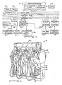
- dispenser 10 includes a housing 12 comprising an upper portion 13 and a lower portion 14. Housing 12 is situated on a base 15 beneath which is located a liquid storage tank 16. Within housing 12 are located a liquid pump 18 and a mechanical liquid flow meter 20. In the usual manner of operating dispenser 10 in the absence of the present invention, pump 18 pumps liquid from tank 16 to meter 20 through conduit length 19. From meter 20, the liquid is delivered to a nozzle valve 22 located externally of housing 12. Actuation of valve 22 controls dispensation of the liquid from dispenser 10.
- liquid fuel dispenser 10 is a TCS Model 324 dispenser manufactured by Tokheim Corporation, Fort Wayne, Indiana.
- pump 18 comprises a rotary pump and air separator Model 855
- meter 20 comprises a positive displacement type meter Model 898-K, both manufactured by Tokheim Corporation.
- Rotary pump 18 is operated by a conventional electric motor (not shown).
- a handle switch 30 is manually operable, such as by lifting a handle, to initiate a new dispensing event.
- a reset switch 32 located on the housing or at a remote location therefrom, is operable by an attendant to reset display unit 26 and to enable initiation of a new dispensing event by operation of handle switch 30.
- an automatic meter proving and calibration system 28 may be incorporated into fuel dispenser 10 with a minimal amount of modification to existing components. Specifically, conduit length 19 through which liquid is ordinarily pumped is disconnected and the pumped liquid is instead channeled through system 28. Likewise, the direct connection normally present between pulser 24 and display unit 26 is removed, and pulser 24 instead delivers raw pulses directly to system 28 for modification before delivery to display unit 26. System 28 also requires an input from handle switch 30.
- Automatic meter proving and calibration system 28 in accordance with one form of the present invention, includes an electronic control unit (ECU) 34, a prover assembly 36, a set of thumbwheel switches 38, and valving means, such as a conventional solenoid actuated four-way, two-position valve 40.
- ECU electronice control unit
- prover assembly 36 When system 28 is installed, valve 40 is connected between pump 18 and meter 20 within housing 12. Valve 40 is electrically controlled by ECU 34 to introduce prover assembly 36 in series with the flow of liquid from pump 18 to meter 20. In the preferred embodiment as illustrated, valve 40 provides means for reversing the flow of liquid through prover assembly 36 without changing direction of flow through meter 20.
- Prover assembly 36 is a conventional volumetric tube prover comprising a calibrated barrel in the form of a cylindrical tube 42 having a plunger or piston member 44 movable therein from one end of tube 42 to the other in response to bidirectional flow of liquid through tube 42 as controlled by valve 40.
- a pair of spaced apart sensors, such as proximity switches 46 and 48, provide a gate signal to ECU 34 whenever piston or plunger 44 achieves a position adjacent to either of switches 46 and 48.
- switches 46 and 48 are positioned on tube 42 at a distance from one another so as to establish a predetermined calibrated volume of liquid between the positions wherein plunger 44 is adjacent one switch 46 and the other switch 48.
- thumbwheel switches 38 provide binary coded decimal (BCD) information to ECU 34 indicative of an experimentally determined volume of liquid in tube 42 between switches 46 and 48.
- BCD binary coded decimal
- prover assembly 36 comprises a volumetric tube prover having a tube 42 which may be oriented vertically as shown in Figs. 1 and 5, or at any angular orientation necessary to facilitate mounting within housing 12.
- tube 42 is approximately two inches in diameter and six inches long. However, it is recognized that the dimensions of tube 42 may be varied to provide different volumes and to facilitate mounting of prover assembly 36 within housing 12.
- the plunger 44 is in snug fit with the interior wall of tube 42 in the region between switches 46 and 48. After the plunger is carried past switches 46 and 48 to respective ends 47 and 49 of tube 42, the inside dimensions of the tube increase to allow flow of liquid past plunger 44. Upon reversal of the flow of liquid, the plunger is caused once again to enter the narrowed region and travel the length of the tube.
- calibration means are provided for determining a correction factor by which to modify the output signal of meter 20 for use by display unit 26 to accurately reflect the volume of liquid dispensed.
- means are provided for measuring the output signal of meter 20 during dispensation of a calibrated volume of liquid.
- Each of the aforementioned calibration means and measuring means encompasses pulser 24, ECU 34, valve 40, and prover assembly 36.
- control means are provided by ECU 34 for controlling actuation of valve 40.
- a yet further aspect of the present invention is the provision of indicating means for indicating the initiation of and completion of dispensation of a calibrated volume of liquid.
- indicating means are provided by prover assembly 36 and ECU 34, whereby ECU 34 receives gated signals from proximity switches 46 and 48 representing the initiation of and completion of dispensation of the calibrated volume of liquid.
- ECU 34 takes the form of a digital computer.
- the digital computer is standard in form and includes a microprocessor 110 which executes an operating program permanently stored in a read only memory (ROM) 112.
- ROM read only memory
- Internal to microprocessor 110 are conventional microprocessor elements including counters, registers, accumulators, flags, etc.
- Such a microprocessor may take the form of an Intel 8051 or Mostek MK3870 microprocessor.
- Microprocessor 110 receives inputs from a two-phase clock 114 and generates the required timing signals for the remainder of the computer system.
- Microprocessor 110 further receives an input from a restart circuit which generates a signal for initiating the remaining components of the computer system upon startup of the liquid fuel dispenser such as by operation of a standard power-on switch.
- the digital computer also includes a random access memory (RAM) 116 into which data may be temporarily stored and from which data may be read at various address locations as determined in accord with the programs stored in ROM 112.
- RAM random access memory
- a power control unit (not shown) receives voltage from a power source, i.e., an AC line or a storage battery, and provides regulated power to the various operating circuits in ECU 34.
- the input conditions upon which the control of the meter proving and calibration system 28 is based are read under control of the program in ROM 112 via a conventional input/ output circuit 118.
- the up/down discrete input from handle switch 30 is coupled to a discrete input terminal of input/ output circuit 118.
- the BCD information from thumbwheel switches 38 is also accessed through multiple terminals of input/output circuit 118.
- the output signal to drive the solenoid actuator of valve 40 is provided via input/output circuit 118 which supplies driving current to the valve actuator.
- pulse output of pulser 24 is coupled to a conventional input counter 120 which counts delivery pulses between consecutive gate signals generated by switches 46 and 48.
- a conventional counter 122 counts the gate signals from switches 46 and 48 under control of the program in ROM 112.
- Pulser 24 is also coupled to a conventional rate scaling output counter circuit 124, whereby output delivery pulses generated by pulser 24 are modified by counter circuit 124 in accord with a correction factor determined by execution of the operating program provided by ROM 112.
- the modified pulse output of counter circuit 124 is supplied to electronic display unit 26.
- Rate scaling output counter circuit 124 may take the form of an integrated digital circuit, or be performed in software by microprocessor 110, whereby in either case the pulse frequency is decreased by dropping substantially equally spaced pulses in time.
- Microprocessor 110 ROM 112, RAM 116, input/output circuit 118, output counter circuit 124, and input counters 120 and 122 are interconnected by an address bus, a data bus, and a control bus. Microprocessor 110 accesses the various circuits and memory locations in the ROM and RAM via the address bus. Information is transmitted between the circuits via the data bus, and the control bus includes lines such as read/write lines, recess lines, clock lines, etc.
- Microprocessor 110 reads the data and controls the operation of output counter circuit 124 and valve 40 by execution of the operating program provided by the ROM 112. Under control of the program, the handle switch, thumbwheel switches, prover assembly, and pulser parameters previously referred to are read and stored in designated locations in RAM 116. Concurrently, calculations are performed for determining the calibration factor by which to modify the delivery pulses for use as input pulses to the electronic display unit to accurately reflect the volume of liquid being dispensed.
- a restart signal from a restart circuit provides initialization of the digital computer.
- initial values stores in the ROM are entered into ROM designated locations in the RAM, and all counters, flags, and timers are initialized.
- the program proceeds to execute the operating program stored in the ROM to control performance of the automatic meter proving and calibration system of the present invention.
- a closed-loop meter proving and calibration routine that is repeated at timed intervals is illustrated in Fig. 3 for one embodiment of the present invention.
- the execution rate of the meter proving and calibration routine must be greater than the frequency of pulser 24 at the maximum delivery flow rate to insure accurate counting of delivery pulses and modification of delivery pulses. For instance, in the preferred embodiment where full flow is 25 gallons per minute and pulser 24 operates at approximately 1200 pulses per gallon, an execution rate greater than 30,000 times per minute is necessary.
- the meter proving and calibration routine is entered at point 50 and proceeds to a step 52 where it determines whether the actuating handle switch 30 is lifted. If the handle is not lifted, the program proceeds to exit the meter proving and calibration routine. If the handle is lifted, the program proceeds to a step 54 where it determines whether the first handle flag is set. If not, the program proceeds to a step 56 where it determines whether a fault detect flag is set. If the fault detect flag is not set, the program proceeds to a step 58 where the first handle flag is set and then to a step 60 where the valve is reversed. Returning to step 56, if the fault detect flag is set, the program proceeds without executing steps 58 and 60.
- step 62 determines whether a gate signal has been received. It should be appreciated that a gate signal is received when the plunger passes either proximity switch 42 or 44 while traveling in either direction. If a gate signal has been received, the program proceeds to a step 64 and increments a gate counter.
- step 66 the program tests to see whether the gate counter is equal to two, representing the end of a prover run. If only the first gate signal has been received, then the gate counter equals one and the program proceeds to a step 68 where the delivery pulse accumulator is started.
- step 70 the program sets the fault detect flag before proceeding to exit the meter proving and calibration routine.
- the program On subsequent executions of the meter proving and calibration routine after a first gate signal has been received, the program once again enters at step 50, proceeds through step 52 so long as the handle is lifted, and determines at step 54 that the first handle flag has been set. The program then proceeds to a step 72 and determines whether the end test flag has been set. At this point, the end test point has not been set and, therefore, the program proceeds to step 62 and once again determines whether a gate signal has been received. Until a second gate signal is received, the answer to the query at step 62 is "no" and, therefore, the program would proceed to a step 74 and determine whether the delivery pulses being accumulated by the delivery pulse accumulator exceed a maximum number of delivery pulses P max , representing an error condition.
- the variable P max may be chosen as any number greater than the number of pulses expected to be generated during dispensation of the calibrated volume, for instance, twice the expected number.
- the program exits the meter proving and calibration routine.
- the program proceeds through a series of steps 75, 76, and 78.
- the delivery pulse accumulator is reset at step 75, the gate counter is reset at step 76, and the fault detect flag is cleared at step 78.
- the program then proceeds to exit the meter proving and calibration routine.
- An error flag could be set to indicate such an abnormal condition to the dispenser attendant.
- step 64 when the second gate signal is received the program proceeds to step 64 and increments the gate counter before proceeding to step 66 where it determines that the gate counter is now equal to two, representing the completion of a test cycle for a single dispensing event. Accordingly, the program proceeds to a step 80 where the delivery pulse accumulator is stopped.
- a variable P d is set equal to the number of accumulated delivery pulses. The number of accumulated delivery pulses P d for the latest dispensing event is added to a running total P t at a step 84.
- step 86 the program resets the delivery pulse accumulator in preparation for the next dispensing event. The program then proceeds to steps 88 and 90, whereat the gate counter is reset and the fault detect flag cleared, respectively.
- the program increments a dispense events counter representing the number of proving cycles for which the prover has run and delivery pulses have been accumulated.
- the accumulated count on the dispense events counter is compared to a limit value (LIMIT) representing the number of proving cycles used in calculating an updated meter correction factor.
- LIMIT limit value
- the limit value may be set at 100. If the dispense events counter has not yet reached the limit value, the program proceeds to a step 96 where the end test flag is set and then exits the meter proving and calibration routine.
- step 72 on subsequent executions of the meter proving and calibration routine after a meter proving cycle has been completed, i.e., the end test flag has been set, the program proceeds from step 72 to exit the meter proving and calibration routine. Therefore, it can be seen that the meter proving cycle is performed at the beginning of a dispensing event after which time repeated executions of the meter proving and calibration routine proceed through steps 50, 52, 54, and 72 prior to the program exiting the routine.
- the program proceeds to a step 98 where the new meter factor NMF is calculated by dividing the total number of delivery pulses accumulated P t into the product of the number of dispensing events (LIMIT) and a constant K, where K represents the calibrated number of pulses required by the display unit to display the prover volume of liquid.
- the new meter factor NMF may be compared with the previous meter factor to determine trends or out of limit conditions, indicating excessive meter wear and possible meter component failure.
- the meter factor NMF would be stored in a non-volatile memory for safekeeping between shutdown and start-up of the fluid dispensing apparatus.
- step 98 the program proceeds from step 98 to steps 100 and 102, whereat the dispense events counter is reset and the total delivery pulse variable P t is set equal to zero, respectively. From step 102, the program proceeds to step 96 where the end test flag is set, and then exits the meter proving and calibration routine.
- a closed loop meter proving and calibration routine according to the preferred embodiment of the present invention, including a pulse interrupt subroutine, is illustrated in Figs. 4 and 5.
- a main routine 126 that is repeatedly executed by microprocessor 110.
- an interrupt is generated so that the microprocessor suspends execution of main routine 126 and executes a pulse interrupt subroutine 128, as shown in Fig. 5.
- the execution rate of pulse interrupt subroutine 128 must be greater than the frequency of pulser 24 at the maximum delivery flow rate to insure accurate counting of delivery pulses and calibration thereof.
- main routine 126 is entered at point 130 and proceeds to a step 132 where it determines whether the actuating handle 30 is lifted. If the handle is not lifted, the program proceeds to exit the main routine. If the handle is lifted, the program proceeds to a step 134 where it determines whether the first handle flag is set. If not, the program proceeds to a step 136 where the first handle flag is set and then to a step 138 where the valve is reversed.
- step 140 determines whether a first gate has been passed.
- main routine 126 On subsequent executions of main routine 126 after the first handle flag has been set, the program once again enters at step 130, proceeds through step 132 so long as the handle is lifted, and determines at step 134 that the first handle flag has been set. The program then proceeds to step 140 to determine whether the first gate has been passed.
- the program determines at step 140 that the first gate has not been passed, the program proceeds to exit the main routine. However, if the first gate has been passed, the program proceeds to a step 142 where it determines whether the second gate has been passed. If the second gate has not yet been passed, the program proceeds to a step 144 where it determines whether the pulse count from a delivery pulse counter in pulse interrupt subroutine 128 has not yet exceeded a value of twice the thumbwheel setting, represented at step 144 as 2TW. It will be appreciated that the value of 2TW represents an arbitrary value greater than the number of pulse counts ever expected prior to the second gate being passed. Thus, if the pulse count is less than 2TW, the program proceeds to exit without registering a fault condition.
- step 146 determines whether the pulse count of the delivery pulse counter is greater than the thumbwheel setting, represented at step 146 as TW. This condition is necessary in order that the rate multiplier of the present invention be able to drop pulses produced by the pulser to achieve a calibrated pulse output comprising fewer pulses than generated by the pulser 24 for a given volume of liquid flowing through the meter.
- a variable P d is set equal to the number of delivery pulse counts being counted in pulse interrupt subroutine 128.
- the number of delivery pulse counts P d for the latest dispensing event is added to a running total P t at a step 150.
- the program increments a dispense events counter before proceeding to a step 154 where the value in the dispense events counter is compared to a limit value (LIMIT) representing the number of proving cycles used in calculating a new meter factor (NMF).
- LIMIT limit value representing the number of proving cycles used in calculating a new meter factor
- the limit value may be arbitrarily set at 100.
- step 156 execution of the program is suspended so long as the handle remains lifted.
- steps 158 and 160 the first handle flag and delivery pulse counter are reset, respectively.
- step 160 the program proceeds to exit main routine 126.
- step 162 determines whether the handle is lifted. So long as the handle remains lifted, signifying that the dispenser is in operation, the program is suspended at step 162.
- Step 162 is intended to suspend execution of the meter proving and calibration routine until the current dispensing event is terminated. It is preferred that the steps following step 162, i.e., calculation of a new meter factor, not be performed during a dispensing event. Not only would it seem inappropriate to change the meter factor in the middle of a dispensing event, but the calculation of the meter factor requires valuable microprocessor time otherwise needed to generate calibrated pulses in the pulse interrupt routine.
- step 162 when the program determines that the handle is no longer lifted, the program proceeds to a step 164 where the new meter factor NMF is calculated by dividing the total number of delivery pulses accumulated P t into the product of the number of dispensing events (LIMIT) and a constant K, where K represents the calibrated number of display unit pulses required for the prover volume of liquid.
- a variable CMF representing the current meter factor is set equal to the new meter factor NMF.
- the program resets the dispense events counter and sets the variable P t equal to zero at steps 168 and 170, respectively.
- the program then proceeds through steps 158 and 160 as earlier described, where the program resets the first handle flag and delivery pulse counter, respectively, prior to exiting the main routine of Fig. 4.
- the program tests for certain fault conditions at steps 144 and 146. Upon detection of a fault condition at either of these steps, the program proceeds to a step 172 where a fault counter is incremented. Next, at a step 174, the program determines whether the value in the fault counter is greater than an arbitrary fault limit such as 5. If the fault count does exceed the fault limit, the program proceeds to a step 178 where a shutdown procedure is executed and a dispenser operator is notified. Such a shutdown procedure may take the form of a complete shutdown of the dispenser installation or, alternatively, provide for the continued operation of the dispenser employing the current meter factor.
- step 174 if the fault counter does not exceed the fault limit, the program proceeds to a step 176 where execution of main routine 126 is suspended so long as the handle is lifted. When the handle is no longer lifted, signifying the end of a dispensing event, the program proceeds to steps 158 and 160 where the handle flag and delivery pulse counter are reset prior to the program exiting main routine 126.
- a conventional rate multiplier consists of a register into which a number representing a scaling factor is initially placed and subsequently added upon each occurrence of an input pulse, so that the carry out of the most significant digit represents the scaled output of the rate multiplier.
- a 9 would initially be placed in the register and g's subsequently added thereto to produce carries from the single digit position for 9 out of 10 pulse inputs. Greater precision may be accomplished by using a scaling figure having more digits and then taking the carry out of the most significant digit position.
- pulse interrupt subroutine 128 determines whether a carry has been created from the most significant digit position. If a carry has been generated, the program proceeds to a step 186 where a calibrated pulse is transmitted for use by a display unit 26. The carry is then cleared at a step 188. Returning to step 184, if a carry is not generated from the rate multiplier register then the program proceeds directly to a step 190 without executing steps 186 and 188.
- step 190 the program determines whether the first gate is passed. If the first gate is not passed, the program exits the pulse interrupt routine and returns control to main routine 126 program. If the first gate has been passed, the pulse interrupt subroutine proceeds to a step 192 where the program determines whether the second gate has been passed. If the second gate has not been passed, the program proceeds to a step 194 where the delivery pulse counter is incremented. If the program determines that the second gate has been passed at step 192, pulse interrupt subroutine 128 proceeds to exit and return control to main routine 126.
- steps 190, 192, and 194 of the pulse interrupt subroutine function to increment the delivery pulse counter upon each execution of the pulse interrupt subroutine, so long as the first gate has been passed and the second gate has not yet been passed.
- the pulse interrupt subroutine serves the dual function of generating calibrated pulses according to the current meter factor CMF, and accumulating delivery pulse counts during a meter prover run in order for the main routine to determine a new meter factor NMF.
- an attendant will typically reset the dispenser at start-up, i.e., the beginning of a business day, and after each dispensing event.
- the dispenser is reset, the first handle flag and the end test flag are reset.
- all flags and counters are initialized. Specifically for the meter proving and calibration routine of Fig. 3, the first handle, fault detect, and end test flags are reset, while the gate counter, dispense events counter, delivery pulse accumulator, and variables P d and P t are all set equal to zero.
- meter proving and calibration routines described herein represent exemplary methods of performing the automatic meter proving and calibration of the present invention, and that one of ordinary skill in the art of computer programming would be capable of programming a microprocessor from the information contained in the flowcharts of Fig. 3-5.
- a calibration factor is automatically calculated at predetermined dispenser operating intervals and used to modify the delivery pulses generated by pulser 24 for use as input pulses to electronic data display unit 26.
- display unit 26 has a display constant representing the relationship between the number of input pulses received and the volume displayed by the display unit. Based upon this display constant and the calibrated volume of liquid, a calibrated input signal exists, representing the number of input pulses required by the display unit to display the calibrated volume of liquid.
- the calibration factor is calculated by accumulating the number of output delivery pulses generated by pulser 24 during dispensation of the calibrated volume of liquid, and dividing that number into the calibrated input signal to determine a multiplier by which all output delivery pulses should be modified before use by display unit 26 to display calibrated volumes.
- an initial factory set calibration factor may be established and entered into the ROM for use by the dispenser initially until an updated factor is determined, or in the event of loss of the calculated factor from memory.
- a typical factory set-up may provide for the generation by pulser 24 of approximately 1200 pulses per gallon, whereas the electronic display unit will require only 1000 pulses to display a gallon.
- an initial calibration factor of .8333 1000/12000 would be stored in computer memory for use until an automatically calculated value was determined.
- an attendant resets the dispenser by means of reset switch 32 to enable the next dispensing operation. If a predetermined operating interval has been established as each dispensing operation, the first actuation of handle switch 30 causes ECU 34 to issue a signal to valve 40, thus causing valve 40 to reverse the flow of liquid through tube 42.
- flow of liquid through tube 42 causes plunger 44 to move from one end of the tube to the other.
- a first proximity switch a first gate signal is generated that initiates accumulation of output delivery pulse from pulser 24 by ECU 34.
- plunger 44 passes a second proximity switch, a second gate signal is generated that terminates accumulation of output delivery pulses. The number of pulses accumulated during dispensation of the calibrated volume between proximity switches 46 and 48 of tube 42 are stored by ECU 34.
- Calculation of a new meter factor occurs automatically after a predetermined number of prover runs, i.e., number of dispensations of the calibrated volume, at predetermined dispenser operating intervals.
- a prover run may be performed at the start of each dispensing event, or alternatively, after each dispensation of a given volume, for example, every 100 gallons. In the case of the latter, valve 36 would be actuated during dispensing. It should be appreciated that by using a plurality of prover runs to calculate the meter correction factor, accuracy is improved and any errors attributable to meter variations due to flow rate, the direction of travel of plunger 44, and the generation of false pulses are lessened. Also, use of multiple prover runs allows the use of a tube prover small enough to fit within the dispenser housing without sacrificing calibration accuracy.
- ECU 34 calculates the calibration factor from the total accumulation of pulses during the predetermined number of prover runs and the calibrated input for each dispensation of the calibrated volume multiplied by the predetermined number of prover runs.
- the meter calibration factor may be used in conjunction with other compensation factors, such as a factor for temperature compensation. Also, as each new calibration factor is calculated, it can be compared to the previous factor and the difference tested for whether abnormal change has occurred.
- the prover run could be initiated at every nth dispensing event, where n represents an interval calculated to increase the life of the valve, which is actuated prior to each prover run.
- n represents an interval calculated to increase the life of the valve, which is actuated prior to each prover run.
- a single run could be used and provide adequate accuracy.
- a plurality of prover runs during a single dispensing event may be employed. Such a dispensing event could occur at preselected intervals, i.e., at each start-up or after each dispensation of a predetermined volume, such as 100 gallons.
- valve While the preferred embodiment provides for actuation of the valve at the first lifting of the handle prior to a dispensing event, it is appreciated that other options exist.
- the valve may be actuated at the end of each dispensing event when the handle is lowered, or during a dispensing event when the liquid is flowing.
- the predetermined calibration volume of the present invention may be chosen as any volume achievable by, for instance, a prover tube of a size mountable within the liquid dispenser housing, a precise volume is desirable in the case of a meter having a cyclical output.
- a reciprocating piston positive displacement meter produces a cyclical output having a frequency dependent upon the number of pistons in the meter.
- the meter output does not exhibit a cyclical component and, therefore, any calibration volume would be equally appropriate.
- a flow meter that produces a pulse output by means of a mechanical rotary output and pulser unit
- the invention may also be practiced in conjunction with other types of fluid flow meters whose output can be transformed into a series of digital pulses representative of a given volume of fluid through the meter.
- a turbine meter or mass flow meter may be designed to produce a pulse output without utilizing a shaft output connectable to a pulser unit.
- the calibration apparatus and method of the present invention are directed to compensating for variations in the proportion of meter pulses produced to the volume of liquid dispensed.
- system 28 could be incorporated into existing computer hardware dedicated to controlling, for instance, electronic data display unit 26.
Landscapes
- Physics & Mathematics (AREA)
- Engineering & Computer Science (AREA)
- Fluid Mechanics (AREA)
- General Physics & Mathematics (AREA)
- Mathematical Physics (AREA)
- Theoretical Computer Science (AREA)
- Mechanical Engineering (AREA)
- Measuring Volume Flow (AREA)
Applications Claiming Priority (2)
| Application Number | Priority Date | Filing Date | Title |
|---|---|---|---|
| US07/118,552 US4831866A (en) | 1987-11-09 | 1987-11-09 | Automatic meter proving and calibration system |
| US118552 | 1987-11-09 |
Publications (2)
| Publication Number | Publication Date |
|---|---|
| EP0315738A2 true EP0315738A2 (de) | 1989-05-17 |
| EP0315738A3 EP0315738A3 (de) | 1991-01-09 |
Family
ID=22379314
Family Applications (1)
| Application Number | Title | Priority Date | Filing Date |
|---|---|---|---|
| EP19880112603 Withdrawn EP0315738A3 (de) | 1987-11-09 | 1988-08-03 | System zur automatischen Zählerprüfung und -eichung |
Country Status (3)
| Country | Link |
|---|---|
| US (1) | US4831866A (de) |
| EP (1) | EP0315738A3 (de) |
| BR (1) | BR8803081A (de) |
Cited By (12)
| Publication number | Priority date | Publication date | Assignee | Title |
|---|---|---|---|---|
| EP0559925A1 (de) * | 1992-03-07 | 1993-09-15 | Scheidt & Bachmann Gmbh | Verfahren sowie Vorrichtung zum Sammeln des beim Prüfen und Einstellen der Funktion bzw. Messgenauigkeit einer Kraftstoffzapfsäule anfallenden Kraftstoffes |
| EP0700865A1 (de) * | 1994-08-16 | 1996-03-13 | Scheidt & Bachmann Gmbh | Verfahren und Vorrichtung zur Überwachung und/oder Nachreichung von Kolbenmessern in Tankanlagen |
| EP0795515A1 (de) * | 1996-03-12 | 1997-09-17 | Scheidt & Bachmann Gmbh | Verfahren und Vorrichtung zur Überwachtung und/oder Nacheichung von Kolbenmessern in Tankanlagen |
| WO1998020308A1 (en) * | 1996-11-07 | 1998-05-14 | Dresser Wayne Ab | Method and apparatus for volume determination |
| WO1998020307A1 (en) * | 1996-11-07 | 1998-05-14 | Dresser Wayne Ab | Method and apparatus for calibration |
| EP0828142A3 (de) * | 1996-09-04 | 1999-03-24 | Emerson Electric Co. | Intelligenter Vorverstärker für einen Durchflussmesser |
| WO2001033386A3 (en) * | 1999-10-29 | 2002-05-16 | Timeline Technology Inc | Inventory management system and method |
| AT409486B (de) * | 1998-04-24 | 2002-08-26 | Tokheim Services France | Verfahren zur rückgewinnung von ausgeströmten dämpfen bei der verteilung von flüssigkeit |
| EP1361191A3 (de) * | 2002-05-08 | 2004-01-07 | Dresser Wayne Aktiebolag | Verfahren und Vorrichtung zur Diagnose des Volumenzählers |
| CN106017620A (zh) * | 2016-07-30 | 2016-10-12 | 温州恒海科技有限公司 | 一种智能活塞体积管检定装置 |
| WO2017214368A1 (en) * | 2016-06-08 | 2017-12-14 | Saudi Arabian Oil Company | Systems and methods to obtain diagnostic information related to a bi-directional prover |
| CN111071978A (zh) * | 2019-12-23 | 2020-04-28 | 航天科技控股集团股份有限公司 | 一种基于位置信息的加油枪检定信息录入系统及方法 |
Families Citing this family (40)
| Publication number | Priority date | Publication date | Assignee | Title |
|---|---|---|---|---|
| US4965756A (en) * | 1988-10-11 | 1990-10-23 | Gas Research Institute | Method and apparatus for calibration of electronic gas meters |
| FR2647546B1 (fr) * | 1989-05-29 | 1993-09-24 | Hospal Ind | Methode de controle de l'ultrafiltration du sang dans un rein artificiel et dispositif pour sa mise en oeuvr |
| US4945754A (en) * | 1989-07-18 | 1990-08-07 | Washington Suburban Sanitary Commission | Test water meter with digital display |
| FR2651037B1 (fr) * | 1989-08-16 | 1991-10-25 | Hospal Ind | Procede d'etalonnage d'un debitmetre a reponse impulsionnelle |
| FR2653223B1 (fr) * | 1989-10-17 | 1992-01-17 | Mesure Controle Automatisme | Procede et dispositif d'etalonnage d'un compteur volumetrique de produits liquides quelconques. |
| US5207088A (en) * | 1991-04-11 | 1993-05-04 | Dresser Industries, Inc. | Expansion chamber method and apparatus for eliminating accuracy errors when testing gaseous flowmeters |
| DE4142062A1 (de) * | 1991-12-19 | 1993-07-01 | Salzkotten Tankanlagen | Vorrichtung zum messen von fluessigkeitsmengen in zapfsaeulen von kraftfahrzeug-tankstellen |
| FR2685475B1 (fr) * | 1991-12-20 | 1995-09-22 | Luro Sarl Ets | Procede de distribution controlee a comptage volumetrique de quantites dosees de liquide et dispositif pour sa mise en óoeuvre. |
| US5347476A (en) * | 1992-11-25 | 1994-09-13 | Mcbean Sr Ronald V | Instrumentation system with multiple sensor modules |
| PL317017A1 (en) * | 1994-04-29 | 1997-03-03 | Electronic Warfare Associates | Liquid recording and controlling system with functional module connected to network |
| US5417440A (en) * | 1994-05-13 | 1995-05-23 | Barrie; Robert | Broadhead arrow tip |
| US20020088822A1 (en) * | 1995-08-14 | 2002-07-11 | Dresser, Inc. | Multiproduct fuel dispenser using a common meter |
| US6083762A (en) * | 1996-05-31 | 2000-07-04 | Packard Instruments Company | Microvolume liquid handling system |
| US6092410A (en) * | 1998-02-20 | 2000-07-25 | Marconi Commerce Systems Inc. | Meter calibration and drift compensation device |
| US6421616B1 (en) * | 2000-01-31 | 2002-07-16 | Gilbarco Inc. | Fraud detection through inference |
| GB2376080B (en) * | 2001-05-30 | 2004-08-04 | Micro Motion Inc | Flowmeter proving device |
| US6367269B1 (en) | 2001-04-19 | 2002-04-09 | Thermo King Corporation | Electronic throttling valve diagnosis and preventative shutdown control |
| SE523800C2 (sv) | 2002-09-30 | 2004-05-18 | Delaval Holding Ab | Metod för kalibrering av mjölkmätare i ett mjölkningssystem |
| US7794423B2 (en) * | 2004-05-25 | 2010-09-14 | Covidien Ag | Re-certification system for a flow control apparatus |
| US7462170B2 (en) * | 2004-05-25 | 2008-12-09 | Covidien Ag | Administration feeding set and valve mechanism |
| US7366625B1 (en) * | 2006-10-04 | 2008-04-29 | Cameron International Corporation | Method, apparatus and computer medium for correcting transient flow errors in flowmeter proving data |
| US8079245B1 (en) | 2007-01-19 | 2011-12-20 | EnerTrac, Inc. | Fuel oil and propane monitoring, delivery and sale system and method |
| US20080295568A1 (en) * | 2007-06-01 | 2008-12-04 | Gilbarco Inc. | System and method for automated calibration of a fuel flow meter in a fuel dispenser |
| RU2380660C2 (ru) * | 2007-08-06 | 2010-01-27 | ГОУ ВПО Пензенская государственная технологическая академия | Способ повышения точности проверки расходомера |
| EP2037236A3 (de) * | 2007-09-11 | 2011-01-19 | Levitronix LLC | Verfahren zur Kalibrierung einer Durchflussmessung in einem Strömungssystem, sowie ein Strömungssystem zur Durchführung des Verfahrens |
| US7941289B2 (en) * | 2007-12-21 | 2011-05-10 | Dresser, Inc. | Fuel dispenser calibration |
| RU2374170C1 (ru) * | 2008-03-20 | 2009-11-27 | Виктор Сергеевич Пискарев | Топливораздаточная колонка |
| EP2824065B1 (de) * | 2008-06-03 | 2017-09-20 | Gilbarco Inc. | Brennstoffausgabeeinrichtung mit Coriolisflussmessern |
| US8444014B2 (en) * | 2009-10-16 | 2013-05-21 | Gilbarco Inc. | System and method for fraud detection by low flow rate monitoring at a fuel dispenser |
| US8733590B2 (en) * | 2010-07-27 | 2014-05-27 | Gilbarco, Inc. | Fuel or DEF dispenser having fluid temperature conditioning and control system |
| US9618376B2 (en) | 2010-07-30 | 2017-04-11 | Ecolab Usa Inc. | Apparatus, method and system for calibrating a liquid dispensing system |
| EP2598684B1 (de) | 2010-07-30 | 2020-12-16 | Ecolab USA Inc. | Vorrichtung zur kalibrierung eines flüssigkeitsausgabesystems |
| RU2532489C1 (ru) * | 2013-06-11 | 2014-11-10 | Открытое акционерное общество "Инженерно-производственная фирма "СИБНЕФТЕАВТОМАТИКА" (ОАО ИПФ "СибНА") | Способ калибровки мультифазных расходомеров в рабочих условиях |
| US10167183B1 (en) * | 2015-04-14 | 2019-01-01 | Sestra Systems, Inc | System and method for beverage dispensing |
| US11673787B1 (en) * | 2015-04-15 | 2023-06-13 | Sestra Systems Inc | Empty keg detection for carbonated beverages |
| US11192770B1 (en) * | 2015-04-15 | 2021-12-07 | Sestra Systems | Self serve beverage by the glass |
| WO2018071398A1 (en) * | 2016-10-10 | 2018-04-19 | Gilbarco Inc. | Fuel dispenser with power distribution system |
| CN109211341A (zh) * | 2018-10-23 | 2019-01-15 | 荆州市明德科技有限公司 | 可在线自动标定的注水流量自控装置及标定方法 |
| CN113776618B (zh) * | 2021-01-29 | 2023-08-04 | 聚光科技(杭州)股份有限公司 | 液体体积的自校准装置及方法 |
| WO2023018764A1 (en) * | 2021-08-11 | 2023-02-16 | Gilbarco Inc. | Fuel dispenser having flow meter autocalibration capability |
Family Cites Families (31)
| Publication number | Priority date | Publication date | Assignee | Title |
|---|---|---|---|---|
| US3021703A (en) * | 1959-06-08 | 1962-02-20 | Exxon Research Engineering Co | Proving meters |
| US3120118A (en) * | 1961-01-23 | 1964-02-04 | Service Pipe Line Company | Fluid meter calibrator |
| US3254523A (en) * | 1962-06-20 | 1966-06-07 | Rockwell Mfg Co | Pulse generating apparatus |
| US3457768A (en) * | 1965-11-02 | 1969-07-29 | Exxon Research Engineering Co | Meter proving |
| US3421360A (en) * | 1966-09-12 | 1969-01-14 | Exxon Research Engineering Co | Pipeline meter prover |
| US3610898A (en) * | 1968-06-20 | 1971-10-05 | Oval Eng Co Ltd | System for correcting each unit amount of a quantity being measured and integrating corrected values |
| US3580045A (en) * | 1968-07-16 | 1971-05-25 | Exxon Research Engineering Co | Meter prover |
| US3657925A (en) * | 1970-06-01 | 1972-04-25 | Int Rectifier Corp | Positive displacement flowmeter |
| US3845848A (en) * | 1970-10-27 | 1974-11-05 | Tokheim Corp | Bill accepting motor fuel dispensing apparatus |
| US3813527A (en) * | 1972-10-24 | 1974-05-28 | Takeim Corp | Liquid dispenser with electronic computing and display system |
| US3924445A (en) * | 1973-09-28 | 1975-12-09 | Toyota Motor Co Ltd | Flow rate measuring system with calibration means |
| US3958443A (en) * | 1974-06-17 | 1976-05-25 | Air Products And Chemicals, Inc. | Apparatus for proving and calibrating cryogenic flow meters |
| US4009800A (en) * | 1974-09-19 | 1977-03-01 | Tokheim Corporation | Fluid dispenser |
| US4386716A (en) * | 1978-02-23 | 1983-06-07 | Becton Dickinson And Company | Liquid measuring device |
| US4331262A (en) * | 1978-04-07 | 1982-05-25 | New Brunswick Scientific Co., Inc. | Calibratable automatic fluid dispenser |
| US4328697A (en) * | 1979-05-23 | 1982-05-11 | Lucas Industries Limited | Transducer calibration device |
| US4253156A (en) * | 1979-06-22 | 1981-02-24 | The United States Of America As Represented By The Administrator Of The National Aeronautics And Space Administration | Automatic flowmeter calibration system |
| US4307601A (en) * | 1979-11-13 | 1981-12-29 | Arcstart, Inc. | Apparatus for calibrating flow meters and the like |
| DE3007482C2 (de) * | 1980-02-28 | 1984-11-08 | Bopp & Reuther Gmbh, 6800 Mannheim | Rohrprüfstrecke für Durchflußmesser |
| DE3010263A1 (de) * | 1980-03-18 | 1981-04-02 | Flaco-Geräte GmbH, 4830 Gütersloh | Verfahren und vorrichtung zur eichfaehigen messung fluessiger medien |
| US4365503A (en) * | 1980-03-28 | 1982-12-28 | Rockwell International | Apparatus for calibrating meter prover encoder |
| US4358947A (en) * | 1980-12-22 | 1982-11-16 | Ford Motor Company | Method and apparatus for volumetric calibration of liquid flow sensor output signals |
| US4372166A (en) * | 1981-01-13 | 1983-02-08 | The Perkin-Elmer Corporation | Flowmeter system with digital phase shifter and calibration |
| US4390956A (en) * | 1981-03-06 | 1983-06-28 | The Singer Company | Apparatus for correcting measured gas flow |
| US4481805A (en) * | 1981-06-03 | 1984-11-13 | F. H. Maloney Company | Meter prover apparatus and method |
| WO1983002825A1 (en) * | 1982-02-16 | 1983-08-18 | Maurer, Robert | Meter provers |
| JPS5913920A (ja) * | 1982-07-14 | 1984-01-24 | Tominaga Oil Pump Mfg Co Ltd | 給液装置 |
| US4566307A (en) * | 1982-09-30 | 1986-01-28 | Electronic Flo-Meters, Inc. | Pipeline flow measurement proving system |
| DE3347695C2 (de) * | 1983-12-31 | 1986-12-18 | Bopp & Reuther Gmbh, 6800 Mannheim | Prüfeinrichtung für Durchflußmesser |
| US4606218A (en) * | 1985-01-16 | 1986-08-19 | Daniel Industries, Inc. | Compact bidirectional meter prover mechanism |
| US4674316A (en) * | 1986-04-21 | 1987-06-23 | The Singer Company | Calibration system for mechanical gas volume corrector |
-
1987
- 1987-11-09 US US07/118,552 patent/US4831866A/en not_active Expired - Fee Related
-
1988
- 1988-06-23 BR BR8803081A patent/BR8803081A/pt unknown
- 1988-08-03 EP EP19880112603 patent/EP0315738A3/de not_active Withdrawn
Cited By (15)
| Publication number | Priority date | Publication date | Assignee | Title |
|---|---|---|---|---|
| EP0559925A1 (de) * | 1992-03-07 | 1993-09-15 | Scheidt & Bachmann Gmbh | Verfahren sowie Vorrichtung zum Sammeln des beim Prüfen und Einstellen der Funktion bzw. Messgenauigkeit einer Kraftstoffzapfsäule anfallenden Kraftstoffes |
| EP0700865A1 (de) * | 1994-08-16 | 1996-03-13 | Scheidt & Bachmann Gmbh | Verfahren und Vorrichtung zur Überwachung und/oder Nachreichung von Kolbenmessern in Tankanlagen |
| EP0795515A1 (de) * | 1996-03-12 | 1997-09-17 | Scheidt & Bachmann Gmbh | Verfahren und Vorrichtung zur Überwachtung und/oder Nacheichung von Kolbenmessern in Tankanlagen |
| EP0828142A3 (de) * | 1996-09-04 | 1999-03-24 | Emerson Electric Co. | Intelligenter Vorverstärker für einen Durchflussmesser |
| US5929314A (en) * | 1996-11-07 | 1999-07-27 | Dresser Industries, Inc. | Method and apparatus for volume determination |
| WO1998020307A1 (en) * | 1996-11-07 | 1998-05-14 | Dresser Wayne Ab | Method and apparatus for calibration |
| WO1998020308A1 (en) * | 1996-11-07 | 1998-05-14 | Dresser Wayne Ab | Method and apparatus for volume determination |
| AT409486B (de) * | 1998-04-24 | 2002-08-26 | Tokheim Services France | Verfahren zur rückgewinnung von ausgeströmten dämpfen bei der verteilung von flüssigkeit |
| WO2001033386A3 (en) * | 1999-10-29 | 2002-05-16 | Timeline Technology Inc | Inventory management system and method |
| EP1361191A3 (de) * | 2002-05-08 | 2004-01-07 | Dresser Wayne Aktiebolag | Verfahren und Vorrichtung zur Diagnose des Volumenzählers |
| WO2017214368A1 (en) * | 2016-06-08 | 2017-12-14 | Saudi Arabian Oil Company | Systems and methods to obtain diagnostic information related to a bi-directional prover |
| CN106017620A (zh) * | 2016-07-30 | 2016-10-12 | 温州恒海科技有限公司 | 一种智能活塞体积管检定装置 |
| CN106017620B (zh) * | 2016-07-30 | 2023-04-28 | 温州恒海科技有限公司 | 一种智能活塞体积管检定装置 |
| CN111071978A (zh) * | 2019-12-23 | 2020-04-28 | 航天科技控股集团股份有限公司 | 一种基于位置信息的加油枪检定信息录入系统及方法 |
| CN111071978B (zh) * | 2019-12-23 | 2021-10-15 | 航天科技控股集团股份有限公司 | 一种基于位置信息的加油枪检定信息录入系统及方法 |
Also Published As
| Publication number | Publication date |
|---|---|
| BR8803081A (pt) | 1989-05-23 |
| EP0315738A3 (de) | 1991-01-09 |
| US4831866A (en) | 1989-05-23 |
Similar Documents
| Publication | Publication Date | Title |
|---|---|---|
| US4831866A (en) | Automatic meter proving and calibration system | |
| US4715786A (en) | Control method and apparatus for peristaltic fluid pump | |
| US5447062A (en) | Apparatus for measuring quantities of liquid in gasoline pumps of motor vehicle filling stations | |
| US4910682A (en) | Method of calibrating and determining the rotational and fluid delivery velocities of a peristaltic fluid pump | |
| US3711689A (en) | Pipeline monitoring system | |
| US5038971A (en) | Variable blending dispenser | |
| US5016187A (en) | Linearized turbine flow meter for fuel dispensers | |
| US4830218A (en) | Flow compensated pump | |
| US5125533A (en) | Variable blending dispenser | |
| CN1165753C (zh) | 液体测量装置和方法 | |
| US5629863A (en) | Additive blending controller | |
| JPH05262397A (ja) | 設定された大量の液体の供給方法と装置 | |
| US4637525A (en) | Control system for controlling the supply of a predetermined quantity of fluid | |
| US4012948A (en) | Fuel consumption measuring device | |
| US20070134107A1 (en) | Feeding pump device of volume tube continually metering type | |
| US3216434A (en) | Additive injection system | |
| US4996869A (en) | System for selecting valid K-factor data points based upon selected criteria | |
| US3975952A (en) | Engine power output measuring instrument | |
| JPS6154674B2 (de) | ||
| JP2980640B2 (ja) | 流量計測装置 | |
| JP2898619B1 (ja) | 温度補正機能付膜式ガスメータ | |
| US2936096A (en) | Fuel dispensing system | |
| US3839627A (en) | Multi-mode digital control apparatus | |
| AU540299B2 (en) | Device for measuring the amount flowing through and/or the speed of flow of a medium | |
| US6644133B2 (en) | Flow meter module for a controller |
Legal Events
| Date | Code | Title | Description |
|---|---|---|---|
| PUAI | Public reference made under article 153(3) epc to a published international application that has entered the european phase |
Free format text: ORIGINAL CODE: 0009012 |
|
| AK | Designated contracting states |
Kind code of ref document: A2 Designated state(s): AT BE DE ES FR GB IT NL SE |
|
| PUAL | Search report despatched |
Free format text: ORIGINAL CODE: 0009013 |
|
| AK | Designated contracting states |
Kind code of ref document: A3 Designated state(s): AT BE DE ES FR GB IT NL SE |
|
| STAA | Information on the status of an ep patent application or granted ep patent |
Free format text: STATUS: THE APPLICATION IS DEEMED TO BE WITHDRAWN |
|
| 18D | Application deemed to be withdrawn |
Effective date: 19910301 |