EP0315764A2 - Disposition perfectionnée de trains de roulement suspendus hydrauliquement pour véhicules chenilles - Google Patents
Disposition perfectionnée de trains de roulement suspendus hydrauliquement pour véhicules chenilles Download PDFInfo
- Publication number
- EP0315764A2 EP0315764A2 EP88115777A EP88115777A EP0315764A2 EP 0315764 A2 EP0315764 A2 EP 0315764A2 EP 88115777 A EP88115777 A EP 88115777A EP 88115777 A EP88115777 A EP 88115777A EP 0315764 A2 EP0315764 A2 EP 0315764A2
- Authority
- EP
- European Patent Office
- Prior art keywords
- flange
- vehicle
- drive cylinder
- actuating
- cylinder
- Prior art date
- Legal status (The legal status is an assumption and is not a legal conclusion. Google has not performed a legal analysis and makes no representation as to the accuracy of the status listed.)
- Granted
Links
- 239000000725 suspension Substances 0.000 title description 4
- 238000013016 damping Methods 0.000 claims description 3
- 238000012549 training Methods 0.000 claims description 3
- 238000007789 sealing Methods 0.000 description 3
- 230000015572 biosynthetic process Effects 0.000 description 1
- 230000000903 blocking effect Effects 0.000 description 1
- 238000011109 contamination Methods 0.000 description 1
- 230000007812 deficiency Effects 0.000 description 1
- 230000000694 effects Effects 0.000 description 1
- 230000002349 favourable effect Effects 0.000 description 1
- 238000003801 milling Methods 0.000 description 1
- 239000004575 stone Substances 0.000 description 1
Images


Classifications
-
- B—PERFORMING OPERATIONS; TRANSPORTING
- B62—LAND VEHICLES FOR TRAVELLING OTHERWISE THAN ON RAILS
- B62D—MOTOR VEHICLES; TRAILERS
- B62D55/00—Endless track vehicles
- B62D55/08—Endless track units; Parts thereof
- B62D55/104—Suspension devices for wheels, rollers, bogies or frames
- B62D55/112—Suspension devices for wheels, rollers, bogies or frames with fluid springs, e.g. hydraulic pneumatic
-
- B—PERFORMING OPERATIONS; TRANSPORTING
- B62—LAND VEHICLES FOR TRAVELLING OTHERWISE THAN ON RAILS
- B62D—MOTOR VEHICLES; TRAILERS
- B62D55/00—Endless track vehicles
- B62D55/08—Endless track units; Parts thereof
- B62D55/104—Suspension devices for wheels, rollers, bogies or frames
- B62D55/116—Attitude or position control of chassis by action on suspension, e.g. to compensate for a slope
-
- B—PERFORMING OPERATIONS; TRANSPORTING
- B62—LAND VEHICLES FOR TRAVELLING OTHERWISE THAN ON RAILS
- B62D—MOTOR VEHICLES; TRAILERS
- B62D55/00—Endless track vehicles
- B62D55/08—Endless track units; Parts thereof
- B62D55/12—Arrangement, location, or adaptation of driving sprockets
Definitions
- the invention relates to a device for drive trainings of tracked vehicles with drive cylinders for absorbing support and damping forces, the drive cylinders being arranged between pivotable support arms with rollers and the vehicle.
- the object of the invention is to provide a generic device which enables a reduction in the overall height of the cylinder arrangement and ensures protection of the actuating or actuating elements from external influences.
- each drive cylinder is pivotally mounted in the vehicle wall via a lateral flange and actuating and / or actuating elements can be guided via the flange.
- the flange be screwed to a flange plate arranged on the interior side of the vehicle wall, which is designed at least in a partial area as a toothed segment into which a pinion engages as an adjusting element.
- the pinion is adjustable from the outside via an actuating element.
- the flange plate has recesses which cooperate with a rotatable bolt in the vehicle wall and in one position the pivoting range of the flange plate can be defined via a circular contour of the bolt and in the other position a locking of the drive cylinder is adjustable.
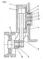
- a drive cylinder shown is formed according to FIG. 1 with a lateral flange 2 and a pin 3 attached to it in a recess in a vehicle side wall 4 and pivotably arranged with the aid of bearing shells 5 and held axially by a pin cover 6.
- a piston 7 with a piston rod 8 which is rotatably mounted on a rear part of an impeller shaft 9.
- the impeller shaft 9 itself is located in a support arm 10, which in turn is pivotally mounted in the vehicle side wall 4.
- an impeller 11 At the front on the impeller shaft 9 there is an impeller 11.
- This can be used via the cylinder 1 with the piston 7, depending on the hydraulic control, as a vibration damper, as a hydraulic spring element or as a blocking element for mechanical suspension.
- Corresponding hydraulic connecting lines 12, 13 are guided through the pin 3 and the flange 2 and are protected against the effects of dirt and foreign objects.
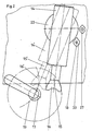
- a drive cylinder 14, between two positions 14, 14 ', can be pivoted back and forth. In this case it is used as a switchable support and locking cylinder for a roller. In position 14, the piston rod 15 is retracted into the cylinder with a support shell 16. The associated roller can swing freely past the cylinder 14 with its rear shaft journal 17.
- position 14 is clearly defined by bolt 18.
- the bolt 18 also determines the position of the position 14 ', in which, however, the cylinder remains pivotable about the small angular range so that it can follow the deflection path 19 of the shaft journal 17.
- the drive cylinder 14 is rotatably arranged with an intermediate part 20 in the vehicle side wall 4 via the two bearing shells 5.
- the flange plate 21 screwed from the inside ensures the axial fixation of the drive cylinder 14 in the side wall 4.
- the cylinder flange 22 is used in conjunction with a sealing element 23 in the side wall 4 to protect the bearing shells 5 from external contamination.
- This sealing element 23 also causes an increase in the frictional force for the pivoting movement, so that the drive cylinder 14 remains in a set position as long as no external forces act on it.
- the flange plate 21 contains on its outer circumference a toothed segment 24 which cooperates with a pinion 25.
- This pinion 25 is mounted with its shaft 26 in the side wall 4 and carries an actuating knob 27 on the outside of the vehicle wall 4.
- the drive cylinder between the two positions 14, 14 ' is in accordance with Fig. 2 pivoted back and forth. This pivoting movement is also indicated in Fig. 3 by the two contours 28,28 '.
- the pivoting movement is limited by the pin 18, see also FIG. 5, which is mounted in the vehicle side wall 4 and contains two contours 29, 30 on the inside, which are located in different planes.
- the contour 29 is, for example, a circular contour, which is in engagement with the milling 31 in the flange. Both together define the possible pivot angle of the drive cylinder 14, compare again the contours 28,28 '.
- the contour 30 is, for example, a semicircular contour, which can be arranged either in position 30 or in position 30 '. In position 30 it locks the cylinder 14 according to the contour 28 in the rest position 14 (FIG. 2) by engaging in a recess 32 of the flange plate 21. This position is in remaining self-locking, because movement of the drive cylinder is prevented by external forces in one direction through the circular contour 29 and in the opposite direction meets the outer radius of the contour 30, so that it is additionally rotated in the direction of locking.
- the flange plate 21 is released and can be rotated together with the drive cylinder 14 using the pinion 25 in the support position 28'.
- the drive cylinder is self-locking in its pivot bearing and, on the other hand, it is guided through the shaft journal 17 of the impeller shaft after it has been extended.
- the locking bolt 18 is also mounted in the vehicle side wall 4 in a self-locking manner, the self-locking being set by prestressed spring elements 34. Both the pin 18 and the pinion shaft 26 are protected against the ingress of dirt and foreign bodies by sealing elements 35, 36.
Landscapes
- Engineering & Computer Science (AREA)
- Chemical & Material Sciences (AREA)
- Combustion & Propulsion (AREA)
- Transportation (AREA)
- Mechanical Engineering (AREA)
- Vehicle Body Suspensions (AREA)
- Framework For Endless Conveyors (AREA)
Applications Claiming Priority (2)
| Application Number | Priority Date | Filing Date | Title |
|---|---|---|---|
| DE19873737928 DE3737928A1 (de) | 1987-11-07 | 1987-11-07 | Vorrichtung fuer laufwerksausbildungen von kettenfahrzeugen mit laufwerkszylindern |
| DE3737928 | 1987-11-07 |
Publications (3)
| Publication Number | Publication Date |
|---|---|
| EP0315764A2 true EP0315764A2 (fr) | 1989-05-17 |
| EP0315764A3 EP0315764A3 (en) | 1989-12-27 |
| EP0315764B1 EP0315764B1 (fr) | 1991-12-18 |
Family
ID=6340068
Family Applications (1)
| Application Number | Title | Priority Date | Filing Date |
|---|---|---|---|
| EP88115777A Expired - Lifetime EP0315764B1 (fr) | 1987-11-07 | 1988-09-24 | Disposition perfectionnée de trains de roulement suspendus hydrauliquement pour véhicules chenilles |
Country Status (2)
| Country | Link |
|---|---|
| EP (1) | EP0315764B1 (fr) |
| DE (2) | DE3737928A1 (fr) |
Cited By (3)
| Publication number | Priority date | Publication date | Assignee | Title |
|---|---|---|---|---|
| FR2649950A1 (fr) * | 1989-07-24 | 1991-01-25 | Leitner Spa | Vehicule a chenilles en particulier pour la preparation des pentes skiables |
| EP0525957A1 (fr) * | 1991-07-30 | 1993-02-03 | General Dynamics Land Systems, Inc. | Suspension pour une roue de véhicule à chenilles |
| EP2108533A1 (fr) * | 2008-04-08 | 2009-10-14 | Alois Johann Haringer | Véhicule à chenilles |
Families Citing this family (1)
| Publication number | Priority date | Publication date | Assignee | Title |
|---|---|---|---|---|
| DE4123778C2 (de) * | 1990-10-01 | 1996-03-14 | Krauss Maffei Ag | Gleiskettenfahrzeug |
Family Cites Families (4)
| Publication number | Priority date | Publication date | Assignee | Title |
|---|---|---|---|---|
| FR1401309A (fr) * | 1964-04-20 | 1965-06-04 | Creusot Forges Ateliers | Véhicule à chenilles à poulies de tension réglables longitudinalement et verticalement |
| US3614125A (en) * | 1970-03-31 | 1971-10-19 | Us Army | Unitized high-mobility suspension and drive system for track vehicles |
| DE3039366A1 (de) * | 1980-10-18 | 1982-05-19 | Dr.Ing.H.C. F. Porsche Ag, 7000 Stuttgart | Gleiskettenfahrzeug |
| DE3433262A1 (de) * | 1984-09-11 | 1986-03-20 | Krupp Mak Maschinenbau Gmbh, 2300 Kiel | Vorrichtung zur starren laufwerksausbildung |
-
1987
- 1987-11-07 DE DE19873737928 patent/DE3737928A1/de active Granted
-
1988
- 1988-09-24 EP EP88115777A patent/EP0315764B1/fr not_active Expired - Lifetime
- 1988-09-24 DE DE8888115777T patent/DE3867038D1/de not_active Expired - Fee Related
Cited By (4)
| Publication number | Priority date | Publication date | Assignee | Title |
|---|---|---|---|---|
| FR2649950A1 (fr) * | 1989-07-24 | 1991-01-25 | Leitner Spa | Vehicule a chenilles en particulier pour la preparation des pentes skiables |
| EP0525957A1 (fr) * | 1991-07-30 | 1993-02-03 | General Dynamics Land Systems, Inc. | Suspension pour une roue de véhicule à chenilles |
| EP2108533A1 (fr) * | 2008-04-08 | 2009-10-14 | Alois Johann Haringer | Véhicule à chenilles |
| WO2009124714A1 (fr) * | 2008-04-08 | 2009-10-15 | Alois Johann Haringer | Véhicule à chenilles |
Also Published As
| Publication number | Publication date |
|---|---|
| DE3737928C2 (fr) | 1991-06-13 |
| EP0315764A3 (en) | 1989-12-27 |
| DE3737928A1 (de) | 1989-05-24 |
| EP0315764B1 (fr) | 1991-12-18 |
| DE3867038D1 (de) | 1992-01-30 |
Similar Documents
| Publication | Publication Date | Title |
|---|---|---|
| DE68914554T2 (de) | Mehrachsiger mechanischer manipulator mit überlastschutz. | |
| EP2688710B1 (fr) | Dispositif de meuleuse a montage pivotant d'une unite de broche porte-meule et procede permettant de faire pivoter une unite de broche porte-meule sur une meuleuse | |
| DE3151621C2 (de) | Trittstufe für Fahrzeuge, insbesondere Schienenfahrzeuge | |
| DE1755888C3 (de) | Radaufhängung für Kraftfahrzeuge | |
| DE10158022A1 (de) | Kugelgelenk mit einem System zur Beschränkung einer Winkelbewegung | |
| CH644555A5 (en) | Device for controlling the swivelling movement of a wheel set of a rail vehicle in a bend | |
| DE3147938C2 (de) | Einstellvorrichtung für die optische Achse eines Scheinwerfers für Kraftfahrzeuge | |
| DE3022939C2 (de) | Vorrichtung zum Korrigieren der Ausrichtung eines Kraftfahrzeugscheinwerfers mit einem Trägheitspendel | |
| DE2738816A1 (de) | Anbaudrehpflug | |
| DE19810480A1 (de) | Scheinwerfer für ein Fahrzeug | |
| EP0698524B1 (fr) | Accoudoir réglable pour véhicules automobiles | |
| EP0315764B1 (fr) | Disposition perfectionnée de trains de roulement suspendus hydrauliquement pour véhicules chenilles | |
| DE29914042U1 (de) | Türscharnier für Kraftfahrzeugtüren mit integriertem Feststeller | |
| DE3839322A1 (de) | Fahrzeug-aussenspiegel | |
| DE69007179T2 (de) | Mechanismen zur Längsverstellung von Fahrzeugsitzen. | |
| EP0240877B1 (fr) | Recouvrement télescopique | |
| EP0514672B1 (fr) | Dispositif pour amortir respectivement commander la mise en portefeuille entre les véhicules partiels d'un véhicule articulé | |
| EP0227686B1 (fr) | Ensemble de direction, surtout pour les vehicules a moteur a voie etroite | |
| DE2432856A1 (de) | Diamant-abrichtvorrichtung | |
| DE3709928A1 (de) | Einzelradaufhaengung | |
| DE1219812B (de) | Radaufhaengung fuer Kraftfahrzeuge | |
| EP0006491B1 (fr) | Dispositif pour supporter une installation d'armes sur un véhicule de combat | |
| DE3539335C2 (fr) | ||
| EP0122325A2 (fr) | Dispositif de réouverture pour portes de véhicules actionnées par des colonnes tournantes, ou coulissantes | |
| DE3024910A1 (de) | Bearbeitungsgeraet zum formen von schleifscheiben |
Legal Events
| Date | Code | Title | Description |
|---|---|---|---|
| PUAI | Public reference made under article 153(3) epc to a published international application that has entered the european phase |
Free format text: ORIGINAL CODE: 0009012 |
|
| AK | Designated contracting states |
Kind code of ref document: A2 Designated state(s): DE FR GB |
|
| PUAL | Search report despatched |
Free format text: ORIGINAL CODE: 0009013 |
|
| AK | Designated contracting states |
Kind code of ref document: A3 Designated state(s): DE FR GB |
|
| 17P | Request for examination filed |
Effective date: 19900110 |
|
| 17Q | First examination report despatched |
Effective date: 19910301 |
|
| RAP1 | Party data changed (applicant data changed or rights of an application transferred) |
Owner name: MAK SYSTEM GESELLSCHAFT MBH |
|
| GRAA | (expected) grant |
Free format text: ORIGINAL CODE: 0009210 |
|
| AK | Designated contracting states |
Kind code of ref document: B1 Designated state(s): DE FR GB |
|
| REF | Corresponds to: |
Ref document number: 3867038 Country of ref document: DE Date of ref document: 19920130 |
|
| GBT | Gb: translation of ep patent filed (gb section 77(6)(a)/1977) | ||
| ET | Fr: translation filed | ||
| PLBE | No opposition filed within time limit |
Free format text: ORIGINAL CODE: 0009261 |
|
| STAA | Information on the status of an ep patent application or granted ep patent |
Free format text: STATUS: NO OPPOSITION FILED WITHIN TIME LIMIT |
|
| 26N | No opposition filed | ||
| PGFP | Annual fee paid to national office [announced via postgrant information from national office to epo] |
Ref country code: GB Payment date: 20000814 Year of fee payment: 13 |
|
| PG25 | Lapsed in a contracting state [announced via postgrant information from national office to epo] |
Ref country code: GB Free format text: LAPSE BECAUSE OF NON-PAYMENT OF DUE FEES Effective date: 20010924 |
|
| REG | Reference to a national code |
Ref country code: FR Ref legal event code: CD |
|
| REG | Reference to a national code |
Ref country code: GB Ref legal event code: IF02 |
|
| GBPC | Gb: european patent ceased through non-payment of renewal fee |
Effective date: 20010924 |
|
| PGFP | Annual fee paid to national office [announced via postgrant information from national office to epo] |
Ref country code: DE Payment date: 20040907 Year of fee payment: 17 |
|
| PGFP | Annual fee paid to national office [announced via postgrant information from national office to epo] |
Ref country code: FR Payment date: 20040910 Year of fee payment: 17 |
|
| PG25 | Lapsed in a contracting state [announced via postgrant information from national office to epo] |
Ref country code: DE Free format text: LAPSE BECAUSE OF NON-PAYMENT OF DUE FEES Effective date: 20060401 |
|
| PG25 | Lapsed in a contracting state [announced via postgrant information from national office to epo] |
Ref country code: FR Free format text: LAPSE BECAUSE OF NON-PAYMENT OF DUE FEES Effective date: 20060531 |
|
| REG | Reference to a national code |
Ref country code: FR Ref legal event code: ST Effective date: 20060531 |