EP0315770A2 - Outil à moulage par compression pour pièces de moulage en matière plastique - Google Patents
Outil à moulage par compression pour pièces de moulage en matière plastique Download PDFInfo
- Publication number
- EP0315770A2 EP0315770A2 EP88116276A EP88116276A EP0315770A2 EP 0315770 A2 EP0315770 A2 EP 0315770A2 EP 88116276 A EP88116276 A EP 88116276A EP 88116276 A EP88116276 A EP 88116276A EP 0315770 A2 EP0315770 A2 EP 0315770A2
- Authority
- EP
- European Patent Office
- Prior art keywords
- tool
- parts
- tool according
- press
- press tool
- Prior art date
- Legal status (The legal status is an assumption and is not a legal conclusion. Google has not performed a legal analysis and makes no representation as to the accuracy of the status listed.)
- Withdrawn
Links
Images



Classifications
-
- B—PERFORMING OPERATIONS; TRANSPORTING
- B29—WORKING OF PLASTICS; WORKING OF SUBSTANCES IN A PLASTIC STATE IN GENERAL
- B29C—SHAPING OR JOINING OF PLASTICS; SHAPING OF MATERIAL IN A PLASTIC STATE, NOT OTHERWISE PROVIDED FOR; AFTER-TREATMENT OF THE SHAPED PRODUCTS, e.g. REPAIRING
- B29C33/00—Moulds or cores; Details thereof or accessories therefor
- B29C33/30—Mounting, exchanging or centering
- B29C33/305—Mounting of moulds or mould support plates
-
- B—PERFORMING OPERATIONS; TRANSPORTING
- B29—WORKING OF PLASTICS; WORKING OF SUBSTANCES IN A PLASTIC STATE IN GENERAL
- B29C—SHAPING OR JOINING OF PLASTICS; SHAPING OF MATERIAL IN A PLASTIC STATE, NOT OTHERWISE PROVIDED FOR; AFTER-TREATMENT OF THE SHAPED PRODUCTS, e.g. REPAIRING
- B29C43/00—Compression moulding, i.e. applying external pressure to flow the moulding material; Apparatus therefor
- B29C43/32—Component parts, details or accessories; Auxiliary operations
- B29C43/36—Moulds for making articles of definite length, i.e. discrete articles
-
- B—PERFORMING OPERATIONS; TRANSPORTING
- B30—PRESSES
- B30B—PRESSES IN GENERAL
- B30B15/00—Details of, or accessories for, presses; Auxiliary measures in connection with pressing
- B30B15/02—Dies; Inserts therefor; Mounting thereof; Moulds
Definitions
- the invention relates to a pressing tool for the production of molded parts from plastics, in particular from fiber-reinforced plastics, consisting of a lower part which can be firmly connected to the frame of the press and an upper part which is movably guided and can be connected to a drive of the frame.
- Molded parts for example made of fiber-reinforced plastics, such as leaf springs, are usually produced in presses using interchangeable pressing tools.
- a correspondingly designed, complete tool must be provided for molded parts of different shapes or dimensions.
- the molded parts will be provided with radii on the flanks.
- plunge edge tools a radius can be created on one side through the cavity of the die directly during the pressing process. This usually happens on the underside of the molded part, the pull side. If you also wanted to shape the upper radii on the pressure side with the tool, two sharp cutting edges would result on the patrix. Given the required dimensions, these can only be produced with great effort and would limit the service life of the tool to a minimum. The necessary radii are therefore milled in a subsequent machining step. Disadvantages here are the disruption of the molded part structure due to the cutting of the fiber strands during milling and the additional manufacturing outlay.
- the closed and rigid structure of such a tool makes it difficult to handle with regard to loading with raw material and the removal of the molded parts.
- the material to be preheated must be outside the mold.
- the present invention is therefore based on the object of developing a pressing tool which, in the production of molded plastic parts, reduces both the tooling and the process engineering outlay in comparison with the conventional manufacturing technology.
- the solution to the problem consists in a pressing tool of the type described in which, according to the present invention, the upper and The lower part of the tool, together with drive elements for the closing of parts delimiting the mold cavity, form a master unit and the predetermined parts are held interchangeably in the master unit and the movable parts can be releasably connected to the drive elements.
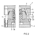
- the pressing tool consists essentially of a trunk unit with the upper part 1 and the lower part 2 and from the parts forming the mold cavity 3, which are interchangeable (FIGS. 1 and 2).
- the upper part 1 consists of an upper clamping plate 4 with a locking cone plate 5, which is provided with pressure strips 6 in the conical part.
- Guide columns 7 are provided in the edge region of the upper part.
- the lower part 2 of the tool has a lower clamping plate 8, which receives an intermediate plate 10 by means of spacer strips 9.
- corresponding guide sleeves 11 are provided with the guide columns 7, so that the upper and lower part can be centered and moved parallel to one another.
- the upper part is driven in the press frame (not shown in the drawing), in which the two tool parts 1 and 2 are inserted, in a known manner mechanically, for example by means of an eccentric, or hydraulically by means of a working cylinder.
- the press tool can be operated without a press.
- the piston rods 13 at its free end receive the upper part 1 for guiding and driving the same. This allows the tool to be opened or closed and the locking force to be applied.
- the shaping parts are an upper die 14 held in the upper part 1, a lower die 15 held in the lower part 2 and two side walls 16. All parts can be moved towards one another within the tool to form the mold cavity 3 and are provided with the shaping profile on their surfaces .
- the upper die 14 exerting the pressing force is axially displaceably guided on guide pins 17 by means of ball bearings 18 and releasably held on piston rods 19 (FIG. 4) by working cylinders 20 by means of a screw connection.
- Guide bolts and working cylinders are clamped with collar-like extensions 21, 22 in bores 23 between the upper clamping plate 4 and the locking cone plate 5.
- the lower die 15 is slidably held on a step 24 in an elongated opening 25 of the intermediate plate 10 in the longitudinal extent of the tool and is fastened by means of pins 27 which engage in lateral bores 26 of the die and are guided in the spacer strips 9.
- This embodiment allows the die to be replaced quickly and easily by extending laterally from the lower part.
- the arrangement of the form stamps can also be reversed with respect to the axial displaceability and the stationary holder, so that the lower form stamp is axially displaceable analogously to the above explanation, the lower part 2 is equipped with the corresponding guides and working cylinders and the upper form stamp can be laterally displaced and locked .
- the two side walls 16 are arranged symmetrically to the tool axis 28 and can be moved on the intermediate plate 10 in guide rails 29 by means of sliding elements 30 to the axis.
- guide elements 31 fastened therein get into bores 32 of the guide strips and take the sliding elements with the side cheeks into the closed position of the form in which, as can be seen in FIG. 2, they pass through the inner surface 33 of the locking cone plate 5 and the pressure bars 6 are positioned exactly.
- the sliding elements with the side cheeks are pulled back into the open position.
- the sliding elements 30 can also be moved together with the side cheeks 16 according to the embodiment in FIG. 3 by working cylinders 34.
- a groove 35 corresponding to the intended molded part contour is machined into the side cheeks 16, through which rounded edges are formed on the molded part 36 during the pressing process.
- a mold core 37 is arranged between the upper die 14 and the lower die 15, so that a double mold cavity is formed. It is understood that in this case the upper and lower dies have the same surface profile.
- the shaping parts 14, 15, 16 heatable in order to heat the material to be shaped.
- electrical heating elements 38 can be used in bores 39 of the parts. It is expedient to indirectly temper the side walls 16 via the sliding elements 30. In the case of ceramic materials for the parts, the heating can also be done dielectrically by means of high-frequency electromagnetic energy transmission.
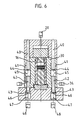
- FIGS. 5 and 6 show an embodiment of the pressing tool in which the upper part 1 and the side walls 16, which are brought into the closed position by means of a working cylinder, are locked by an axially parallel, three-part locking system.
- the first part consists of rods 40 which are fastened symmetrically to the tool axis 28 in the upper part.
- the sliding elements 30 have bores 41 which are arranged coaxially to the rods in the closed position of the sliding elements. Further rods 42 are slidably guided in these bores, which in turn are assigned bores 43 in the third part, the lower part 2.
- the non-positive connection of the three-part system for locking the tool parts in the closed position can be produced in that on the one hand the free end of the rods 40, 42 and on the other hand the rods 42 and the bores 43 with locking elements 44, 45 and which can be brought into engagement with axial movement of the rods 46, 47 are provided.
- Such elements are available in specialist shops and can be, for example, by an annular groove at the end of the rod and a spring-loaded in the associated hole Ball bearings are formed.
- the locking parts 45 assigned to the rods 40 are firmly connected to the rods 42, while the parts 47 assigned to the rods 42 are held in the bores 43 with axial play.
- the locking parts 47 held in the lower part 2 are connected to pneumatic or hydraulic working cylinders 48.
- the locking of the tool parts described above begins with the rods 40 in the bores 41 of the sliding elements 30 previously brought into the closed position and thereby engaging with the locking parts 45 while closing the upper part 1, so that the rods 42 in the further course of movement the holes 43 are pushed and pressed further into the locking parts 47.
- the lock is tensioned and is therefore free of play.
- the pressing tool is prepared for the pressing process by the die 14. The locking is released after the pressing process by opening the upper part in the reverse manner.
- the tool can be opened on all sides, so that the introduction of the material to be molded and the removal of the molded part are made very easy. This also favors the use of handling mechanisms.
- the pressing tool according to the invention has decisive advantages for the production process.
- the new tool includes a multitude of options for designing the production process in a cost-effective, flexible and rational manner and reducing the tooling effort to a minimum. Further advantages of the tool construction according to the invention are shown below: -
- molded parts for example from reaction resin prepregs or thermoplastic prepregs, of different shapes and sizes, it is necessary to procure just one master unit. The design and dimensions of the master unit are selected according to the largest molded part to be produced.
- any shape geometry is then possible due to the design freedom of the shaping exchange parts.
- All guide elements and drive elements are part of the master unit.
- the molding costs are significantly reduced by the geometrically simple, shaping replacement parts, namely the upper and lower dies and two side walls.
- the replacement parts are protected and supported by the parent unit surrounding them and therefore do not have to absorb all of the forces that occur. This makes it possible to choose different materials, such as steel, aluminum, brass, epoxy resin, ceramics, glass and plastics.
- Radii on both the top and bottom of the molded part are formed by a groove corresponding to the molded part contour in the side cheeks during manufacture in the tool. This avoids the cutting of fibers that occurred during the subsequent milling that was previously necessary.
- One of the two form punches can be moved in the direction of the tool axis within the master unit by a working cylinder. This allows the press cycle to run independently of the press control. The compression work and the pressure can be applied independently of external devices. This makes it possible to dispense with the use of complex presses and instead to use cheaper tool carriers.
- the lower die can be pushed out of the side of the trunk unit. This makes it possible to exchange the stamp between the press cycles in a mechanized work step, for example against a stamp prepared outside the master unit with new molding material.
Landscapes
- Engineering & Computer Science (AREA)
- Mechanical Engineering (AREA)
- Moulds For Moulding Plastics Or The Like (AREA)
- Casting Or Compression Moulding Of Plastics Or The Like (AREA)
Applications Claiming Priority (2)
| Application Number | Priority Date | Filing Date | Title |
|---|---|---|---|
| DE19873733873 DE3733873A1 (de) | 1987-10-07 | 1987-10-07 | Presswerkzeug fuer kunststofformteile |
| DE3733873 | 1987-10-07 |
Publications (2)
| Publication Number | Publication Date |
|---|---|
| EP0315770A2 true EP0315770A2 (fr) | 1989-05-17 |
| EP0315770A3 EP0315770A3 (fr) | 1991-03-06 |
Family
ID=6337792
Family Applications (1)
| Application Number | Title | Priority Date | Filing Date |
|---|---|---|---|
| EP19880116276 Withdrawn EP0315770A3 (fr) | 1987-10-07 | 1988-10-01 | Outil à moulage par compression pour pièces de moulage en matière plastique |
Country Status (3)
| Country | Link |
|---|---|
| US (1) | US4971543A (fr) |
| EP (1) | EP0315770A3 (fr) |
| DE (1) | DE3733873A1 (fr) |
Cited By (2)
| Publication number | Priority date | Publication date | Assignee | Title |
|---|---|---|---|---|
| WO2009106341A3 (fr) * | 2008-02-27 | 2009-11-26 | Airbus Operations Gmbh | Procédé de production d'une préforme profilée et d'un composant profilé en matière plastique renforcée par des fibres, installation de pultrusion et dispositif de pressage pour mettre en oeuvre ce procédé |
| CN102848494A (zh) * | 2012-09-08 | 2013-01-02 | 谢力志 | 双向驱动智能开合模机 |
Families Citing this family (9)
| Publication number | Priority date | Publication date | Assignee | Title |
|---|---|---|---|---|
| JP2871795B2 (ja) * | 1990-03-13 | 1999-03-17 | 富士重工業株式会社 | 複合材部品成形型 |
| JPH0735575Y2 (ja) * | 1992-10-19 | 1995-08-16 | 義雄 清水 | 握りずし成形型 |
| GB2342063A (en) * | 1998-09-30 | 2000-04-05 | Rover Group | A press tool and a wear block therefor |
| US6416312B1 (en) * | 1999-06-02 | 2002-07-09 | Alcoa Closure Systems International | Cam mechanism with side action for compression molding process |
| RU2176590C1 (ru) * | 2000-03-27 | 2001-12-10 | Общество с ограниченной ответственностью "Торговый дом "Абразивные заводы Урала" | Пресс-форма для формования заготовок абразивных кругов на вулканитовой связке |
| CN2820502Y (zh) * | 2005-06-16 | 2006-09-27 | 鸿富锦精密工业(深圳)有限公司 | 热成型模具 |
| CN101190554A (zh) * | 2006-12-01 | 2008-06-04 | 鸿富锦精密工业(深圳)有限公司 | 模具装置 |
| DE102017106521A1 (de) | 2017-03-27 | 2018-09-27 | Schmidt & Heinzmann Gmbh & Co. Kg | Formwerkzeug |
| EP4192663B1 (fr) * | 2020-08-05 | 2025-10-15 | Sacmi Cooperativa Meccanici Imola Societa' Cooperativa | Appareil et procédé de moulage |
Family Cites Families (18)
| Publication number | Priority date | Publication date | Assignee | Title |
|---|---|---|---|---|
| US1623022A (en) * | 1926-02-18 | 1927-03-29 | Louis W Hottel | Molding-press apparatus |
| US2703435A (en) * | 1949-09-15 | 1955-03-08 | Dentists Supply Co | Apparatus for molding artificial teeth |
| US2913766A (en) * | 1957-02-11 | 1959-11-24 | Haller John | Briquetting die set |
| US3378885A (en) * | 1959-11-27 | 1968-04-23 | Dart Mfg Company | Apparatus for forming thin wall cellular plastic containers |
| US3373460A (en) * | 1965-09-13 | 1968-03-19 | Michael Ladney Jr. | Molding apparatus |
| US3524220A (en) * | 1967-11-15 | 1970-08-18 | Western Electric Co | Die set for compacting powder |
| FR2061839A5 (fr) * | 1969-05-29 | 1971-06-25 | Crouzet & Cie | |
| GB1352341A (en) * | 1970-06-26 | 1974-05-08 | Gkn Sankey Ltd | Manufacture of articles |
| GB1422705A (en) * | 1972-02-01 | 1976-01-28 | Tupperware Australia Pty Ltd | Moulding apparatus |
| DD113183A1 (fr) * | 1974-07-29 | 1975-05-20 | ||
| ZA755683B (en) * | 1975-09-05 | 1977-04-27 | Morrison Pumps Sa | Presses |
| US4184835A (en) * | 1978-09-28 | 1980-01-22 | General Electric Company | Mold apparatus |
| DE3006227C2 (de) * | 1979-02-22 | 1985-10-24 | Motor Wheel Corp., Lansing, Mich. | Formgepreßtes Kunststoffrad |
| DE2935077C2 (de) * | 1979-08-30 | 1986-04-10 | Laeis GmbH, 5500 Trier | Presse für keramische Formlinge |
| US4306851A (en) * | 1980-11-26 | 1981-12-22 | General Motors Corporation | Cam acting core lock and straightener |
| US4477406A (en) * | 1981-09-22 | 1984-10-16 | Deere & Company | Method for molding elongated workpieces |
| US4502660A (en) * | 1983-11-21 | 1985-03-05 | Luther Leroy D | Mold including side walls with locking projections |
| US4620958A (en) * | 1984-09-28 | 1986-11-04 | At&T Technologies, Inc. | Methods of and apparatus for molding articles through a balanced, removable runner system |
-
1987
- 1987-10-07 DE DE19873733873 patent/DE3733873A1/de not_active Withdrawn
-
1988
- 1988-10-01 EP EP19880116276 patent/EP0315770A3/fr not_active Withdrawn
- 1988-10-05 US US07/253,500 patent/US4971543A/en not_active Expired - Fee Related
Cited By (3)
| Publication number | Priority date | Publication date | Assignee | Title |
|---|---|---|---|---|
| WO2009106341A3 (fr) * | 2008-02-27 | 2009-11-26 | Airbus Operations Gmbh | Procédé de production d'une préforme profilée et d'un composant profilé en matière plastique renforcée par des fibres, installation de pultrusion et dispositif de pressage pour mettre en oeuvre ce procédé |
| US8815036B2 (en) | 2008-02-27 | 2014-08-26 | Airbus Operations Gmbh | Method for manufacturing a profiled preform |
| CN102848494A (zh) * | 2012-09-08 | 2013-01-02 | 谢力志 | 双向驱动智能开合模机 |
Also Published As
| Publication number | Publication date |
|---|---|
| US4971543A (en) | 1990-11-20 |
| EP0315770A3 (fr) | 1991-03-06 |
| DE3733873A1 (de) | 1989-04-27 |
Similar Documents
| Publication | Publication Date | Title |
|---|---|---|
| EP1673208B1 (fr) | Machine de moulage par injection horizontale pourvue d'un dispositif tournant | |
| EP2103423B1 (fr) | Presse à poudre destinée à la fabrication d'une pièce pressée en poudre de métal | |
| EP0418779B1 (fr) | Méthode pour manufacture de pièces d'oeuvre par découpage, en particulier dans un outil à contre découpage à précision | |
| EP0315770A2 (fr) | Outil à moulage par compression pour pièces de moulage en matière plastique | |
| EP0576837B1 (fr) | Machine à mouler par injection avec moule à étages | |
| EP0074473A1 (fr) | Procédé et dispositif pour la fabrication de pièces de forme ou des objets en matière plastique | |
| WO2013072459A2 (fr) | Dispositif de verrouillage de longerons d'une machine de traitement de matière plastique | |
| EP2134528B1 (fr) | Moule avec cadre, à structure modulaire | |
| EP2543490B1 (fr) | Unité de fermeture pour une machine de moulage par injection | |
| DE102020108596A1 (de) | Verfahren und Vorrichtung zur Herstellung von mehrkomponentigen Kunststoffformteilen | |
| DE4311154A1 (de) | Verfahren und Einrichtung zur Finishbearbeitung von tuschierten Werkzeugen | |
| EP1858682A1 (fr) | Dispositif pour recevoir un moule | |
| EP0421088A2 (fr) | Dispositif de fermeture de moule pour une machine à mouler par injection | |
| DE10101837B4 (de) | Auswerfvorrichtung für eine Formmaschine | |
| DE10308303B4 (de) | Spritzgießeinrichtung mit einer Verriegelungseinrichtung | |
| AT526987B1 (de) | Anordnung aus einer Formaufspannplatte für eine Formgebungsmaschine und zumindest einer Verriegelungsvorrichtung | |
| DD259957A3 (de) | Einrichtung zum vertikalen wechseln und spannen von formwerkzeugen | |
| AT526511B1 (de) | Schließeinheit sowie eine Formgebungsmaschine mit einer solchen Schließeinheit | |
| AT528004B1 (de) | Maschinenelement zum Aufspannen einer Form | |
| DE4329401C2 (de) | Anlage für die Durchführung eines Arbeitsverfahrens zum Einbauen und Ausbauen eines aus Unterform und Oberform bestehenden, mit komplementären Wellflächen versehenen Formensatzes, bei einer Plattenpresse für das Pressen von Preßgutmatten im Zuge der Herstellung von Faserzement-Wellplatten | |
| EP4284623B1 (fr) | Moule pour former de manière flexible une surface de moule | |
| EP3871855B1 (fr) | Système de transfert avec un dispositif d'injection intégré sur une table de livraison | |
| EP0289857B1 (fr) | Unité de fermeture pour machines à mouler par injection | |
| DE1729154A1 (de) | Formschliess- und -oeffnungsvorrichtung fuer Spritzgiessmaschinen | |
| DE102025139359A1 (de) | Schließeinheit für eine Formgebungsmaschine |
Legal Events
| Date | Code | Title | Description |
|---|---|---|---|
| PUAI | Public reference made under article 153(3) epc to a published international application that has entered the european phase |
Free format text: ORIGINAL CODE: 0009012 |
|
| AK | Designated contracting states |
Kind code of ref document: A2 Designated state(s): AT BE CH DE ES FR GB IT LI NL SE |
|
| PUAL | Search report despatched |
Free format text: ORIGINAL CODE: 0009013 |
|
| 17P | Request for examination filed |
Effective date: 19901227 |
|
| AK | Designated contracting states |
Kind code of ref document: A3 Designated state(s): AT BE CH DE ES FR GB IT LI NL SE |
|
| 17Q | First examination report despatched |
Effective date: 19920323 |
|
| STAA | Information on the status of an ep patent application or granted ep patent |
Free format text: STATUS: THE APPLICATION HAS BEEN WITHDRAWN |
|
| 18W | Application withdrawn |
Withdrawal date: 19930205 |