EP0315936A1 - Klotzteil zum Festsetzen von Glasscheiben od. dgl. - Google Patents
Klotzteil zum Festsetzen von Glasscheiben od. dgl. Download PDFInfo
- Publication number
- EP0315936A1 EP0315936A1 EP88118539A EP88118539A EP0315936A1 EP 0315936 A1 EP0315936 A1 EP 0315936A1 EP 88118539 A EP88118539 A EP 88118539A EP 88118539 A EP88118539 A EP 88118539A EP 0315936 A1 EP0315936 A1 EP 0315936A1
- Authority
- EP
- European Patent Office
- Prior art keywords
- block part
- longitudinal slot
- support
- support plate
- side projection
- Prior art date
- Legal status (The legal status is an assumption and is not a legal conclusion. Google has not performed a legal analysis and makes no representation as to the accuracy of the status listed.)
- Granted
Links
- 239000011521 glass Substances 0.000 title claims abstract description 16
- 239000000463 material Substances 0.000 abstract description 11
- 238000007789 sealing Methods 0.000 description 4
- XLYOFNOQVPJJNP-UHFFFAOYSA-N water Substances O XLYOFNOQVPJJNP-UHFFFAOYSA-N 0.000 description 4
- 238000009825 accumulation Methods 0.000 description 1
- 238000005452 bending Methods 0.000 description 1
- 230000006835 compression Effects 0.000 description 1
- 238000007906 compression Methods 0.000 description 1
- 230000005494 condensation Effects 0.000 description 1
- 238000009833 condensation Methods 0.000 description 1
- 238000005457 optimization Methods 0.000 description 1
- 239000000725 suspension Substances 0.000 description 1
Images
Classifications
-
- E—FIXED CONSTRUCTIONS
- E06—DOORS, WINDOWS, SHUTTERS, OR ROLLER BLINDS IN GENERAL; LADDERS
- E06B—FIXED OR MOVABLE CLOSURES FOR OPENINGS IN BUILDINGS, VEHICLES, FENCES OR LIKE ENCLOSURES IN GENERAL, e.g. DOORS, WINDOWS, BLINDS, GATES
- E06B3/00—Window sashes, door leaves, or like elements for closing wall or like openings; Layout of fixed or moving closures, e.g. windows in wall or like openings; Features of rigidly-mounted outer frames relating to the mounting of wing frames
- E06B3/54—Fixing of glass panes or like plates
- E06B3/5409—Means for locally spacing the pane from the surrounding frame
Definitions
- the invention relates to a block part for fixing glass panes or the like in the grooves of door or window frames, with a support plate which has, in particular, longitudinally arranged support webs on the underside of the plate and, in particular, side projections located in the plane of the plate, and is provided with longitudinal slots which allow the projections to deflect.
- Such a block part is already known (DE-GM 87 05 528).
- its side walls lie closely adjacent to the groove walls of the frame profile, so that the block part as a whole is comparatively wide and a correspondingly large amount of material results.
- the invention has for its object to improve a block part of the type mentioned in such a way that the material requirement for the block part is reduced without foregoing its clamping in a frame groove by deflection of the projections.
- This object is achieved in that a single closed support plate longitudinal slot is closely adjacent to at least one side projection.
- the special arrangement of the longitudinal slot in relation to the side projection is important for the invention.
- the arrangement of the longitudinal slot which is closely adjacent to the side projection, enables the side projection to be compressed, as a result of which the clamping force required to fix the block part in a frame groove is generated.
- the suspension effect is limited to the range of motion of the side projection, without further areas of the support plate having to be used, which are consequently immobile and serve a correspondingly motion-free support of the glass pane when z. B. result from changes in cross section.
- the length of the longitudinal slot exceeds the extent of the side protrusion in the longitudinal direction of the plate, as a result of which the larger spring travel of the side protrusion that may be required is achieved.
- the width of the longitudinal slot corresponds to the maximum spring travel of the side projection. This dimensioning of the longitudinal slot thus limits the spring travel of the side protrusion, so that undesired overstressing of the material is avoided, but on the other hand the desired maximum clamping effect of the side protrusion can be guaranteed for a given length of the longitudinal slit.
- the side projection and the associated longitudinal slot are arranged symmetrically to one another transversely to the longitudinal direction of the plate.
- the longitudinal slot is at most about twice as long as the side projection protrudes laterally over the support plate. This results in an optimization between the required clamping force of the side projection on the one hand and the desired material saving, which results from the fact that the block part rests only with its comparatively widely projecting side projection on the side wall of the frame groove.
- the longitudinal slot of the support plate directly adjoins that portion of the block that is common to the support plate and the adjacent support web. In this way, the deformation of the block part remains correspondingly limited, that is to say without stressing further areas of the support plate when the side projection is deflected.
- the block part is designed so that the longitudinal slot of the support plate includes the block portion that is common to the support plate and the support web adjacent to the side projection, that the longitudinal slot is widened in the direction of the foot of the support web, and that the side projection is attached to the foot of the support web.
- the side projections are therefore not located in the plane of the plate, but rather below or at the foot of the support web.
- the longitudinal slot is pulled down from the plate level into the vicinity of the foot of the support web or into the vicinity of the side protrusion and thus forms a correspondingly large material recess in the support web, which allows the side protrusion to deflect widely without the support web itself compressing to a considerable extent got to.
- the deflection is therefore limited to that area of the support web which is arranged in the longitudinal area of the longitudinal slot.
- Such a configuration of the block part is particularly advantageous if the support webs are high.
- the side projection is arranged at the end of the support web remote from the plate and has a thickness that is high for the undercut.
- the arrangement of the side protrusion or all side protrusions of the block part at the end of the associated support web remote from the plate enables the side protrusions to be used not only for clamping parallel to the support plate in grooves in door or window frames, but also to undercut undercuts in door or frame grooves. Such reaching under provides additional protection of the block part against unintentional falling out of the groove and also makes it possible for the block part to be in the groove to move in the longitudinal direction without the risk of having to accept a change in position perpendicular to it.
- a frame profile 10 which carries an insulating glass pane 11, which is supported vertically via a block part 12 on a profile wall or a groove base 13.
- a profile strip 14 on one side of the insulating glass pane 11 and a glass retaining strip 15 on the other side of the insulating glass pane 11 serve to hold the glass pane 11.
- the glass holding strip 15 is snapped into the profile wall 13 of the frame profile 10 with a connecting rib 16.
- the lateral support of the insulating glass pane 11 takes place via elastic sealing strips 17 which are fastened to the profiled strip 14 and the glass retaining strip 15 by means of connecting ribs 18 by latching in corresponding connecting grooves.
- condensation can occur in the space between the insulating glass pane 11 and the frame profile 10 below the sealing strips 17 or accumulation of leakage water which occurs as a result of damaged or improperly fitted sealing strips 17.
- the groove 21 is formed by two support webs 22 which are arranged at a distance from one another on the underside 24 of a support plate 23 of the block part 12. Their spacing from one another is selected such that they lie approximately in one plane with the individual panes of the insulating glass pane 11, so that the regions of the support plate 23 located between the support webs 22 are not significantly loaded, but rather the main load is removed directly via the support webs 22.
- the block part 12 rests with its support webs 22 on the groove base 13 and is supported with side projections 25 on the groove side walls 26 of the frame profile. The support is carried out so that the block part 12 clamps.
- a total of three side projections 25 are provided, one on one side wall 27 in the middle of the block part 12 and two near the ends of the block part 12 on the other side wall 28 Ensure effort on side protrusions and thus on material for these side protrusions 25.
- the side projections 25 ensure the side projections 25, that the material expenditure for the block part 12 is kept correspondingly small in accordance with the distances a of FIG. 2 between the side walls 26 of the frame 10 and the side walls 27, 28 of the block part 12.
- the side projections 25 are arranged in the plate plane of the support plate 23, that is, they do not rest on the groove base 13 or come near it.
- the side projections 25 can also be arranged below the plate level or support plate 23.
- Longitudinal slots 29 are provided to allow the side protrusions 25 to deflect. These longitudinal slots 29 are closely adjacent to these side projections 25 and, in the case shown, are located directly after that block portion 30 which is common to a support web 22 and the support plate 23.
- the length 1 of the longitudinal slot 29 exceeds the extent of the side projection 25 in the longitudinal direction of the plate, that is, in the directions of the arrow 31.
- the longitudinal slot 29 with the associated side projection 25 is arranged symmetrically transversely to the longitudinal direction of the plate, that is to say symmetrically in the directions of the arrow 33 still to point out that the longitudinal slot 29 is at most twice as long as the side projection 25 protrudes laterally over the support plate 23.
- the block part of FIGS. 4 to 4b consists of a support plate 23 with three support webs 22 projecting in the same direction.
- the two outer support webs each have a side projection 25 at one end of the block part, which is arranged on the foot 35 of a support web 22.
- the deflection of the side projection 25 is made possible by a longitudinal slot 29, which comprises the block section 30 which is common to the support plate 23 and the associated support web 22 and extends in the direction of the foot 35.
- 4a shows that the foot 35 is provided with a recess 37 over the length of the longitudinal slot 29 in order to further increase the deflectability of the side projection 25 or the foot region carrying the latter.
- this recess 37, as well as the considerable height or transverse extension of the longitudinal slot 29, contribute to material savings.
- the block part 12 of FIG. 5 is assembled with a frame profile 10 which is only partially shown.
- the groove 21 has undercuts 38 on both sides, in which the side projections 25 of the block part 12 engage.
- the undercut 38 located on the profile strip 14 is formed by a projection 39 which is at a distance h from the base of the groove 13, as is the projection 40 on the opposite wall 41 of the profile strip 10.
- the thickness of the side projections 25 is matched to the aforementioned height h, so that the projections 39, 40 can be gripped by the side projections 25.
- the latter are arranged at the end 36 remote from the plate of the respectively associated support web 22, while the longitudinal slot 29 is in direct connection to the block portion 30 which is common to the support plate 23 and the adjacent support web 22.
- the groove width is in any case dimensioned smaller in the horizontal region of the side projections 25 than the distance between the outer surfaces 25 'of the side projections 25 from one another, the latter must be able to deflect, for which purpose the longitudinal slots 29 are used. This results in the position shown in dotted lines in FIG. 5 a of the components involved in the compression, namely the side projections 25 and the parts of the support webs 22 located in the region of the longitudinal slots 29.
Landscapes
- Engineering & Computer Science (AREA)
- Civil Engineering (AREA)
- Structural Engineering (AREA)
- Securing Of Glass Panes Or The Like (AREA)
- Pharmaceuticals Containing Other Organic And Inorganic Compounds (AREA)
- Acyclic And Carbocyclic Compounds In Medicinal Compositions (AREA)
- Adornments (AREA)
- Joining Of Building Structures In Genera (AREA)
Abstract
Description
- Die Erfindung bezieht sich auf ein Klotzteil zum Festsetzen von Glasscheiben od. dgl. in Nuten von Tür-oder Fensterrahmen, mit einer Abstützplatte, die plattenunterseitig insbesondere längsangeordnete Abstützstege und insbesondere in Plattenebene gelegene Seitenvorsprünge hat sowie mit ein Einfedern der Vorsprünge ermöglichenden Längsschlitzen versehen ist.
- Ein derartiges Klotzteil ist bereits bekannt (DE-GM 87 05 528). Es sind vier Seitenvorsprünge vorhanden, jeweils zwei an einem Ende eines Klotzteils, und ein mittig zwischen zwei Seitenvorsprüngen gelegener offener Schlitz ermöglicht das Einfedern dieser Seitenvorsprünge durch Biegen des elastischen Körpers des Klotzteils. Im eingebauten Zustand dieses bekannten Klotzteils liegen dessen Seitenwände den Nutwänden des Rahmenprofils dicht benachbart, so daß das Klotzteil insgesamt vergleichsweise breit ist und sich ein dementsprechend großer Werkstoffaufwand ergibt.
- Desweiteren ist es bekannt (DE-GM 83 15 875), ein ungeschlitztes Klotzteil auf einer Längsseite mittig mit einem und auf seiner anderen Längsseite an beiden Enden mit je einem Seitenvorsprung zu versehen, wobei alle Seitensprünge vergleichsweise weit von der Abstützplatte vorspringen. Diese Merkmale dienen beim Klemmen des Klotzteils in der Nut dazu, daß sich dessen Körper bzw. die Abstützplatte zum Aufbringen der erforderlichen Klemmkräfte entsprechend verformen kann.
- Demgegenüber liegt der Erfindung die Aufgabe zugrunde, ein Klotzteil der eingangs genannten Art so zu verbessern, daß der Werkstoffbedarf für das Klotzteil verringert wird, ohne auf dessen Festklemmen in einer Rahmennut durch ein Einfedern der Vorsprünge zu verzichten.
- Diese Aufgabe wird dadurch gelöst, daß mindestens einem Seitenvorsprung ein einziger geschlossener Abstützplatten-Längsschlitz dicht benachbart zugeordnet ist.
- Für die Erfindung ist die spezielle Anordnung des Längsschlitzes in Bezug auf den Seitenvorsprung von Bedeutung. Die dem Seitenvorsprung dicht benachbarte Anordnung des Längsschlitzes ermöglicht das Einfedern des Seitenvorsprunges, wodurch die erforderliche Klemmkraft zur Festsetzung des Klotzteils in einer Rahmennut erzeugt wird. Die Federungswirkung ist auf den Bewegungsbereich des Seitenvorsprungs beschränkt, ohne daß darüberhinaus weitere Bereiche der Abstützplatte herangezogen werden müßten, die also infolgedessen unbeweglich sind und einer entsprechend bewegungsfreien Abstützung der Glasscheibe dienen, wenn sich im Rahmen z. B. aufgrund von Wärmeeinfluß Querschnittsänderungen ergeben.
- Die Länge des Längsschlitzes übersteigt die Erstreckung des Seitenvorsprungs in Plattenlängsrichtung wodurch der ggfs. erforderliche größere Federweg des Seitenvorsprungs erreicht wird.
- Um jedoch eine übermäßige Verformung der den Seitenvorsprung mit der Abstützplatte und ggfs. mit den Abstützstegen verbindenden Bereiche zu vermeiden, entspricht die Breite des Längsschlitzes dem maximalen Federweg des Seitenvorsprungs. Durch diese Bemessung des Längsschlitzes wird also der Federweg des Seitenvorsprungs begrenzt, so daß eine unerwünschte Überbeanspruchung des Werkstoffs vermieden wird, andererseits jedoch die gewünschte maximale Klemmwirkung des Seitenvorsprungs bei gegebener Länge des Längsschlitzes gewährleistet werden kann.
- Im Sinne einer optimalen Werkstoffausnutzung sind der Seitenvorsprung und der zugehörige Längsschlitz quer zur Plattenlängsrichtung symmetrisch zueinander angeordnet.
- In Ausgestaltung der Erfindung ist der Längsschlitz höchstens etwa doppelt so lang, wie der Seitenvorsprung über die Abstützplatte seitlich vorsteht. Hierdurch wird eine Optimierung zwischen der erforderlichen Klemmkraft des Seitenvorsprungs einerseits und der gewünschten Werkstoffersparnis erzielt, die sich dadurch ergibt, daß das Klotzteil lediglich mit seinem vergleichsweise weit vorspringenden Seitenvorsprung an der Seitenwand der Rahmennut anliegt.
- Der Längsschlitz der Abstützplatte schließt direkt an denjenigen Klotzteilbereich an, der der Abstützplatte und dem benachbarten Abstützsteg gemeinsam ist. Auf diese Weise bleibt die Verformung des Klotzteils entsprechend beschränkt, also ohne weitere Bereiche der Abstützplatte beim Einfedern des Seitenvorsprungs mit zu beanspruchen.
- In Ausgestaltung der Erfindung ist das Klotzteil so ausgebildet, daß der Längsschlitz der Abstützplatte denjenigen Klotzteilbereich umfaßt, der der Abstützplatte und dem dem Seitenvorsprung benachbarten Abstützsteg gemeinsam ist, daß der Längsschlitz in Richtung auf den Fuß des Abstützstegs verbreitert ist, und daß der Seitenvorsprung am Fuß des Abstützstegs angebracht ist. Bei dieser Ausgestaltung des Klotzteils sind die Seitenvorsprünge also nicht in der Plattenebene gelegen, sondern darunter bzw. am Fuß des Abstützstegs. Der Längsschlitz ist aus der Plattenebene bis in die Nähe des Fußes des Abstützstegs bzw. bis in die Nähe des Seitenvorsprungs heruntergezogen und bildet so eine entsprechend große Materialaussparung im Abstützsteg, was ein weites Einfedern des Seitenvorsprungs erlaubt, ohne daB der Abstützsteg selbst in erheblichem Maße einfedern muß. Das Einfedern bleibt also auf denjenigen Bereich des Abstützstegs beschränkt, der im Längsbereich des Längsschlitzes angeordnet ist. Eine derartige Ausgestaltung des Klotzteils ist insbesondere vorteilhaft, wenn die Abstützstege hoch sind.
- In Weiterbildung desjenigen Klotzteils, bei dem der Längsschlitz der Abstützplatte direkt an denjenigen Klotzteilbereich anschließt, der der Abstützplatte und dem benachbarten Abstützsteg gemeinsam ist, ist der Seitenvorsprung am plattenfernen Ende des Abstützstegs angeordnet und weist eine rahmennuthohehinterschneidungshohe Dicke auf. Die Anordnung des Seitenvorsprungs bzw. aller Seitenvorsprünge des Klotzteils am plattenfernen Ende des zugehörigen Abstützstegs ermöglicht es, die Seitenvorsprünge außer zur abstützplattenparallelen Klemmung in Nuten von Tür- oder Fensterrahmen auch dazu zu verwenden, Hinterschneidungen von Tür- oder Rahmennuten zu untergreifen. Ein solches Untergreifen stellt eine zusätzliche Absicherung des Klotzteils gegen ungewolltes Herausfallen aus der Nut dar und ermöglicht es auch, das Klotzteil in der Nut in deren Längsrichtung zu verschieben, ohne die Gefahr, eine dazu senkrechte Lageänderung in Kauf nehmen zu müssen.
- Die Erfindung wird anhand eines in der Zeichnung dargestellten Ausführungsbeispiels erläutert. Es zeigt:
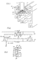
- Fig. 1 eine perspektivische Ansicht eines Fensterrahmenendes mit einer von einem Klotzteil getragenen Glasscheibe,
- Fig. 2 eine Aufsicht auf ein Klotzteil,
- Fig. 3 den Querschnitt III-III der Fig. 2,
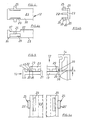
- Fig. 4 eine Aufsicht ähnlich Fig. 2 auf ein Ende einer weiteren Ausführungsform eines Klotzteils,
- Fig. 4a das Klotzteil der Fig. 4 um 90° nach unten geklappt,
- Fig. 4b das Klotzteil der Fig. 4 um 90° nach rechts geklappt,
- Fig. 5 eine weitere Ausführungsform eines Klotzteils, eingesetzt in die Nut eines Rahmenprofils, und
- Fig. 5a das Ende des um 90° nach unten geklappten Klotzteils der Fig. 5.
- In Fig. 1 ist ein Rahmenprofil 10 dargestellt, das eine Isolierglasscheibe 11 trägt, die über ein Klotzteil 12 auf einer Profilwand bzw. einem Nutengrund 13 vertikal abgestützt ist. Zur Halterung der Glasscheibe 11 dienen eine Profilleiste 14 auf einer Seite der Isolierglasscheibe 11 und eine Glashalteleiste 15 auf der anderen Seite der Isolierglasscheibe 11. Die Glashalteleiste 15 ist mit einer Verbindungsrippe 16 in die Profilwand 13 des Rahmenprofils 10 eingerastet. Die seitliche Abstützung der Isolierglasscheibe 11 erfolgt über elastische Dichtungsleisten 17, die mit der Profilleiste 14 und der Glashalteleiste 15 über Verbindungsrippen 18 durch Verrastung in entsprechenden Verbindungsrillen befestigt sind.
- Trotz der Dichtungsleisten 17 kann es im Raum zwischen der Isolierglasscheibe 11 und dem Rahmenprofil 10 unterhalb der Dichtungsleisten 17 zu Kondenswasseranfall kommen oder zu Ansammlung von infolge schadhafter oder nicht sachgemäß angebrachter Dichtungsleisten 17 auftretendem Leckwasser. Es sind daher im Rahmenprofil 10 Entwässerungsbohrungen 19 vorgesehen, welche die das anfallende Wasser sammelnde Profilfläche 20 zu entwässern gestatten. Da diese Entwässerungsbohrungen 19 nur in Abständen voneinander angeordnet sind, muß das Wasser zu ihnen fließen können, beispielsweise infolge geringer Neigung der Profilfläche 20 oder infolge von Schwenkbewegungen des Flügels. Damit dieses Abfließen des angefallenen Wassers nicht behindert wird, hat das Klotzteil 12 eine Nut 21, die den Durchfluß grundsätzlich gestattet.
- Die Nut 21 wird von zwei Abstützstegen 22 gebildet, die mit Abstand zueinander an der Unterseite 24 einer Abstützplatte 23 des Klotzteils 12 angeordnet sind. Ihr Abstand voneinander ist so gewählt, daß sie etwa in einer Ebene mit den Einzelscheiben der Isolierglasscheibe 11 liegen, so daß die zwischen den Abstützstegen 22 gelegenen Bereiche der Abstützplatte 23 nicht wesentlich belastet werden, sondern vielmehr die Hauptlast direkt über die Abstützstege 22 abgetragen wird.
- Das Klotzteil 12 ruht mit seinen Abstützstegen 22 auf dem Nutengrund 13 und ist mit Seitenvorsprüngen 25 an den Nutseitenwänden 26 des Rahmenprofils abgestützt. Die Abstützung erfolgt so, daß das Klotzteil 12 klemmt.
- Gemäß Fig. 2 sind insgesamt drei Seitenvorsprünge 25 vorgesehen, einer auf der einen Seitenwand 27 in der Mitte des Klotzteils 12 und zwei in der Nähe der Enden des Klotzteils 12 an der anderen Seitenwand 28. Damit erfolgt eine sichere Lagerung des Klotzteils 12 mit einem minimalen Aufwand an Seitenvorsprüngen und damit an Werkstoff für diese Seitenvorsprünge 25. Andererseits gewährleisten die Seitenvorsprünge 25, daß der Werkstoffaufwand für das Klotzteil 12 jeweils entsprechend den Abständen a der Fig. 2 zwischen den Seitenwänden 26 des Rahmens 10 und den Seitenwänden 27, 28 des Klotzteils 12 entsprechend klein gehalten wird. In diesem Sinne kommt auch hinzu, daß die Seitenvorsprünge 25 in der Plattenebene der Abstützplatte 23 angeordnet sind, sich also nicht auf dem Nutengrund 13 abstützen bzw. in dessen Nähe kommen. Die Seitenvorsprünge 25 können aber auch unterhalb der Plattenebene bzw. Abstützplatte 23 angeordnet sein.
- Es sind Längsschlitze 29 vorhanden, um ein Einfedern der Seitenvorsprünge 25 zu ermöglichen. Diese Längsschlitze 29 sind diesen Seitenvorsprüngen 25 dicht benachbart und befinden sich im dargestellten Fall direkt anschließend an denjenigen Klotzteilbereich 30, der einem Abstützsteg 22 und der Abstützplatte 23 gemeinsam ist. Die Länge 1 des Längsschlitzes 29 übersteigt die Erstreckung des Seitenvorsprungs 25 in Plattenlängsrichtung, also in den Richtungen des Pfeils 31. Außerdem ist der Längsschlitz 29 mit dem zugehörigen Seitenvorsprung 25 symmetrisch quer zur Plattenlängsrichtung angeordnet, also symmetrisch in den Richtungen des Pfeils 33. Ferner ist noch darauf hinzuweisen, daß der Längsschlitz 29 höchstens doppelt so lang ist, wie der Seitenvorsprung 25 über die Abstützplatte 23 seitlich vorsteht.
- Durch die vorbeschriebene Ausbildung des Klotzteils 12 ergibt sich zwischen dem Seitenvorsprung 25 und seinem zugehörigen Längsschlitz 29 beidseitig je ein Verformungsbereich 32 der Abstützplatte 23 und des daran ansetzenden Abstützstegs 22, der in Verbindung mit den Materialeigenschaften des aus Kunststoff bestehenden Klotzteils 12 die Federungswirkung bzw. die Klemmwirkung des Seitenvorsprungs 25 bestimmt. In Fig. 2 ist punktiert eingezeichnet, daß eine engere Nut des Profilrahmens 10 eine entsprechende Einfederung des Seitenvorsprungs 25 bewirkt, der in dieser eingefederten Stellung ebenfalls punktiert dargestellt ist. Es ist ersichtlich, daß sich die Verformungsbereiche 32 maximal verformt haben, so daß der Längsschlitz 29 praktisch geschlossen ist, weil der Seitenvorsprung 25 sich an der nicht verformten Kante 34 der Abstützplatte 23 abstützt. Daraus ist ersichtlich, daß durch eine entsprechende Bemessung der Breite b des Längsschlitzes 29 der maximale Federweg des Seitenvorsprungs 25 begrenzt und damit eine Überlastung des Verformungsbereichs 32 verhindert wird.
- Es versteht sich, daß beim Einklemmen des Klotzteils 12 in eine Nut alle drei Seitenvorsprünge 25 entsprechend den jeweiligen Belastungen einfedern, und daß in Fig. 2 lediglich aus Vereinfachungsgründen auf die Darstellung der Einfederung der unteren beiden Seitenvorsprünge 25 verzichtet wurde.
- Das Klotzteil der Fig. 4 bis 4b besteht aus einer Abstützplatte 23 mit drei in derselben Richtung vorspringenden Abstützstegen 22. Die beiden äußeren Abstützstege tragen an einem Ende des Klotzteils je einen Seitenvorsprung 25, der am Fuß 35 eines Abstützsteges 22 angeordnet ist. Das Einfedern des Seitenvorsprungs 25 wird durch einen Längsschlitz 29 ermöglicht, der denjenigen Klotzteilbereich 30 umfaßt, welcher der Abstützplatte 23 und dem zugehörigen Abstützsteg 22 gemeinsam ist und sich in Richtung auf den Fuß 35 erstreckt. Fig. 4a zeigt, daß der Fuß 35 über die Länge des Längsschlitzes 29 mit einer Aussparung 37 versehen ist, um die Auslenkbarkeit des Seitenvorsprungs 25 bzw. des letzteren tragenden Fußbereichs weiter zu vergrößern. Außerdem trägt diese Aussparung 37, wie auch die erhebliche Höhen- bzw. Quererstreckung des Längsschlitzes 29 zur Werkstoffersparnis bei.
- Das Klotzteil 12 der Fig. 5 ist mit einem nur teilweise dargestellten Rahmenprofil 10 zusammengebaut. Zur gegenseitigen Halterung hat die Nut 21 beidseitig Hinterschneidungen 38, in welche die Seitenvorsprünge 25 des Klotzteils 12 eingreifen.
- Die an der Profilleiste 14 gelegene Hinterschneidung 38 wird von einem Vorsprung 39 gebildet, der einen Abstand h vom Nutengrund 13 hat, ebenso wie der Vorsprung 40 an der gegenüberliegenden Wand 41 der Profilleiste 10.
- Die Dicke der Seitenvorsprünge 25 ist auf die vorgenannte Höhe h abgestimmt, so daß die Vorsprünge 39, 40 von den Seitenvorsprüngen 25 untergriffen werden können. Letztere sind am plattenfernen Ende 36 des jeweils zugehörigen Abstützstegs 22 angeordnet, während sich der Längsschlitz 29 im direkten Anschluß an denjenigen Klotzteilbereich 30 befindet, der der Abstützplatte 23 und dem benachbarten Abstützsteg 22 gemeinsam ist.
- Da die Nutenbreite jedenfalls im Horizontalbereich der Seitenvorsprünge 25 kleiner bemessen ist, als der Abstand der Außenflächen 25′ der Seitenvorsprünge 25 voneinander, müssen letztere einfedern können, wozu die Längsschlitze 29 dienen. Es ergibt sich die in Fig. 5a gepunktet dargestellte Lage der am Einfedern beteiligten Bauteile, nämlich der Seitenvorsprünge 25 und der im Bereich der Längsschlitze 29 gelegenen Teile der Abstützstege 22.
Claims (8)
Priority Applications (1)
| Application Number | Priority Date | Filing Date | Title |
|---|---|---|---|
| AT88118539T ATE62318T1 (de) | 1987-11-11 | 1988-11-08 | Klotzteil zum festsetzen von glasscheiben od. dgl. |
Applications Claiming Priority (2)
| Application Number | Priority Date | Filing Date | Title |
|---|---|---|---|
| DE8715004U DE8715004U1 (de) | 1987-11-11 | 1987-11-11 | Klotzteil zum Festsetzen von Glasscheiben od. dgl. |
| DE8715004U | 1987-11-11 |
Publications (2)
| Publication Number | Publication Date |
|---|---|
| EP0315936A1 true EP0315936A1 (de) | 1989-05-17 |
| EP0315936B1 EP0315936B1 (de) | 1991-04-03 |
Family
ID=6814006
Family Applications (1)
| Application Number | Title | Priority Date | Filing Date |
|---|---|---|---|
| EP88118539A Expired - Lifetime EP0315936B1 (de) | 1987-11-11 | 1988-11-08 | Klotzteil zum Festsetzen von Glasscheiben od. dgl. |
Country Status (4)
| Country | Link |
|---|---|
| EP (1) | EP0315936B1 (de) |
| AT (1) | ATE62318T1 (de) |
| DE (2) | DE8715004U1 (de) |
| ES (1) | ES2021814B3 (de) |
Cited By (8)
| Publication number | Priority date | Publication date | Assignee | Title |
|---|---|---|---|---|
| EP0403439A1 (de) * | 1989-06-13 | 1990-12-19 | Ruggero Rossetto | Einstellbares Verglasungssystem |
| GB2243641A (en) * | 1990-05-02 | 1991-11-06 | Glazpart Ltd | Self-adjusting packing member for glazing |
| EP0523282A1 (de) * | 1991-07-17 | 1993-01-20 | Hans-Dieter Niemann | Abstützteil für Glasscheiben von Fenstern, Türen od. dgl. |
| GB2265408A (en) * | 1992-03-26 | 1993-09-29 | Epwin Group Plc | Support member for a glazing unit in a frame with drainage channels |
| WO1996013647A1 (en) * | 1994-10-31 | 1996-05-09 | Gunnebo Industrier Ab | An arrangement and a method for supporting a sheet member by means of setting blocks in a frame structure |
| DE29820399U1 (de) * | 1998-11-14 | 2000-03-30 | Niemann, Hans Dieter, 50169 Kerpen | Abstützelement einer Glasscheibe |
| WO2008145255A1 (de) * | 2007-05-25 | 2008-12-04 | Rehau Ag + Co | Klotzbrücke sowie gerahmtes flächentragelement mit einer derartigen klotzbrücke |
| CN105442994B (zh) * | 2014-08-06 | 2017-03-01 | 吉田建材(苏州)有限公司 | 门窗用支架简易安装部件、门窗用支架安装结构及门窗 |
Families Citing this family (2)
| Publication number | Priority date | Publication date | Assignee | Title |
|---|---|---|---|---|
| DE4212587A1 (de) * | 1992-04-15 | 1993-10-21 | Wicona Bausysteme | Wärmegedämmtes Verglasungssystem o. dgl. |
| DE4323881C1 (de) * | 1993-07-16 | 1994-10-20 | Wicona Bausysteme Gmbh | Fenster-, Türrahmen oder dergleichen |
Citations (5)
| Publication number | Priority date | Publication date | Assignee | Title |
|---|---|---|---|---|
| DE1683038A1 (de) * | 1967-12-29 | 1971-03-18 | Horbach & Schmitz Gmbh | Steckverbindung,insbesondere fuer Bestandteil von Rahmen bildende Profile |
| DE8315875U1 (de) * | 1983-05-31 | 1984-02-16 | Läken Fensterzubehör GmbH, 4504 Georgsmarienhütte | Fuelleiste fuer entwaesserungsnut in fenster- und tuerfluegelrahmen |
| EP0114220A1 (de) * | 1982-12-23 | 1984-08-01 | Hans-Dieter Niemann | Klotzbrücke zum Festsetzen von Glasscheiben od. dgl. in Tür- oder Fensterrahmen |
| EP0211781A1 (de) * | 1985-07-23 | 1987-02-25 | ARBAN, Société à Responsabilité Limitée | Versperrungsvorrichtung für Isolierverglasungen in Aussenrahmen |
| DE8705528U1 (de) * | 1987-04-14 | 1987-07-09 | Schüring GmbH & Co Fenstertechnologie KG, 5000 Köln | Verklotzungselement aus Kunststoff |
-
1987
- 1987-11-11 DE DE8715004U patent/DE8715004U1/de not_active Expired
-
1988
- 1988-11-08 AT AT88118539T patent/ATE62318T1/de not_active IP Right Cessation
- 1988-11-08 EP EP88118539A patent/EP0315936B1/de not_active Expired - Lifetime
- 1988-11-08 ES ES88118539T patent/ES2021814B3/es not_active Expired - Lifetime
- 1988-11-08 DE DE8888118539T patent/DE3862286D1/de not_active Expired - Lifetime
Patent Citations (5)
| Publication number | Priority date | Publication date | Assignee | Title |
|---|---|---|---|---|
| DE1683038A1 (de) * | 1967-12-29 | 1971-03-18 | Horbach & Schmitz Gmbh | Steckverbindung,insbesondere fuer Bestandteil von Rahmen bildende Profile |
| EP0114220A1 (de) * | 1982-12-23 | 1984-08-01 | Hans-Dieter Niemann | Klotzbrücke zum Festsetzen von Glasscheiben od. dgl. in Tür- oder Fensterrahmen |
| DE8315875U1 (de) * | 1983-05-31 | 1984-02-16 | Läken Fensterzubehör GmbH, 4504 Georgsmarienhütte | Fuelleiste fuer entwaesserungsnut in fenster- und tuerfluegelrahmen |
| EP0211781A1 (de) * | 1985-07-23 | 1987-02-25 | ARBAN, Société à Responsabilité Limitée | Versperrungsvorrichtung für Isolierverglasungen in Aussenrahmen |
| DE8705528U1 (de) * | 1987-04-14 | 1987-07-09 | Schüring GmbH & Co Fenstertechnologie KG, 5000 Köln | Verklotzungselement aus Kunststoff |
Cited By (8)
| Publication number | Priority date | Publication date | Assignee | Title |
|---|---|---|---|---|
| EP0403439A1 (de) * | 1989-06-13 | 1990-12-19 | Ruggero Rossetto | Einstellbares Verglasungssystem |
| GB2243641A (en) * | 1990-05-02 | 1991-11-06 | Glazpart Ltd | Self-adjusting packing member for glazing |
| EP0523282A1 (de) * | 1991-07-17 | 1993-01-20 | Hans-Dieter Niemann | Abstützteil für Glasscheiben von Fenstern, Türen od. dgl. |
| GB2265408A (en) * | 1992-03-26 | 1993-09-29 | Epwin Group Plc | Support member for a glazing unit in a frame with drainage channels |
| WO1996013647A1 (en) * | 1994-10-31 | 1996-05-09 | Gunnebo Industrier Ab | An arrangement and a method for supporting a sheet member by means of setting blocks in a frame structure |
| DE29820399U1 (de) * | 1998-11-14 | 2000-03-30 | Niemann, Hans Dieter, 50169 Kerpen | Abstützelement einer Glasscheibe |
| WO2008145255A1 (de) * | 2007-05-25 | 2008-12-04 | Rehau Ag + Co | Klotzbrücke sowie gerahmtes flächentragelement mit einer derartigen klotzbrücke |
| CN105442994B (zh) * | 2014-08-06 | 2017-03-01 | 吉田建材(苏州)有限公司 | 门窗用支架简易安装部件、门窗用支架安装结构及门窗 |
Also Published As
| Publication number | Publication date |
|---|---|
| ES2021814B3 (es) | 1991-11-16 |
| ATE62318T1 (de) | 1991-04-15 |
| DE8715004U1 (de) | 1988-01-14 |
| EP0315936B1 (de) | 1991-04-03 |
| DE3862286D1 (de) | 1991-05-08 |
Similar Documents
| Publication | Publication Date | Title |
|---|---|---|
| AT402838B (de) | Dichtungsvorrichtung, insbesondere für türflügel | |
| EP0517057B1 (de) | Verkleidung für Rahmen von Fenstern, Türen od.dgl. | |
| EP0243815A2 (de) | Grundrahmen und Verbindungselemente für Displaysysteme | |
| EP0683287A1 (de) | Profilschiene zur Befestigung flächiger Gegenstände | |
| WO1998023138A2 (de) | Schaltschrank mit einer montageplatte | |
| DE3331594C2 (de) | ||
| EP0315936B1 (de) | Klotzteil zum Festsetzen von Glasscheiben od. dgl. | |
| EP0114220B1 (de) | Klotzbrücke zum Festsetzen von Glasscheiben od. dgl. in Tür- oder Fensterrahmen | |
| DE4242589C2 (de) | Anordnung, insbesondere für Schaltschranktür | |
| EP0599051B1 (de) | Abstützteil für Glasscheiben von Fenstern, Türen od. dgl. | |
| EP0523282B1 (de) | Abstützteil für Glasscheiben von Fenstern, Türen od. dgl. | |
| DE2923903C2 (de) | ||
| AT395133B (de) | Tragleiste fuer einen fahrzeug-gepaeckstraeger | |
| DE2606614A1 (de) | Rahmen fuer einen fenster- oder tuerfluegel | |
| DE10147925A1 (de) | Sockel für einen Schaltschrank | |
| DE3033651A1 (de) | Haltevorrichtung fuer stoffbespannbare paneelierte wandungen | |
| DE69510627T2 (de) | Geräteträgereinrichtung Einzubringen auf einen Kabelkanalkörper | |
| CH688115A5 (de) | Vorrichtung zur Aufnahme eines Tafelelements. | |
| DE2703111C3 (de) | ||
| EP0687790A1 (de) | Linearverbinder für hohle Abstandsprofile eines Mehrscheibenisolierglases | |
| DE29913903U1 (de) | Linearverbinder aus Kunststoff für Abstandhalterprofile von Mehrscheibenisoliergläsern | |
| DE7702843U1 (de) | Fuehrungsschiene | |
| DE4336072C2 (de) | Baugruppenträger | |
| DE9217883U1 (de) | Klotzteil zum Festsetzen von Glasscheiben o.dgl. in Nuten von Tür- oder Fensterrahmen | |
| EP0321874B1 (de) | Vorrichtung zur Befestigung von Gehäusen in Öffnungen einer Schalttafel oder einer Rastersystemwand |
Legal Events
| Date | Code | Title | Description |
|---|---|---|---|
| PUAI | Public reference made under article 153(3) epc to a published international application that has entered the european phase |
Free format text: ORIGINAL CODE: 0009012 |
|
| AK | Designated contracting states |
Kind code of ref document: A1 Designated state(s): AT BE CH DE ES FR GB IT LI NL |
|
| 17P | Request for examination filed |
Effective date: 19891031 |
|
| 17Q | First examination report despatched |
Effective date: 19900207 |
|
| GRAA | (expected) grant |
Free format text: ORIGINAL CODE: 0009210 |
|
| AK | Designated contracting states |
Kind code of ref document: B1 Designated state(s): AT BE CH DE ES FR GB IT LI NL |
|
| REF | Corresponds to: |
Ref document number: 62318 Country of ref document: AT Date of ref document: 19910415 Kind code of ref document: T |
|
| GBT | Gb: translation of ep patent filed (gb section 77(6)(a)/1977) | ||
| REF | Corresponds to: |
Ref document number: 3862286 Country of ref document: DE Date of ref document: 19910508 |
|
| ITF | It: translation for a ep patent filed | ||
| ET | Fr: translation filed | ||
| PLBE | No opposition filed within time limit |
Free format text: ORIGINAL CODE: 0009261 |
|
| STAA | Information on the status of an ep patent application or granted ep patent |
Free format text: STATUS: NO OPPOSITION FILED WITHIN TIME LIMIT |
|
| 26N | No opposition filed | ||
| PGFP | Annual fee paid to national office [announced via postgrant information from national office to epo] |
Ref country code: ES Payment date: 19951102 Year of fee payment: 8 |
|
| PG25 | Lapsed in a contracting state [announced via postgrant information from national office to epo] |
Ref country code: ES Free format text: LAPSE BECAUSE OF EXPIRATION OF PROTECTION Effective date: 19961111 |
|
| REG | Reference to a national code |
Ref country code: ES Ref legal event code: FD2A Effective date: 20010301 |
|
| REG | Reference to a national code |
Ref country code: GB Ref legal event code: IF02 |
|
| PG25 | Lapsed in a contracting state [announced via postgrant information from national office to epo] |
Ref country code: IT Free format text: LAPSE BECAUSE OF NON-PAYMENT OF DUE FEES;WARNING: LAPSES OF ITALIAN PATENTS WITH EFFECTIVE DATE BEFORE 2007 MAY HAVE OCCURRED AT ANY TIME BEFORE 2007. THE CORRECT EFFECTIVE DATE MAY BE DIFFERENT FROM THE ONE RECORDED. Effective date: 20051108 |
|
| PGFP | Annual fee paid to national office [announced via postgrant information from national office to epo] |
Ref country code: FR Payment date: 20051110 Year of fee payment: 18 |
|
| PGFP | Annual fee paid to national office [announced via postgrant information from national office to epo] |
Ref country code: CH Payment date: 20051114 Year of fee payment: 18 Ref country code: NL Payment date: 20051114 Year of fee payment: 18 |
|
| PGFP | Annual fee paid to national office [announced via postgrant information from national office to epo] |
Ref country code: AT Payment date: 20051115 Year of fee payment: 18 |
|
| PGFP | Annual fee paid to national office [announced via postgrant information from national office to epo] |
Ref country code: GB Payment date: 20051121 Year of fee payment: 18 |
|
| PGFP | Annual fee paid to national office [announced via postgrant information from national office to epo] |
Ref country code: BE Payment date: 20051216 Year of fee payment: 18 |
|
| PGFP | Annual fee paid to national office [announced via postgrant information from national office to epo] |
Ref country code: DE Payment date: 20060131 Year of fee payment: 18 |
|
| PG25 | Lapsed in a contracting state [announced via postgrant information from national office to epo] |
Ref country code: AT Free format text: LAPSE BECAUSE OF NON-PAYMENT OF DUE FEES Effective date: 20061108 |
|
| PG25 | Lapsed in a contracting state [announced via postgrant information from national office to epo] |
Ref country code: CH Free format text: LAPSE BECAUSE OF NON-PAYMENT OF DUE FEES Effective date: 20061130 Ref country code: LI Free format text: LAPSE BECAUSE OF NON-PAYMENT OF DUE FEES Effective date: 20061130 Ref country code: BE Free format text: LAPSE BECAUSE OF NON-PAYMENT OF DUE FEES Effective date: 20061130 |
|
| PG25 | Lapsed in a contracting state [announced via postgrant information from national office to epo] |
Ref country code: DE Free format text: LAPSE BECAUSE OF NON-PAYMENT OF DUE FEES Effective date: 20070601 Ref country code: NL Free format text: LAPSE BECAUSE OF NON-PAYMENT OF DUE FEES Effective date: 20070601 |
|
| REG | Reference to a national code |
Ref country code: CH Ref legal event code: PL |
|
| GBPC | Gb: european patent ceased through non-payment of renewal fee |
Effective date: 20061108 |
|
| NLV4 | Nl: lapsed or anulled due to non-payment of the annual fee |
Effective date: 20070601 |
|
| REG | Reference to a national code |
Ref country code: FR Ref legal event code: ST Effective date: 20070731 |
|
| PG25 | Lapsed in a contracting state [announced via postgrant information from national office to epo] |
Ref country code: GB Free format text: LAPSE BECAUSE OF NON-PAYMENT OF DUE FEES Effective date: 20061108 |
|
| BERE | Be: lapsed |
Owner name: *NIEMANN HANS-DIETER Effective date: 20061130 |
|
| PG25 | Lapsed in a contracting state [announced via postgrant information from national office to epo] |
Ref country code: FR Free format text: LAPSE BECAUSE OF NON-PAYMENT OF DUE FEES Effective date: 20061130 |