EP0316071A2 - Bohrlochkopfstruktur - Google Patents
Bohrlochkopfstruktur Download PDFInfo
- Publication number
- EP0316071A2 EP0316071A2 EP88309523A EP88309523A EP0316071A2 EP 0316071 A2 EP0316071 A2 EP 0316071A2 EP 88309523 A EP88309523 A EP 88309523A EP 88309523 A EP88309523 A EP 88309523A EP 0316071 A2 EP0316071 A2 EP 0316071A2
- Authority
- EP
- European Patent Office
- Prior art keywords
- housing
- string
- interior
- bushing
- wellhead structure
- Prior art date
- Legal status (The legal status is an assumption and is not a legal conclusion. Google has not performed a legal analysis and makes no representation as to the accuracy of the status listed.)
- Granted
Links
- 238000007789 sealing Methods 0.000 claims abstract description 25
- 238000010273 cold forging Methods 0.000 claims abstract description 20
- 238000005242 forging Methods 0.000 claims description 6
- 239000002184 metal Substances 0.000 claims description 3
- 230000005540 biological transmission Effects 0.000 claims 1
- 210000002832 shoulder Anatomy 0.000 description 23
- 239000000463 material Substances 0.000 description 7
- 238000009434 installation Methods 0.000 description 2
- 238000000034 method Methods 0.000 description 2
- 239000004593 Epoxy Substances 0.000 description 1
- 230000000332 continued effect Effects 0.000 description 1
- 239000012530 fluid Substances 0.000 description 1
- 239000007788 liquid Substances 0.000 description 1
- 239000011159 matrix material Substances 0.000 description 1
- 239000004005 microsphere Substances 0.000 description 1
- 239000000203 mixture Substances 0.000 description 1
- 230000003252 repetitive effect Effects 0.000 description 1
- 238000010080 roll forging Methods 0.000 description 1
- 239000000725 suspension Substances 0.000 description 1
Images



Classifications
-
- F—MECHANICAL ENGINEERING; LIGHTING; HEATING; WEAPONS; BLASTING
- F16—ENGINEERING ELEMENTS AND UNITS; GENERAL MEASURES FOR PRODUCING AND MAINTAINING EFFECTIVE FUNCTIONING OF MACHINES OR INSTALLATIONS; THERMAL INSULATION IN GENERAL
- F16L—PIPES; JOINTS OR FITTINGS FOR PIPES; SUPPORTS FOR PIPES, CABLES OR PROTECTIVE TUBING; MEANS FOR THERMAL INSULATION IN GENERAL
- F16L13/00—Non-disconnectable pipe joints, e.g. soldered, adhesive, or caulked joints
- F16L13/14—Non-disconnectable pipe joints, e.g. soldered, adhesive, or caulked joints made by plastically deforming the material of the pipe, e.g. by flanging, rolling
- F16L13/16—Non-disconnectable pipe joints, e.g. soldered, adhesive, or caulked joints made by plastically deforming the material of the pipe, e.g. by flanging, rolling the pipe joint consisting of overlapping extremities having mutually co-operating collars
- F16L13/166—Deformed by radially expanding an inner part
-
- E—FIXED CONSTRUCTIONS
- E21—EARTH OR ROCK DRILLING; MINING
- E21B—EARTH OR ROCK DRILLING; OBTAINING OIL, GAS, WATER, SOLUBLE OR MELTABLE MATERIALS OR A SLURRY OF MINERALS FROM WELLS
- E21B23/00—Apparatus for displacing, setting, locking, releasing or removing tools, packers or the like in boreholes or wells
- E21B23/04—Apparatus for displacing, setting, locking, releasing or removing tools, packers or the like in boreholes or wells operated by fluid means, e.g. actuated by explosion
- E21B23/0415—Apparatus for displacing, setting, locking, releasing or removing tools, packers or the like in boreholes or wells operated by fluid means, e.g. actuated by explosion using particular fluids, e.g. electro-active liquids
-
- E—FIXED CONSTRUCTIONS
- E21—EARTH OR ROCK DRILLING; MINING
- E21B—EARTH OR ROCK DRILLING; OBTAINING OIL, GAS, WATER, SOLUBLE OR MELTABLE MATERIALS OR A SLURRY OF MINERALS FROM WELLS
- E21B33/00—Sealing or packing boreholes or wells
- E21B33/02—Surface sealing or packing
- E21B33/03—Well heads; Setting-up thereof
- E21B33/04—Casing heads; Suspending casings or tubings in well heads
-
- E—FIXED CONSTRUCTIONS
- E21—EARTH OR ROCK DRILLING; MINING
- E21B—EARTH OR ROCK DRILLING; OBTAINING OIL, GAS, WATER, SOLUBLE OR MELTABLE MATERIALS OR A SLURRY OF MINERALS FROM WELLS
- E21B2200/00—Special features related to earth drilling for obtaining oil, gas or water
- E21B2200/01—Sealings characterised by their shape
Definitions
- the present invention relates to an improved wellhead structure and to the method of assembling such structure.
- Compact wellheads have been used to provide a suspension and sealing system for casing and tubing strings from a single head which reduces the stack-up height and reduces the number of connections required.
- the blowout preventer stack is not removed during installation of the casing and tubing.
- the last string of pipe with the casing hangers attached is run into the well and the casing hangers are landed rather than using slips to support a casing string and cutting the string for the installation of a hanger thereon.
- This system would utilize the slips for support and the elastomeric seals to provide the annulus seal.
- hangers have utilized slips to engage and support the well string.
- U. S. Patent Nos. 2,920,909 and 3,311,168 disclose such structure.
- Other hangers have had an external shoulder which is adapted to seat on an internal housing seat, such as is shown in U. S. Patent Nos. 3,561,527 and 3,797,864.
- Such hangers are provided normally with external threads on their lower ends and have their well strings threaded thereon.
- the present invention relates to an improved wellhead structure in which a casing or tubing string is sealed to the housing without the aid of elastomeric seals and includes an internal bushing to assist providing in the tight gripping and sealing engagement between the string and the housing and provides a substantial inner diameter which is unrestricted except for a landing shoulder included in the structure. Also, the internal bushing used in the cold forging of the string into the housing recess improves the gripping and sealing engagement therebetween.
- the bushing includes a series of projections which alternate with the gripping and sealing projections within the housing recess and in another form includes a resilient annulus between the exterior of the bushing and the interior of the string to ensure the uniform application of pressure against the interior of the string and also permits retraction of the forging tool in instances where large casing is being forged into a housing with a restricted inner diameter.
- an internal landing shoulder is cold forged into tight engagement with the interior of the housing which allows full bore operations to be carried through the housing until the landing shoulder is to be used.
- the present invention relates to an improved wellhead structure in which a savings in height is accomplished without the loss of any sealing ability or the introduction of internal obstructions to the interior of the central bore through the casing.
- This structure is provided as a tieback structure in which the upper end of the casing is cold forged into the interior of a hanger adapted while the casing is being supported on slips and the adaptor is supported by the slip bowl.
- An object of the present invention is to provide an improved wellhead structure in which the upper end of a string is cold forged to the housing with an internal member within the string which allows large diameter operations through the housing.
- Another object is to provide an improved wellhead structure including a landing shoulder cold forged into the interior of the housing with substantial support between the landing shoulder and the housing for the support of load supported by the landing shoulder.
- a further object is to provide an improved wellhead structure in which the pressure of the cold forging is uniformly exerted over the interior of the string which is being forged.
- a still further object is to provide a wellhead structure in which the upper end of the casing is supported on a slip assembly which is supported by the housing landing shoulder and which reduces the vertical extent of the wellhead structure.
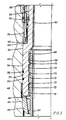
- casing string 10 is positioned within outer well casing 12. Both strings 10 and 12 have been cemented within the well.
- Bushing 14 has been lowered to the position shown wherein its upper outwardly extending flange 16 is in engagement with the upper end of casing string 10 and its exterior surface is positioned within the casing string 10 as shown.
- Housing 18 has been lowered onto flange 16 of bushing 14 and the top of the outer well casing 12 and its depending portion is positioned in close surrounding relationship to the exterior of casing string 10 and its outer downwardly facing shoulder 20 is seated on the upper end of casing 12 while its inner downwardly facing shoulder 22 is seated on the upper surface of flange 16 of bushing 14.
- Recess 26 is below surface 24 and ends in serrated teeth 28.
- Recess 26 includes inward lands 30 projecting inwardly.
- Bushing 14 includes upper annular body portion 32 from which flange 16 extends outwardly, lower body portion 34 and inner body portion 36 extending between portions 32 and 34. Upper body portion forms upper downwardly facing shoulder 38 and lower body portion forms lower upwardly facing shoulder 40 with resilient annulus 42 positioned between shoulders 38 and 40.
- the exterior of upper body portion 32 includes sharp teeth 32a and the exterior of lower body portion includes sharp teeth 34a as shown.
- FIGURE 2 The completed structure is illustrated in FIGURE 2.
- FIGURES 3 and 4 A modified form of the invention as shown in FIGURES 3 and 4, discloses housing 44 which includes a generally cylindrical interior with upwardly facing landing shoulder 45. Slip bowl 46 is landed on landing shoulder 45 and its slips 48 are in gripping engagement with the exterior of the upper end of casing string 50.
- Annular adaptor 52 includes lower section 54 having cylindrical exterior surface 55 with suitable resilient seals 56 for sealing against the interior of housing 44 and lower recess 58 on its interior and upper section 60 having outer recess 62 which ends in upwardly facing shoulder 64 and external threads 66 at its upper end.
- This contour of the interior of lower section 54 in recess 58 includes upper sharp teeth 68, intermediate lands 70 and grooves 72 and lower sharp teeth 74.
- Adaptor 52 is preferably positioned with metal-to-metal seal 76 and seal latch 78 in position within recess 62. Latch 78 and seal 76 are set by the downward movement of sleeve 80 which is in threaded engagement with external threads 66. It is generally considered proper procedure to set seal 76 and latch 78 after adaptor 52 has been landed and casing string 50 has been cold forged against the interior of recess 58 as hereinafter explained.
- a suitable forging tool (not shown) is lowered through adaptor 52 and the string (not shown) on which it is run into the interior of the upper end of casing string 50.
- the tool when in proper position exerts sufficient radial outward pressure on the interior of casing string 50 so that it is deformed into tight sealing and gripping engagement with teeth 68 and 74 and with lands 70 so that any loading from casing string 50 or on adaptor 52 is transferred through slip bowl 48 to landing shoulder 46.
- the result of this deformation from radial cold forging of the upper end of casing string into its recess is illustrated in FIGURE 4. In this configuration, the reduction the height of the wellhead structure is sufficient to be very advantageous.
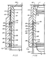
- housing 100 has a lower interior which includes lower sharp, closely spaced teeth 104, intermediate lands 106 and grooves 108 and upper sharp, closely spaced teeth 110.
- the upper end of string 102 is positioned slightly above upper teeth 110.
- the lower exterior of housing 100 includes tapered surface 112 which can be used for engagement with a landing shoulder (not shown).
- the upper exterior includes recess 114 in which a sealing means is to be positioned for sealing the annulus between the interior of the wellhead structure surrounding housing 100 and the exterior of housing 100.
- the upper interior portion of housing 100 includes heavy teeth 116 having repetitive profiles which are adapted to mate with teeth 118 on the exterior of hanger 98 upon completion of the cold forging step as hereinafter described.
- volume compensating material 119 is positioned in the grooves between teeth 116 and 118 to avoid problems which can be encountered during the forging step as a result of well fluids being trapped in such grooves.
- Volume compensating material 119 is preferably microspheres in an epoxy matrix but can be any other suitable materials.
- Hanger 98 includes a lower external recess 120 in which upper sharp, closely spaced teeth 122, intermediate lands 124 and grooves 126 and lower sharp, closely spaced teeth 128 are positioned.
- Shoulder 130 at the upper end of recess 120 faces downwardly and lands on the upper end of string 102 as shown.
- the position of lands 124 is carefully selected to be positioned during the cold forging step approximately mid way between lands 106 on the interior of housing 100. It is believed that this relative positioning of the two sets of lands provides an improved tighter gripping and sealing engagement between housing 100 and string 102 and between hanger 98 and string 102.
- the greater deformation of the cold forged portion of string 102 is shown in FIGURE 6.
- the cold forging step as seen from FIGURE 6 has forged hanger 98 outwardly so that its external teeth 118 are in tight gripping and supporting engagement with teeth 116 on the interior of housing 100.
- the upper end of hanger 98 is tapered upwardly and outwardly to form seat 132.
- the exterior of housing 100 includes sealing recess 114 in which suitable sealing means is positioned to provide a seal bridging the annular space between the exterior of recess 100a and the interior surface of the well member (not shown) surrounding housing 100.
- housing 134 is positioned in surrounding relationship to the upper portion of string 136 and its lower shoulder 138 has landed thereon. In this position full bore operations can also be continued through housing 134 until it is desired to provide the hanger shoulder on its interior for subsequent operations. At such time hanger ring 140 is lowered into position within housing 134 so that the heavy teeth 142 on its exterior surface are facing the heavy teeth 144 on the interior of housing 134 and ready for interengagement between such teeth.
- volume compensating material 146 is positioned in the grooves between heavy teeth 144 to avoid problems of having liquid trapped in the grooves during the cold forging step.
- Material 146 preferably has the same composition as material 119.
Landscapes
- Engineering & Computer Science (AREA)
- Life Sciences & Earth Sciences (AREA)
- Geology (AREA)
- Mining & Mineral Resources (AREA)
- Physics & Mathematics (AREA)
- Environmental & Geological Engineering (AREA)
- Fluid Mechanics (AREA)
- General Life Sciences & Earth Sciences (AREA)
- Geochemistry & Mineralogy (AREA)
- General Engineering & Computer Science (AREA)
- Mechanical Engineering (AREA)
- Earth Drilling (AREA)
- Excavating Of Shafts Or Tunnels (AREA)
- Supporting Of Heads In Record-Carrier Devices (AREA)
- Separation By Low-Temperature Treatments (AREA)
- Gasket Seals (AREA)
- Printers Or Recording Devices Using Electromagnetic And Radiation Means (AREA)
- Chair Legs, Seat Parts, And Backrests (AREA)
- Golf Clubs (AREA)
- Bridges Or Land Bridges (AREA)
- Pharmaceuticals Containing Other Organic And Inorganic Compounds (AREA)
- Paper (AREA)
- Steroid Compounds (AREA)
Priority Applications (2)
| Application Number | Priority Date | Filing Date | Title |
|---|---|---|---|
| AT88309523T ATE92585T1 (de) | 1987-11-11 | 1988-10-12 | Bohrlochkopfstruktur. |
| EP92202030A EP0510778B1 (de) | 1987-11-11 | 1988-10-12 | Bohrlochkopf |
Applications Claiming Priority (4)
| Application Number | Priority Date | Filing Date | Title |
|---|---|---|---|
| GB878726356A GB8726356D0 (en) | 1987-11-11 | 1987-11-11 | Wellhead tieback system |
| GB8726356 | 1987-11-11 | ||
| US07/136,986 US4869319A (en) | 1987-11-11 | 1987-12-23 | Wellhead structure |
| US136986 | 1987-12-23 |
Related Child Applications (2)
| Application Number | Title | Priority Date | Filing Date |
|---|---|---|---|
| EP92202030.0 Division-Into | 1988-10-12 | ||
| EP92202030A Division-Into EP0510778B1 (de) | 1987-11-11 | 1988-10-12 | Bohrlochkopf |
Publications (3)
| Publication Number | Publication Date |
|---|---|
| EP0316071A2 true EP0316071A2 (de) | 1989-05-17 |
| EP0316071A3 EP0316071A3 (en) | 1989-12-20 |
| EP0316071B1 EP0316071B1 (de) | 1993-08-04 |
Family
ID=26293012
Family Applications (1)
| Application Number | Title | Priority Date | Filing Date |
|---|---|---|---|
| EP88309523A Expired - Lifetime EP0316071B1 (de) | 1987-11-11 | 1988-10-12 | Bohrlochkopfstruktur |
Country Status (9)
| Country | Link |
|---|---|
| EP (1) | EP0316071B1 (de) |
| JP (1) | JPH01151691A (de) |
| AT (1) | ATE132225T1 (de) |
| AU (1) | AU613971B2 (de) |
| BR (1) | BR8805879A (de) |
| CA (1) | CA1320436C (de) |
| DE (2) | DE3854844T2 (de) |
| MX (1) | MX170557B (de) |
| NO (1) | NO300339B1 (de) |
Cited By (4)
| Publication number | Priority date | Publication date | Assignee | Title |
|---|---|---|---|---|
| AU613971B2 (en) * | 1987-11-11 | 1991-08-15 | Cooper Cameron Corporation | Wellhead structure and method of assembling same |
| EP0570178A1 (de) * | 1992-05-11 | 1993-11-18 | Cooper Cameron Corporation | Rohrverbindung, Werkzeug und Verfahren zur Herstellung |
| WO2003002846A1 (en) * | 2001-06-29 | 2003-01-09 | Wood Group Pressure Control Limited | Hanger assembly |
| US8505636B2 (en) | 2011-07-29 | 2013-08-13 | Douglas Wade Schepp | Wellhead assembly having a nested tubing head |
Family Cites Families (13)
| Publication number | Priority date | Publication date | Assignee | Title |
|---|---|---|---|---|
| US2134311A (en) * | 1936-05-22 | 1938-10-25 | Regan Forge & Engineering Comp | Method and apparatus for suspending and sealing well casings |
| US2920909A (en) * | 1958-05-12 | 1960-01-12 | Cameron Iron Works Inc | Hanging apparatus |
| US3311168A (en) * | 1964-12-04 | 1967-03-28 | Gray Tool Co | Well head assembly with means for effecting a preloaded seal |
| US3432916A (en) * | 1966-04-18 | 1969-03-18 | Up Right Inc | Method for making a joint for hardened aluminum tubing |
| US3561527A (en) * | 1968-11-01 | 1971-02-09 | Vetco Offshore Ind Inc | Hydraulically set casing hanger apparatus and packing sleeve |
| US3797864A (en) * | 1971-10-28 | 1974-03-19 | Vetco Offshore Ind Inc | Combined metal and elastomer seal |
| US4330144A (en) * | 1974-11-27 | 1982-05-18 | Ridenour Ralph Gaylord | Tube fitting assembly with deformable seal |
| US4411456A (en) * | 1976-04-02 | 1983-10-25 | Martin Charles F | Apparatus, methods, and joints for connecting tubular members |
| GB2057615B (en) * | 1978-02-01 | 1982-09-15 | Fischer Castings Ltd | Pipe fitting |
| IT1131143B (it) * | 1980-05-06 | 1986-06-18 | Nuovo Pignone Spa | Metodo perfezionato per la giunzione a tenuta di un manicotto flangiato ad una tubazione,particolarmente indicato per riparare tubazioni sottomarine posate a grandi profondita' |
| IT1200616B (it) * | 1985-05-03 | 1989-01-27 | Nuovo Pignone Spa | Sistema perfezionato di connessione sottomarina tra le zampe di una piattaforma ed i relativi pali di fondazione |
| GB8726356D0 (en) * | 1987-11-11 | 1987-12-16 | Cameron Iron Works Inc | Wellhead tieback system |
| MX170557B (es) * | 1987-11-11 | 1993-08-31 | Cameron Iron Works Inc | Estructura de cabeza de pozo y metodo para ensamlar la misma |
-
1988
- 1988-09-09 MX MX1373088A patent/MX170557B/es unknown
- 1988-10-12 DE DE3854844T patent/DE3854844T2/de not_active Expired - Fee Related
- 1988-10-12 DE DE88309523T patent/DE3882908T2/de not_active Expired - Fee Related
- 1988-10-12 AT AT92202030T patent/ATE132225T1/de not_active IP Right Cessation
- 1988-10-12 EP EP88309523A patent/EP0316071B1/de not_active Expired - Lifetime
- 1988-10-27 AU AU24444/88A patent/AU613971B2/en not_active Ceased
- 1988-11-08 CA CA000582499A patent/CA1320436C/en not_active Expired - Lifetime
- 1988-11-09 JP JP63283545A patent/JPH01151691A/ja active Pending
- 1988-11-10 NO NO885012A patent/NO300339B1/no unknown
- 1988-11-10 BR BR888805879A patent/BR8805879A/pt not_active IP Right Cessation
Cited By (4)
| Publication number | Priority date | Publication date | Assignee | Title |
|---|---|---|---|---|
| AU613971B2 (en) * | 1987-11-11 | 1991-08-15 | Cooper Cameron Corporation | Wellhead structure and method of assembling same |
| EP0570178A1 (de) * | 1992-05-11 | 1993-11-18 | Cooper Cameron Corporation | Rohrverbindung, Werkzeug und Verfahren zur Herstellung |
| WO2003002846A1 (en) * | 2001-06-29 | 2003-01-09 | Wood Group Pressure Control Limited | Hanger assembly |
| US8505636B2 (en) | 2011-07-29 | 2013-08-13 | Douglas Wade Schepp | Wellhead assembly having a nested tubing head |
Also Published As
| Publication number | Publication date |
|---|---|
| MX170557B (es) | 1993-08-31 |
| JPH01151691A (ja) | 1989-06-14 |
| DE3854844T2 (de) | 1996-05-23 |
| CA1320436C (en) | 1993-07-20 |
| EP0316071A3 (en) | 1989-12-20 |
| NO885012D0 (no) | 1988-11-10 |
| DE3882908D1 (de) | 1993-09-09 |
| NO300339B1 (no) | 1997-05-12 |
| AU2444488A (en) | 1989-05-11 |
| NO885012L (no) | 1989-05-12 |
| DE3854844D1 (de) | 1996-02-08 |
| DE3882908T2 (de) | 1993-11-18 |
| AU613971B2 (en) | 1991-08-15 |
| ATE132225T1 (de) | 1996-01-15 |
| BR8805879A (pt) | 1989-08-01 |
| EP0316071B1 (de) | 1993-08-04 |
Similar Documents
| Publication | Publication Date | Title |
|---|---|---|
| US4488740A (en) | Breech block hanger support | |
| US4615544A (en) | Subsea wellhead system | |
| AU606428B2 (en) | Subsea casing hanger packoff assembly | |
| US4842061A (en) | Casing hanger packoff with C-shaped metal seal | |
| US4550782A (en) | Method and apparatus for independent support of well pipe hangers | |
| US7740061B2 (en) | Externally activated seal system for wellhead | |
| CA1222205A (en) | Emergency release for subsea tool | |
| US4794988A (en) | Surface wellhead | |
| AU645496B2 (en) | Casing head connector | |
| EP0290114A2 (de) | Steigrohrpacker | |
| US4416472A (en) | Holddown and packoff apparatus | |
| EP0289108A2 (de) | Bohrlochkopfaufhängung und -abdichtung | |
| EP0289104A2 (de) | Ringabdichtung für einen Bohrlochkopf | |
| US4869319A (en) | Wellhead structure | |
| US5044442A (en) | Casing hanger running tool using annulus pressure | |
| US5605194A (en) | Independent screwed wellhead with high pressure capability and method | |
| US4171018A (en) | Tubing hanger assembly and method of landing and locking | |
| GB2150173A (en) | Torque multiplier subsea tool | |
| US5159982A (en) | Double walled riser | |
| US6834718B2 (en) | Casing head connector with landing base | |
| US5094297A (en) | Casing weight set seal ring | |
| US3188118A (en) | Pipe holding apparatus | |
| GB2114631A (en) | Breech block hanger support | |
| EP0316071A2 (de) | Bohrlochkopfstruktur | |
| US4892149A (en) | Method of securing a tubular member within an annular well member, the combined well structure and the tool |
Legal Events
| Date | Code | Title | Description |
|---|---|---|---|
| PUAI | Public reference made under article 153(3) epc to a published international application that has entered the european phase |
Free format text: ORIGINAL CODE: 0009012 |
|
| AK | Designated contracting states |
Kind code of ref document: A2 Designated state(s): AT DE FR GB NL |
|
| PUAL | Search report despatched |
Free format text: ORIGINAL CODE: 0009013 |
|
| RAP1 | Party data changed (applicant data changed or rights of an application transferred) |
Owner name: CAMERON IRON WORKS USA, INC. (A DELAWARE CORP.) |
|
| AK | Designated contracting states |
Kind code of ref document: A3 Designated state(s): AT DE FR GB NL |
|
| 17P | Request for examination filed |
Effective date: 19900525 |
|
| RAP1 | Party data changed (applicant data changed or rights of an application transferred) |
Owner name: COOPER INDUSTRIES INC. |
|
| 17Q | First examination report despatched |
Effective date: 19910610 |
|
| GRAA | (expected) grant |
Free format text: ORIGINAL CODE: 0009210 |
|
| AK | Designated contracting states |
Kind code of ref document: B1 Designated state(s): AT DE FR GB NL |
|
| REF | Corresponds to: |
Ref document number: 92585 Country of ref document: AT Date of ref document: 19930815 Kind code of ref document: T |
|
| XX | Miscellaneous (additional remarks) |
Free format text: TEILANMELDUNG 92202030.0 EINGEREICHT AM 12/10/88. |
|
| REF | Corresponds to: |
Ref document number: 3882908 Country of ref document: DE Date of ref document: 19930909 |
|
| ET | Fr: translation filed | ||
| PLBE | No opposition filed within time limit |
Free format text: ORIGINAL CODE: 0009261 |
|
| STAA | Information on the status of an ep patent application or granted ep patent |
Free format text: STATUS: NO OPPOSITION FILED WITHIN TIME LIMIT |
|
| 26N | No opposition filed | ||
| PGFP | Annual fee paid to national office [announced via postgrant information from national office to epo] |
Ref country code: FR Payment date: 19951020 Year of fee payment: 8 |
|
| PGFP | Annual fee paid to national office [announced via postgrant information from national office to epo] |
Ref country code: DE Payment date: 19951027 Year of fee payment: 8 |
|
| REG | Reference to a national code |
Ref country code: GB Ref legal event code: 732E |
|
| PGFP | Annual fee paid to national office [announced via postgrant information from national office to epo] |
Ref country code: AT Payment date: 19960924 Year of fee payment: 9 |
|
| PG25 | Lapsed in a contracting state [announced via postgrant information from national office to epo] |
Ref country code: FR Effective date: 19970630 |
|
| PG25 | Lapsed in a contracting state [announced via postgrant information from national office to epo] |
Ref country code: DE Effective date: 19970701 |
|
| REG | Reference to a national code |
Ref country code: FR Ref legal event code: ST |
|
| PG25 | Lapsed in a contracting state [announced via postgrant information from national office to epo] |
Ref country code: AT Free format text: LAPSE BECAUSE OF NON-PAYMENT OF DUE FEES Effective date: 19971012 |
|
| REG | Reference to a national code |
Ref country code: GB Ref legal event code: IF02 |
|
| PGFP | Annual fee paid to national office [announced via postgrant information from national office to epo] |
Ref country code: NL Payment date: 20020919 Year of fee payment: 15 |
|
| PG25 | Lapsed in a contracting state [announced via postgrant information from national office to epo] |
Ref country code: NL Free format text: LAPSE BECAUSE OF NON-PAYMENT OF DUE FEES Effective date: 20040501 |
|
| NLV4 | Nl: lapsed or anulled due to non-payment of the annual fee |
Effective date: 20040501 |
|
| PGFP | Annual fee paid to national office [announced via postgrant information from national office to epo] |
Ref country code: GB Payment date: 20070918 Year of fee payment: 20 |
|
| REG | Reference to a national code |
Ref country code: GB Ref legal event code: PE20 Expiry date: 20081011 |
|
| PG25 | Lapsed in a contracting state [announced via postgrant information from national office to epo] |
Ref country code: GB Free format text: LAPSE BECAUSE OF EXPIRATION OF PROTECTION Effective date: 20081011 |