EP0316132A2 - Générateur de vapeur - Google Patents
Générateur de vapeur Download PDFInfo
- Publication number
- EP0316132A2 EP0316132A2 EP88310476A EP88310476A EP0316132A2 EP 0316132 A2 EP0316132 A2 EP 0316132A2 EP 88310476 A EP88310476 A EP 88310476A EP 88310476 A EP88310476 A EP 88310476A EP 0316132 A2 EP0316132 A2 EP 0316132A2
- Authority
- EP
- European Patent Office
- Prior art keywords
- water
- burner
- combustion chamber
- air
- generator
- Prior art date
- Legal status (The legal status is an assumption and is not a legal conclusion. Google has not performed a legal analysis and makes no representation as to the accuracy of the status listed.)
- Ceased
Links
- XLYOFNOQVPJJNP-UHFFFAOYSA-N water Substances O XLYOFNOQVPJJNP-UHFFFAOYSA-N 0.000 claims abstract description 60
- 238000002485 combustion reaction Methods 0.000 claims abstract description 36
- 239000007921 spray Substances 0.000 claims abstract description 30
- 239000007789 gas Substances 0.000 claims abstract description 11
- 238000010791 quenching Methods 0.000 claims abstract description 8
- 230000000171 quenching effect Effects 0.000 claims abstract description 8
- 238000009834 vaporization Methods 0.000 claims abstract description 8
- 230000008016 vaporization Effects 0.000 claims abstract description 8
- 239000000446 fuel Substances 0.000 claims description 24
- 239000003570 air Substances 0.000 claims description 12
- 239000012080 ambient air Substances 0.000 claims 1
- UGFAIRIUMAVXCW-UHFFFAOYSA-N Carbon monoxide Chemical compound [O+]#[C-] UGFAIRIUMAVXCW-UHFFFAOYSA-N 0.000 abstract description 8
- 229910002091 carbon monoxide Inorganic materials 0.000 abstract description 8
- 239000004567 concrete Substances 0.000 description 9
- 239000000203 mixture Substances 0.000 description 7
- 239000000567 combustion gas Substances 0.000 description 6
- ATUOYWHBWRKTHZ-UHFFFAOYSA-N Propane Chemical compound CCC ATUOYWHBWRKTHZ-UHFFFAOYSA-N 0.000 description 4
- VNWKTOKETHGBQD-UHFFFAOYSA-N methane Chemical compound C VNWKTOKETHGBQD-UHFFFAOYSA-N 0.000 description 4
- 238000000034 method Methods 0.000 description 2
- 239000003345 natural gas Substances 0.000 description 2
- 239000001294 propane Substances 0.000 description 2
- 238000011144 upstream manufacturing Methods 0.000 description 2
- 230000015572 biosynthetic process Effects 0.000 description 1
- 230000006835 compression Effects 0.000 description 1
- 238000007906 compression Methods 0.000 description 1
- 238000003780 insertion Methods 0.000 description 1
- 230000037431 insertion Effects 0.000 description 1
- 239000011178 precast concrete Substances 0.000 description 1
- 239000011513 prestressed concrete Substances 0.000 description 1
- 239000011819 refractory material Substances 0.000 description 1
- 230000001105 regulatory effect Effects 0.000 description 1
- 230000000717 retained effect Effects 0.000 description 1
- 238000005507 spraying Methods 0.000 description 1
Images

Classifications
-
- F—MECHANICAL ENGINEERING; LIGHTING; HEATING; WEAPONS; BLASTING
- F22—STEAM GENERATION
- F22B—METHODS OF STEAM GENERATION; STEAM BOILERS
- F22B27/00—Instantaneous or flash steam boilers
-
- F—MECHANICAL ENGINEERING; LIGHTING; HEATING; WEAPONS; BLASTING
- F22—STEAM GENERATION
- F22B—METHODS OF STEAM GENERATION; STEAM BOILERS
- F22B1/00—Methods of steam generation characterised by form of heating method
- F22B1/22—Methods of steam generation characterised by form of heating method using combustion under pressure substantially exceeding atmospheric pressure
- F22B1/26—Steam boilers of submerged-flame type, i.e. the flame being surrounded by, or impinging on, the water to be vaporised
Definitions
- the present invention is an instant steam generator.
- the invention provides a compact unit having no boiler which can be used on site to generate various qualities of steam for a variety of applications.
- the invention has particular application for curing prestressed and precast concrete and generally for the standard curing of concrete products such as blocks or pipes.
- the concrete curing process generates heat, which tends to warm up the inside of concrete products.
- a desirable feature for an instant steam generator is that is has a low carbon monoxide output.
- a low carbon monoxide output is essential where the steam generator is operated in an enclosed facility, for example, in a concrete products plant or in a mine, in order to meet typical government regulations for worker exposure to carbon monoxide.
- the invention employs a unique combustion chamber and water vaporization combination whereby the combustion chamber is cooled by a surrounding jacket of circulating water, and the outflow of water from the jacket is used as the source of water to be vaporized by combustion gases from a burner located at one end of the chamber.
- the present arrangement differs from that previously known, for example as described in U.S. Patent No. 4,211,071-Wyatt, July 8, 1980, by introducing a spray of water countercurrently to the stream of combustion gases exiting the combustion chamber. This arrangement creates a great deal of turbulence in the area surrounding the water spray thus ensuring instant and thorough vaporization of the spray by the combustion gases.
- prior devices e.g.
- a steam generator comprising a water jacketed combustion chamber having an inlet and an outlet for the circulation of water through the jacket and having first and second ends.
- a burner is positioned in the first end of the combustion chamber.
- Means are provided for delivering pressurized air and fuel to the burner so that the burner may produce a flame extending toward the second end of the combustion chamber.
- a water spray nozzle is positioned at the second end of the combustion chamber remote from the burner flame, said nozzle being connected to the outlet of the jacket and being adapted to spray water countercurrently into a stream of hot gases from the burner flame thereby creating steam without quenching the flame.
- a discharge conduit is connected to the second end of the combustion chamber for conveying the steam so generated.
- the present invention employs a unique arrangement in which the water is sprayed countercurrently to the flow of hot gases, and the water spray nozzle can be pointed directly at the burner.
- This arrangement is contrary to conventional teachings which specify that the water should be sprayed away from the flame to avoid flame quenching.
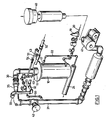
- the steam generator of the present invention comprises a combustion chamber 10 having a burner 11 at one end and a water spray nozzle 12 at the other end.
- the chamber 10 is provided with a water jacket 15 (Fig. 2) having a jacket inlet 16 near the lower end of the chamber 10 and a jacket outlet 17 near the upper or burner end of the chamber 10.
- Water is circulated throught the jacket 15 at a rate of circulation governed by water pressure controls 19 which are readily available and which are inserted into the water inlet line 20.
- Water exiting the jacket 15 proceeds through the jacket outlet 17 and a pipe 22 to the water spray nozzle 12 which is in turn located within a steam outlet line or discharge conduit 24.
- the combustion chamber 10 is sized to enable complete combustion of the fuel by the flame of the burner 11 within the confines of the chamber 10.
- a zone 25 in the lower portion ofthe combustion chamber 10 for the hot exhaust gases of combustion with fuel combustion occurring to the fullest extent allowed by the mechanics of the burner 11 in a zone 26 in the upper portion of the chamber 10 about the flame.
- the burner 11 is an oil burner or preferably a burner of the type which burns a pressurized gaseous fuel mixture such as air and natural gas or propane. Accordingly, the burner 11 is provided with an inlet conduit 30 comprising a larger diameter inlet air pipe 31 for pressurized air, into which is joined a fuel pipe 32 of a lesser diameter. The junction point 33 of the pipes 31 and 32 is just upstream of a venturi 35. The gaseous fuel mixture is throughly mixed by flowing through the venturi 35 thereby ensuring even combustion at the burner head 11 and affording good control of the heat output therefrom.
- a pressurized gaseous fuel mixture such as air and natural gas or propane. Accordingly, the burner 11 is provided with an inlet conduit 30 comprising a larger diameter inlet air pipe 31 for pressurized air, into which is joined a fuel pipe 32 of a lesser diameter.
- the junction point 33 of the pipes 31 and 32 is just upstream of a venturi 35.
- the gaseous fuel mixture is throughly mixed by flowing through the venturi 35
- the air supplied to the inlet air pipe 31 is pressurized in a conventional manner by drawing air in through a filter 40 and passing it through a blower 41 or other well known compression means.
- Pressure in the inlet air pipe 31 may be regulated by use of an appropriate air pressure valve 42, and pressure in the fuel pipe 32 may be controlled by a conventional fuel valve 43.
- the valves 42 and 43 By adjustment of the valves 42 and 43, the pressure and composition of the fuel mixture can be varied as desired.
- Ignition of the burner 11 may conveniently be accomplished by use of a pilot 49 located adjacent the head of the burner 11.
- the pilot 49 may receive a fuel mixture from feeder lines 50 and 51 taken from the main fuel pipe 32 and the inlet air pipe 31.
- the feeder lines 50 and 51 tap the main pipes 31 and 32 at points upstream of the respective valves 42 and 43.
- the feeder lines 50 and 51 are also provided with valves 53 and 54 so that the desired combustion gas mixture and pressure can be provided to the pilot 49.
- any of a number of different kinds of burners would be suitable for use in the present invention. Since the steam generated by the present device contains the exhaust from the burner 11, it may be particularly desirable in certain applications to choose a burner 11 which produces a low level of carbon monoxide. The low carbon monoxide level of the burner 11 will be retained during the steam generating process using the present device, because there is no flame quenching produced by the contercurrent spray of water from the nozzle 12. Likewise, the foregoing description of the fuel and air supply means is illustrative and may be varied with the type of burner used. It will also be apparent to those skilled in this art that central control means may be employed to coordinate the flows and relative pressures of the fuel, air and water streams for the overall system.
- steam is generated by the mixture of the water spray from the water spray nozzle 12 with the hot combustion gases produced by the burner 11 at the lower end of the combustion chamber 10.
- the spray from the water spray nozzle 12 By causing the spray from the water spray nozzle 12 to be directed countercurrently to the exhaust gases from the burner 11, instant vaporization of the water occurs due to the extreme turbulence and thorough mixing of the opposing streams. Turbulence and mixing of opposing streams may be modified by the insertion of baffles in the combustion chamber 10 and in the steam outlet line 24. The quality of the steam exiting through the steam outlet line 24 may be determined by adjusting the output of the burner 11 and the output of the water spray nozzle 12.
- the relative opposing pressures from the burner 11 and the spray nozzle 12 must be adjusted to enable steam to be generated in the manner described, that is, by vaporization of the water contacting the hot exhaust gases from the burner 11.
- the generation of relatively low pressure steam i.e. 5-20 psi, is accomplished using the invention wherein the water vaporization occurs virtually entirely within the outlet neck 59 located between the lower end of the combustion chamber 11 and the steam outlet line 24.
Landscapes
- Engineering & Computer Science (AREA)
- Physics & Mathematics (AREA)
- Thermal Sciences (AREA)
- Mechanical Engineering (AREA)
- General Engineering & Computer Science (AREA)
- Chemical & Material Sciences (AREA)
- Combustion & Propulsion (AREA)
- Life Sciences & Earth Sciences (AREA)
- Sustainable Development (AREA)
- Sustainable Energy (AREA)
- Heat-Pump Type And Storage Water Heaters (AREA)
Applications Claiming Priority (2)
| Application Number | Priority Date | Filing Date | Title |
|---|---|---|---|
| US12001187A | 1987-11-12 | 1987-11-12 | |
| US120011 | 1987-11-12 |
Publications (2)
| Publication Number | Publication Date |
|---|---|
| EP0316132A2 true EP0316132A2 (fr) | 1989-05-17 |
| EP0316132A3 EP0316132A3 (fr) | 1990-03-07 |
Family
ID=22387732
Family Applications (1)
| Application Number | Title | Priority Date | Filing Date |
|---|---|---|---|
| EP88310476A Ceased EP0316132A3 (fr) | 1987-11-12 | 1988-11-08 | Générateur de vapeur |
Country Status (10)
| Country | Link |
|---|---|
| EP (1) | EP0316132A3 (fr) |
| JP (1) | JPH067001B2 (fr) |
| KR (1) | KR890008509A (fr) |
| CN (1) | CN1015200B (fr) |
| AU (1) | AU606764B2 (fr) |
| BR (1) | BR8805886A (fr) |
| CA (1) | CA1267333A (fr) |
| IN (1) | IN168907B (fr) |
| PL (1) | PL275766A1 (fr) |
| ZA (1) | ZA888322B (fr) |
Cited By (7)
| Publication number | Priority date | Publication date | Assignee | Title |
|---|---|---|---|---|
| US5461854A (en) * | 1993-07-07 | 1995-10-31 | Griffin, Jr.; Arthur T. | Combustor cooling for gas turbine engines |
| US6176075B1 (en) | 1993-07-07 | 2001-01-23 | Arthur T. Griffin, Jr. | Combustor cooling for gas turbine engines |
| WO2002065017A1 (fr) * | 2001-02-13 | 2002-08-22 | Chang Gun Shin | Chaudiere echangeuse de chaleur |
| WO2009110841A1 (fr) * | 2008-03-04 | 2009-09-11 | Safesam Ab | Dispositif et procédé pour produire un milieu gazeux comportant de la vapeur |
| RU2488903C1 (ru) * | 2012-05-03 | 2013-07-27 | Рашид Зарифович Аминов | Система сжигания водорода в цикле аэс с регулированием температуры водород-кислородного пара |
| KR101381037B1 (ko) * | 2012-10-05 | 2014-04-04 | 주식회사 동양매직 | 스팀 파이프의 과열 방지 구조를 갖는 스팀 발생 장치 |
| RU2707182C1 (ru) * | 2019-02-25 | 2019-11-25 | Рашид Зарифович Аминов | Способ повышения мощности двухконтурной АЭС за счет комбинирования с водородным циклом |
Families Citing this family (9)
| Publication number | Priority date | Publication date | Assignee | Title |
|---|---|---|---|---|
| JPH095002A (ja) * | 1995-06-26 | 1997-01-10 | Nobuo Takeno | 使捨物差 |
| KR100524108B1 (ko) * | 2002-05-29 | 2005-10-26 | 임호종 | 스팀 발생 장치 |
| CN102519140B (zh) * | 2011-12-27 | 2014-02-26 | 安徽合协生态环境科技有限公司 | 一种热量供给装置 |
| CN103363508A (zh) * | 2012-04-06 | 2013-10-23 | 梁旭春 | 一种喷雾式蒸汽产生的方法 |
| WO2015120755A1 (fr) * | 2014-02-17 | 2015-08-20 | 王连山 | Dispositif de conversion d'énergie thermique |
| CN105003896B (zh) * | 2015-08-05 | 2017-02-01 | 重庆市大为能源有限公司 | 汽化器 |
| CN107269427A (zh) * | 2017-06-16 | 2017-10-20 | 中创新核(北京)科技有限公司 | 一种内热蒸汽增效发动机 |
| EP4010629B1 (fr) * | 2019-08-09 | 2025-03-05 | General Energy Recovery Inc. | Outil générateur de vapeur |
| KR102326989B1 (ko) | 2021-07-15 | 2021-11-16 | 벽산파워 주식회사 | 스팀 제트 추진 시스템 |
Family Cites Families (6)
| Publication number | Priority date | Publication date | Assignee | Title |
|---|---|---|---|---|
| BE555026A (fr) * | ||||
| DE256576C (fr) * | ||||
| GB333922A (en) * | 1929-04-23 | 1930-08-25 | George Rolfe Stow | Improvements in or relating to steam power plants |
| FR716929A (fr) * | 1931-05-12 | 1931-12-30 | Procédé de production d'un fluide gazeux sous pression | |
| NL6811715A (fr) * | 1968-08-16 | 1970-02-18 | ||
| US4288978A (en) * | 1978-05-19 | 1981-09-15 | Vapor Energy, Inc. | Vapor generator |
-
1988
- 1988-11-02 IN IN917/CAL/88A patent/IN168907B/en unknown
- 1988-11-07 AU AU24771/88A patent/AU606764B2/en not_active Ceased
- 1988-11-07 ZA ZA888322A patent/ZA888322B/xx unknown
- 1988-11-08 EP EP88310476A patent/EP0316132A3/fr not_active Ceased
- 1988-11-09 CN CN88107775A patent/CN1015200B/zh not_active Expired
- 1988-11-09 CA CA000582607A patent/CA1267333A/fr not_active Expired - Lifetime
- 1988-11-10 BR BR888805886A patent/BR8805886A/pt unknown
- 1988-11-10 KR KR1019880014799A patent/KR890008509A/ko not_active Withdrawn
- 1988-11-11 PL PL27576688A patent/PL275766A1/xx unknown
- 1988-11-11 JP JP28661788A patent/JPH067001B2/ja not_active Expired - Lifetime
Cited By (9)
| Publication number | Priority date | Publication date | Assignee | Title |
|---|---|---|---|---|
| US5461854A (en) * | 1993-07-07 | 1995-10-31 | Griffin, Jr.; Arthur T. | Combustor cooling for gas turbine engines |
| US5694761A (en) * | 1993-07-07 | 1997-12-09 | Griffin, Jr.; Arthur T. | Combustor cooling for gas turbine engines |
| US6176075B1 (en) | 1993-07-07 | 2001-01-23 | Arthur T. Griffin, Jr. | Combustor cooling for gas turbine engines |
| WO2002065017A1 (fr) * | 2001-02-13 | 2002-08-22 | Chang Gun Shin | Chaudiere echangeuse de chaleur |
| US6938582B2 (en) | 2001-02-13 | 2005-09-06 | Chang Gun Shin | Heat exchanging type boiler |
| WO2009110841A1 (fr) * | 2008-03-04 | 2009-09-11 | Safesam Ab | Dispositif et procédé pour produire un milieu gazeux comportant de la vapeur |
| RU2488903C1 (ru) * | 2012-05-03 | 2013-07-27 | Рашид Зарифович Аминов | Система сжигания водорода в цикле аэс с регулированием температуры водород-кислородного пара |
| KR101381037B1 (ko) * | 2012-10-05 | 2014-04-04 | 주식회사 동양매직 | 스팀 파이프의 과열 방지 구조를 갖는 스팀 발생 장치 |
| RU2707182C1 (ru) * | 2019-02-25 | 2019-11-25 | Рашид Зарифович Аминов | Способ повышения мощности двухконтурной АЭС за счет комбинирования с водородным циклом |
Also Published As
| Publication number | Publication date |
|---|---|
| PL275766A1 (en) | 1989-07-24 |
| JPH067001B2 (ja) | 1994-01-26 |
| AU2477188A (en) | 1989-05-18 |
| BR8805886A (pt) | 1989-08-01 |
| IN168907B (fr) | 1991-07-06 |
| KR890008509A (ko) | 1989-07-10 |
| CN1033095A (zh) | 1989-05-24 |
| CA1267333A (fr) | 1990-04-03 |
| ZA888322B (en) | 1989-08-30 |
| EP0316132A3 (fr) | 1990-03-07 |
| CN1015200B (zh) | 1991-12-25 |
| JPH01159503A (ja) | 1989-06-22 |
| AU606764B2 (en) | 1991-02-14 |
Similar Documents
| Publication | Publication Date | Title |
|---|---|---|
| US4884529A (en) | Steam generator | |
| EP0316132A2 (fr) | Générateur de vapeur | |
| US4148599A (en) | Method to mix liquid fuels with diluent gas for a gaseous fuel burner | |
| US4838897A (en) | Reformer | |
| US4245980A (en) | Burner for reduced NOx emission and control of flame spread and length | |
| KR940007422A (ko) | 열노즐 연소방법 | |
| EP0141594A3 (fr) | Appareil de chauffage | |
| JPS644081B2 (fr) | ||
| EP0535846B1 (fr) | Brûleur | |
| US4375954A (en) | Oil and gas combination nozzle | |
| US1332684A (en) | Method of furnace-heating | |
| JPS63315814A (ja) | 輝炎燃焼装置 | |
| US3947231A (en) | Pilot light system for lighting a main burner for heating high velocity high pressure turbulent air | |
| SU1574994A1 (ru) | Горелка | |
| US3768964A (en) | Air heater | |
| EP0281269A1 (fr) | Appareil de combustion à gaz | |
| NL1000129C1 (en) | Central heating boiler fired by gas - has forced gas and air mixing venturi system controlled by electronic circuit | |
| US3304987A (en) | Apparatus for heating with natural gas | |
| US297638A (en) | Method of using natural gas as a fuel | |
| US653166A (en) | Open bunsen burner. | |
| US335439A (en) | english | |
| US824338A (en) | Gas heating apparatus. | |
| US3880576A (en) | Method for lighting a main burner for heating high velocity high pressure turbulent air | |
| US2046371A (en) | Combustion apparatus | |
| US2290991A (en) | Fuel combustion method and means |
Legal Events
| Date | Code | Title | Description |
|---|---|---|---|
| PUAI | Public reference made under article 153(3) epc to a published international application that has entered the european phase |
Free format text: ORIGINAL CODE: 0009012 |
|
| AK | Designated contracting states |
Kind code of ref document: A2 Designated state(s): AT BE CH DE ES FR GB GR IT LI LU NL SE |
|
| PUAL | Search report despatched |
Free format text: ORIGINAL CODE: 0009013 |
|
| AK | Designated contracting states |
Kind code of ref document: A3 Designated state(s): AT BE CH DE ES FR GB GR IT LI LU NL SE |
|
| 17P | Request for examination filed |
Effective date: 19900813 |
|
| 17Q | First examination report despatched |
Effective date: 19910131 |
|
| STAA | Information on the status of an ep patent application or granted ep patent |
Free format text: STATUS: THE APPLICATION HAS BEEN REFUSED |
|
| 18R | Application refused |
Effective date: 19920524 |