EP0316135A2 - Production d'images à partir de données tomographiques - Google Patents
Production d'images à partir de données tomographiques Download PDFInfo
- Publication number
- EP0316135A2 EP0316135A2 EP88310480A EP88310480A EP0316135A2 EP 0316135 A2 EP0316135 A2 EP 0316135A2 EP 88310480 A EP88310480 A EP 88310480A EP 88310480 A EP88310480 A EP 88310480A EP 0316135 A2 EP0316135 A2 EP 0316135A2
- Authority
- EP
- European Patent Office
- Prior art keywords
- tomographic data
- tomographic
- imaging system
- data
- dimensional image
- Prior art date
- Legal status (The legal status is an assumption and is not a legal conclusion. Google has not performed a legal analysis and makes no representation as to the accuracy of the status listed.)
- Ceased
Links
Images


Classifications
-
- G—PHYSICS
- G06—COMPUTING OR CALCULATING; COUNTING
- G06T—IMAGE DATA PROCESSING OR GENERATION, IN GENERAL
- G06T17/00—Three-dimensional [3D] modelling for computer graphics
Definitions
- the present invention relates to producing images from tomographic data. It is concerned by way of example with producing a two dimensional representation (hereinafter called a 3D image) of a three dimensional object or surface.
- Tomographic medical imaging employs the collection of data from a plurality of views of a body.
- the views are processed mathematically to produce representations of contiguous cross-sectional images.
- Such cross-sectional images are of great value to the medical diagnostician in a non-invasive investigation of internal body structure.
- the technique employed to collect the data is a matter of indifference to the present invention. Any technique such as, for example, X-ray computed tomography, nuclear magnetic resonance tomography, single-photon emission tomography, positron emission tomography, or ultrasound tomography may serve equally.
- a body to be imaged exists in three dimensions.
- Tomographic devices process data for presentation as a series of contiguous cross-sectional slices along selectable axes through the body.
- Each cross sectional slice is made up of a number of rows and columns of voxels (parallelepiped volumes), each represented by a digitally-stored number related to a computed signal intensity in the voxel.
- voxels parallelepiped volumes
- an array of, for example, 64 slices may each contain 512 by 512 voxels.
- a diagnostician reviews images of a number of individual slices to derive the desired information.
- the diagnostician relies on inferences of the 3D nature of the object derived from interrogating the cross-sectional slices. At times, it is difficult or impossible to attain the required inference from reviewing contiguous slices. In such cases, a synthesized 3D image would be valuable.
- Synthesizing a representation in two dimensions of a 3D image from tomographic data is a two-step process.
- a mathematical description of the desired object is extracted from the tomographic data.
- the image is synthesized from the mathematical description.
- the mathematical description of the object is made up of the union of a large number of surface elements (SURFELS).
- the surfels are operated on by conventional computer graphics software, having its genesis in computer aided design and computer aided manufacturing, to apply surface shading to objects to aid in image interpretation through a synthesized two-dimensional image.
- the computer graphics software projects the surfels onto a rasterized image and determines which pixels of the rasterized image are turned on, and with what intensity or color.
- the shading is lightest for image elements having surface normals along an operator-selected line of sight and successively darker for those elements inclined to the line of sight.
- Image elements having surface normals inclined more than 90 degrees from the selected line of sight are hidden in a 3D object and are suppressed from the display.
- Foreground objects on the line of sight hide background objects.
- the shading gives a realistic illusion of three dimensions. It is thus apparent that the information provided by the surface normals to the line of sight are very important in producing a realistic representation in two dimensions of a 3D object.
- a 3D image is referred to as a 3D image.
- this step is broken down into two subtasks, namely the extraction of the object from the tomographic data, and the fitting of the surface to the extracted object.
- a number of ways are available to do the first subtask. For example, it is possible to search through the signal intensities in the voxels of a slice to discern regions where the material forming the object has sufficient signal contrast with surrounding regions. For example, signal intensities characteristic of bone in X-ray tomography produce striking contrast with surrounding tissue. A threshold may then be applied to the voxels to identify each one in the complete array lying in the desired object from all not in the object.
- a method called the marching cubes method, disclosed in U.S. Patent Application Serial No. 741,390, filed June 5, 1985, (EP-A-204225), overcomes many of the drawbacks of the above-mentioned prior work.
- the disclosure of this referenced patent application is herein incorporated by reference.
- signal values in eight cubically adjacent voxels in the tomographic array are examined for those having a specified relationship to a selected threshold value.
- a binary vector is generated characterizing the manner in which the surface of the object passes through the volume defined by the eight cubically adjacent voxels. Up to four triangular surface elements may be defined in such a volume. Normal vectors to the all surface elements thus discovered are input to computer graphics software for display of a shaded 3D image.
- the marching cubes method is successful in improving the 3D representation of objects derived from tomographic data. It is believed that the 3D image quality produced by surface data calculated from the marching cubes method is improved because the surface normals to the image thus derived are equal to the normalized 3D gradient of the original tomographic data.
- a further technique, called the dividing cubes method, for deriving surface data is disclosed in U.S. Patent Application Serial No. 770,164, filed August 28, 1985 (EP-A-216156).
- the disclosure of this referenced patent application is herein incorporated by reference.
- the dividing cubes method divides the voxel in the tomographic array to values which the computer graphics software can treat as a point for scan conversion onto the raster scan of the 3D image. Surface normals to each point are derived from the normalized gradients of the tomographic data.
- the marching cubes and dividing cubes methods produce an imaging artifact to which the present invention is addressed.
- a mismatch exists between the data available from the marching cubes or dividing cubes method and the data that can be handled by the conventional computer graphics software and hardware. This mismatch is triggered by the disparity between the number of row or columns in a slice (generally equal) and the number of slices.
- the method may define more than one surface element for mapping onto the same pixel in the image.
- the conflicting surface normals may point in different directions.
- the computer graphics software without information to guide it, selects one of the surface normals to apply shading in that location, whether it is correct or not. It has been discovered that this effect produces for instance ring-type artifacts at the top of a 3D image of the human skull.
- An aspect of the invention seeks to provide technique capable of overcoming a drawback of the prior art.
- Another aspect of the invention provides a method and apparatus for adjusting a spatial frequency of a tomographic image to eliminate an artifact of a 3D image generated by a marching cubes method.
- a further aspect of the invention provides a method and apparatus for adjusting a spatial frequency of a tomographic image to eliminate an artifact of a 3D image generated by a dividing cubes method.
- a still further aspect of the invention provides a method and apparatus for convolving tomographic image data with a low-pass filter function to remove artifacts from a 3D image derived therefrom.
- Still another aspect of the present invention provides a display system in which data representing a tomographic image is convolved with a low-pass filter function to reduce the maximum spatial frequency, permitting unique mapping of surface images to a rasterized display.
- the filter function may use linear or other weighting. Re-sampling after the filtering is optional.
- the filtered tomographic data is employed to determine the locations and normal vectors of the surface.
- the locations and normal vectors employed by a computer graphics processor for applying shading in relation to the angle between the normal vector to a surface element and an operator-defined line of sight to the surface.
- an imaging system comprising: means for deriving a mathematical description of a surface of an object from a plurality of slices of tomographic data, a computer graphics processor, the computer graphics processor including means for projecting the surface onto a shaded rasterized two-dimensional image, means for displaying the two-dimensional image, means for convolving the tomographic data with a low-pass filter, and the low-pass filter having a characteristic effective for reducing a maximum spatial frequency in the tomographic data to a value permitting no more than one surface element of the surface to be projected to one pixel in the rasterized two-dimensional image.
- a method for synthesizing an image comprising: deriving a mathematical description of a surface of an object from a plurality of slices of tomographic data, projecting the surface onto a shaded rasterized two-dimensional image, displaying the two-dimensional image, convolving the tomographic data with a low-pass filter, and the low-pass filter including a characteristic effective for reducing a maximum spatial frequency in the tomographic data to a value permitting no more than one surface element of the surface to be projected to one pixel in the rasterized two-dimensional image.
- an imaging system comprising: means for deriving a mathematical description of a surface of an object from a plurality of slices of tomographic data, means for projecting the surface onto a shaded rasterized two-dimensional image, means for convolving the tomographic data with a low-pass filter, and the low-pass filter having a characteristic effective for reducing a maximum spatial frequency in the tomographic data to a value permitting no more than one surface element of the surface to be projected to one pixel in the rasterized two-dimensional image.
- the following description employs the marching cubes method for deriving a surface description of an object from tomographic image data. This selection is for illustration and should not be seen as limiting the invention. Other methods such as, for example, the dividing cubes method may equally serve as part of the environment for the present invention without departing from the spirit and scope thereof.
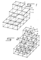
- a part of a tomographic array consisting of a cubic array of cubes 12 defined by nodes 14 connected by edges 16.
- Each node 14 represents a signal amplitude of a voxel of tomographic data and each edge 16 represents the distance from one voxel to its neighbor.
- each node 14 is tested for its relationship to a selected threshold value to determine whether it is above or below the threshold. Then, if two adjacent nodes 14 are found with one node 14 above, the other below, the threshold, the surface of the object must intersect edge 16 somewhere between them at a distance which can be scaled according to the relative signal values. Such intersections 18 are shown as open circles. Lines 20 joining intersections 18 within a cube 12 define a polygonal surface 22. The marching cubes method describes the manner in which lines 20 may be identified. Each polygonal surface 22 is characterized by its intersections 18 and a unit vector directed normal to polygonal surface 22.
- the array of polygonal surfaces 22, isolated from the remainder of tomographic array 10, together with their coordinates and normal vectors, are applied to conventional computer graphics software for shading and display.
- a portion of a line 24 of a conventional rasterized display (not otherwise shown) includes a pixel 26 onto which one element of the 3D surface is to be projected by the computer graphics software. Due to the above-mentioned mismatch between the number of rows or columns in each slice and the number of slices, it is possible that more than one surface element, represented by surface normal vectors 28, 30 and 32, may require projection onto pixel 26. As previously mentioned, the shading (darkness or color) of pixel 26 is adjusted according to the angular relationship between the surface normal of an element and a selected line of sight.
- the shading applied to pixel 26 depends critically on which of surface normal vectors 28, 30 and 32 is selected for controlling the shading of pixel 26. As previously noted, failure to select the correct one produces artifacts in the displayed image.
- a data acquisition system 36 obtains and processes raw data to produce tomographic slice data for application on a line 38 to a low-pass filter 40.
- Data acquisition system 36 may be of any convenient type.
- the filtered row and column data from low-pass filter 40 is applied on a line 42 to a marching cubes processor 44.
- Marching cubes processor 44 calculates the surface coordinates and surface normal vectors as previously described and applies the result on a line 46 to a computer graphics processor 48.
- computer graphics processor 48 calculates and applies shading to the 3D surface according to the inclination of the surface normal vectors at each displayed element of the surface.
- the resulting shaded video is applied on a line 50 to a conventional display 52.
- the spatial frequency of row and column data from data acquisition system 36 is reduced in low-pass filter 40 to a value such that each surface element derived by marching cubes processor 44 generally projects to one, and only one, position on display 52. That is, the maximum spatial frequency of the tomographic data is reduced to a value permitting no more than one surface element to be projected to one pixel in the rasterized image.
- the artifacts previously generated by a computer graphics system employing marching cubes is eliminated. Since the spatial frequency in the output of low-pass filter 40 substantially matches the ability of the computer graphics system to display the 3D image, no resolution is lost in the process. Any greater spatial frequency would not enhance the image but, as described in the preceding, can create imaging artifacts which interfere with image interpretation.
- a tomographic imaging system 34′ is the same as that in Fig. 5 except for the addition of a re-sampler 54 interposed between low-pass filter 40 and marching cubes processor 44.
- a re-sampler 54 interposed between low-pass filter 40 and marching cubes processor 44.
- low-pass filter 40 is preferably a digital filter capable of convolving the slice data with a filter to reduce the spatial frequency in its output.
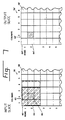
- Tomographic slice 56 consists of a plurality of voxel 58 arranged in a rectangular array of rows 60 and columns 62. Each voxel 58 is a digital value representing a brightness, or other characteristic, of its location in tomographic slice 56.
- the values of all voxels 58 within a window 64 are summed in a predetermined manner to derive an output value for a center voxel 66.
- the output value becomes the value of a voxel 58′ in an output tomographic slice 56′ having a position corresponding to the center voxel in window 64.
- window 64 is stepped a predetermined number of voxels 58 and the process is repeated to determine the output value for the center voxel then within window 64.
- window 64 is square with three voxels 58 on a side.
- the value of voxel 58′ in output tomographic slice 56′ in a position corresponding to voxel 58 in row 2 and column 2 of tomographic slice 56, is evaluated by summing the values of voxels 58 in rows 1-3 and columns 1-3. The sum is then normalized and the result is ascribed to the row-2 column-2 voxel 58′ in output tomographic slice 56′.
- window 64 is stepped one voxel 58 to right and the process is repeated to evaluate the output voxel 58′ at row 2, column 3.
- output tomographic slice 56′ contains the same number of voxels 58′, but with a spatial frequency reduced in accordance with the size of window 64 and the weighting applied to the values of surrounding voxels 58.
- linear weighting is employed. That is, the values of all nine voxels 58 in window 64 are summed and the result divided by 9 to produce the final value for the voxel 58 being calculated.
- Other window sizes and weighting functions could be applied and would have predictable effects on the spatial frequency of the result.
- the values of voxels 58 outside the central voxel 58 may be weighted with a Gaussian, exponential or triangular function depending upon its distance along a row or column from the central voxel 58.
- weighting may be applied according to the diagonal distance between voxels 58. As noted above, we have found the choice of a particular weighting function, as long as it approximates a low-pass filter, has little effect on the displayed 3D image.
- the spatial frequency of the filtered data is reduced by the amount determined by the filter response. If, for example, the original maximum spatial frequency was 10 KHz and the spatial frequency was reduced by a factor of two by the filter, the maximum spatial frequency in the filtered data is reduced to 5 KHz. Whereas the original sampling frequency to capture data up to 10 KHz is 20 KHz. For example, if it is desired to resample data originally sampled at twice the new sampling frequency, such resampling can be done by discarding every second data item, without destroying data in the result.
Landscapes
- Physics & Mathematics (AREA)
- Engineering & Computer Science (AREA)
- Computer Graphics (AREA)
- Geometry (AREA)
- Software Systems (AREA)
- General Physics & Mathematics (AREA)
- Theoretical Computer Science (AREA)
- Apparatus For Radiation Diagnosis (AREA)
- Image Processing (AREA)
- Magnetic Resonance Imaging Apparatus (AREA)
- Image Analysis (AREA)
- Analysing Materials By The Use Of Radiation (AREA)
- Image Generation (AREA)
Applications Claiming Priority (2)
| Application Number | Priority Date | Filing Date | Title |
|---|---|---|---|
| US07/118,628 US4831528A (en) | 1987-11-09 | 1987-11-09 | Apparatus and method for improvement of 3D images derived from tomographic data |
| US118628 | 1987-11-09 |
Publications (2)
| Publication Number | Publication Date |
|---|---|
| EP0316135A2 true EP0316135A2 (fr) | 1989-05-17 |
| EP0316135A3 EP0316135A3 (fr) | 1991-09-25 |
Family
ID=22379783
Family Applications (1)
| Application Number | Title | Priority Date | Filing Date |
|---|---|---|---|
| EP19880310480 Ceased EP0316135A3 (fr) | 1987-11-09 | 1988-11-08 | Production d'images à partir de données tomographiques |
Country Status (4)
| Country | Link |
|---|---|
| US (1) | US4831528A (fr) |
| EP (1) | EP0316135A3 (fr) |
| JP (1) | JPH01199279A (fr) |
| IL (1) | IL87511A (fr) |
Cited By (5)
| Publication number | Priority date | Publication date | Assignee | Title |
|---|---|---|---|---|
| EP0938063A3 (fr) * | 1998-02-18 | 2000-01-26 | Philips Patentverwaltung GmbH | Procédé d'imagerie bidimensionelle de structures pour le diagnostic médical |
| EP1026638A3 (fr) * | 1999-01-29 | 2002-05-15 | Mitsubishi Denki Kabushiki Kaisha | Méthode pour modeliser des objets graphiques représentés par des éléments de surface |
| EP1024457A3 (fr) * | 1999-01-29 | 2002-07-17 | Mitsubishi Denki Kabushiki Kaisha | Méthode pour rendu d'objets graphiques représentés par des éléments de surface |
| EP1024460A3 (fr) * | 1999-01-29 | 2003-07-02 | Mitsubishi Denki Kabushiki Kaisha | Objets graphiques représentés par des éléments de surface |
| EP1024436A3 (fr) * | 1999-01-29 | 2003-08-20 | Mitsubishi Denki Kabushiki Kaisha | Méthode de génération d'objets graphiques représentés par des éléments de surface |
Families Citing this family (38)
| Publication number | Priority date | Publication date | Assignee | Title |
|---|---|---|---|---|
| US5079699A (en) * | 1987-11-27 | 1992-01-07 | Picker International, Inc. | Quick three-dimensional display |
| US4953087A (en) * | 1988-10-24 | 1990-08-28 | General Electric Company | Three-dimensional images obtained from tomographic data having unequally spaced slices |
| US5257346A (en) * | 1990-09-24 | 1993-10-26 | International Business Machines Corporation | Wire-mesh generation from image data |
| US5357429A (en) * | 1992-04-02 | 1994-10-18 | Levy Richard A | Three-dimensional model generation using multiple angle tomographic scan planes |
| US5898793A (en) * | 1993-04-13 | 1999-04-27 | Karron; Daniel | System and method for surface rendering of internal structures within the interior of a solid object |
| US5396890A (en) * | 1993-09-30 | 1995-03-14 | Siemens Medical Systems, Inc. | Three-dimensional scan converter for ultrasound imaging |
| US5920319A (en) * | 1994-10-27 | 1999-07-06 | Wake Forest University | Automatic analysis in virtual endoscopy |
| US5782762A (en) * | 1994-10-27 | 1998-07-21 | Wake Forest University | Method and system for producing interactive, three-dimensional renderings of selected body organs having hollow lumens to enable simulated movement through the lumen |
| US6694163B1 (en) | 1994-10-27 | 2004-02-17 | Wake Forest University Health Sciences | Method and system for producing interactive, three-dimensional renderings of selected body organs having hollow lumens to enable simulated movement through the lumen |
| US5761333A (en) * | 1995-01-31 | 1998-06-02 | General Electric Company | Contrast enhancement for CT systems |
| DE19508823A1 (de) * | 1995-03-11 | 1996-09-12 | Philips Patentverwaltung | Verfahren zur Nachbildung der Oberfläche eines Objekts |
| US5594767A (en) * | 1995-11-02 | 1997-01-14 | General Electric Company | Methods and apparatus for enhancing image sharpness |
| US7486811B2 (en) * | 1996-09-16 | 2009-02-03 | The Research Foundation Of State University Of New York | System and method for performing a three-dimensional virtual examination of objects, such as internal organs |
| US7194117B2 (en) | 1999-06-29 | 2007-03-20 | The Research Foundation Of State University Of New York | System and method for performing a three-dimensional virtual examination of objects, such as internal organs |
| US6331116B1 (en) * | 1996-09-16 | 2001-12-18 | The Research Foundation Of State University Of New York | System and method for performing a three-dimensional virtual segmentation and examination |
| US6123733A (en) * | 1996-11-27 | 2000-09-26 | Voxel, Inc. | Method and apparatus for rapidly evaluating digital data processing parameters |
| US8682045B2 (en) * | 1997-02-25 | 2014-03-25 | Wake Forest University Health Sciences | Virtual endoscopy with improved image segmentation and lesion detection |
| US6246784B1 (en) | 1997-08-19 | 2001-06-12 | The United States Of America As Represented By The Department Of Health And Human Services | Method for segmenting medical images and detecting surface anomalies in anatomical structures |
| EP1133257A4 (fr) | 1998-11-25 | 2007-12-26 | Univ Wake Forest | Systeme ameliore d'endoscopie virtuelle a segmentation des images et detection des lesions |
| CN100352921C (zh) * | 1999-05-06 | 2007-12-05 | 威克福雷大学 | 用于鉴定引起免疫反应的抗原的组合物和方法 |
| DE19922975A1 (de) * | 1999-05-19 | 2000-11-23 | Star Division Corp | Verfahren und Vorrichtung zur Erzeugung einer 3D-Darstellung aus einem 2D-Bild |
| US6625565B1 (en) * | 2000-06-01 | 2003-09-23 | Lockheed Martin Corporation | Method and apparatus for determining an unsupervised planar geodesic path |
| WO2001093745A2 (fr) * | 2000-06-06 | 2001-12-13 | The Research Foundation Of State University Of New York | Plan de traitement et visualisation assistes par ordinateur faisant appel au calage et a la fusion d'images |
| WO2002029723A1 (fr) | 2000-10-02 | 2002-04-11 | The Research Foundation Of State University Of Newyork | Navigation et examen virtuels ameliores |
| US7630750B2 (en) * | 2001-02-05 | 2009-12-08 | The Research Foundation For The State University Of New York | Computer aided treatment planning |
| US20020164061A1 (en) * | 2001-05-04 | 2002-11-07 | Paik David S. | Method for detecting shapes in medical images |
| US7324104B1 (en) | 2001-09-14 | 2008-01-29 | The Research Foundation Of State University Of New York | Method of centerline generation in virtual objects |
| US7596256B1 (en) | 2001-09-14 | 2009-09-29 | The Research Foundation For The State University Of New York | Computer assisted detection of lesions in volumetric medical images |
| US7260250B2 (en) * | 2002-09-30 | 2007-08-21 | The United States Of America As Represented By The Secretary Of The Department Of Health And Human Services | Computer-aided classification of anomalies in anatomical structures |
| US20100260390A1 (en) * | 2005-11-30 | 2010-10-14 | The Research Foundation Of State University Of New York | System and method for reduction of false positives during computer aided polyp detection |
| US8452061B2 (en) * | 2005-11-30 | 2013-05-28 | The Research Foundation Of State University Of New York | Electronic colon cleansing method for virtual colonoscopy |
| US8422767B2 (en) * | 2007-04-23 | 2013-04-16 | Gabor Ligeti | Method and apparatus for transforming signal data |
| US8243334B2 (en) | 2008-06-06 | 2012-08-14 | Virginia Venture Industries, Llc | Methods and apparatuses for printing three dimensional images |
| DE102009011382A1 (de) * | 2009-03-05 | 2010-09-09 | Rheinisch-Westfälische Technische Hochschule Aachen | Verfahren und Vorrichtung zur Quantifizierung der Bildgüte und zur bewegungssynchronen Erfassung einer tomografischen Schnittaufnahme eines Objektes |
| JP2012120057A (ja) * | 2010-12-02 | 2012-06-21 | Sony Corp | 画像処理装置、および画像処理方法、並びにプログラム |
| US9646411B2 (en) * | 2015-04-02 | 2017-05-09 | Hedronx Inc. | Virtual three-dimensional model generation based on virtual hexahedron models |
| WO2018064248A1 (fr) | 2016-09-30 | 2018-04-05 | University Hospitals Cleveland Medical Center | Appareil et procédé de construction d'un modèle 3d virtuel à partir d'une vidéo ultrasonore 2d |
| USD912638S1 (en) * | 2019-03-06 | 2021-03-09 | Shenzhen Radiant Technology Co., Ltd | Display screen |
Family Cites Families (9)
| Publication number | Priority date | Publication date | Assignee | Title |
|---|---|---|---|---|
| US4002911A (en) * | 1974-05-20 | 1977-01-11 | Emi Limited | Data acquisition in tomography |
| US4694404A (en) * | 1984-01-12 | 1987-09-15 | Key Bank N.A. | High-speed image generation of complex solid objects using octree encoding |
| JPH0746391B2 (ja) * | 1984-09-14 | 1995-05-17 | 株式会社日立製作所 | 図形シエ−デイング装置 |
| GB8518803D0 (en) * | 1985-07-25 | 1985-08-29 | Rca Corp | Locating target patterns within images |
| US4737921A (en) * | 1985-06-03 | 1988-04-12 | Dynamic Digital Displays, Inc. | Three dimensional medical image display system |
| US4710876A (en) * | 1985-06-05 | 1987-12-01 | General Electric Company | System and method for the display of surface structures contained within the interior region of a solid body |
| DE3650169T2 (de) * | 1985-06-05 | 1995-08-03 | Gen Electric | Anlage und Verfahren zur Anzeige von im Inneren eines Festkörpers eingeschlossenen Oberflächenstrukturen. |
| US4697594A (en) * | 1985-08-21 | 1987-10-06 | North American Philips Corporation | Displaying a single parameter image |
| US4719585A (en) * | 1985-08-28 | 1988-01-12 | General Electric Company | Dividing cubes system and method for the display of surface structures contained within the interior region of a solid body |
-
1987
- 1987-11-09 US US07/118,628 patent/US4831528A/en not_active Expired - Fee Related
-
1988
- 1988-08-22 IL IL87511A patent/IL87511A/xx not_active IP Right Cessation
- 1988-11-07 JP JP63279551A patent/JPH01199279A/ja active Pending
- 1988-11-08 EP EP19880310480 patent/EP0316135A3/fr not_active Ceased
Cited By (5)
| Publication number | Priority date | Publication date | Assignee | Title |
|---|---|---|---|---|
| EP0938063A3 (fr) * | 1998-02-18 | 2000-01-26 | Philips Patentverwaltung GmbH | Procédé d'imagerie bidimensionelle de structures pour le diagnostic médical |
| EP1026638A3 (fr) * | 1999-01-29 | 2002-05-15 | Mitsubishi Denki Kabushiki Kaisha | Méthode pour modeliser des objets graphiques représentés par des éléments de surface |
| EP1024457A3 (fr) * | 1999-01-29 | 2002-07-17 | Mitsubishi Denki Kabushiki Kaisha | Méthode pour rendu d'objets graphiques représentés par des éléments de surface |
| EP1024460A3 (fr) * | 1999-01-29 | 2003-07-02 | Mitsubishi Denki Kabushiki Kaisha | Objets graphiques représentés par des éléments de surface |
| EP1024436A3 (fr) * | 1999-01-29 | 2003-08-20 | Mitsubishi Denki Kabushiki Kaisha | Méthode de génération d'objets graphiques représentés par des éléments de surface |
Also Published As
| Publication number | Publication date |
|---|---|
| IL87511A (en) | 1992-03-29 |
| JPH01199279A (ja) | 1989-08-10 |
| EP0316135A3 (fr) | 1991-09-25 |
| IL87511A0 (en) | 1989-01-31 |
| US4831528A (en) | 1989-05-16 |
Similar Documents
| Publication | Publication Date | Title |
|---|---|---|
| US4831528A (en) | Apparatus and method for improvement of 3D images derived from tomographic data | |
| US4989142A (en) | Three-dimensional images obtained from tomographic slices with gantry tilt | |
| US4914589A (en) | Three-dimensional images obtained from tomographic data using a variable threshold | |
| EP0412748B1 (fr) | Méthodes et appareils pour générer des images tridimensionnelles | |
| EP0365141B1 (fr) | Système et méthode d'affichage de plans de coupes obliques dans la région intérieure d'un objet solide | |
| EP0318176B1 (fr) | Appareil et méthodes de traitement d'images | |
| EP0968683B1 (fr) | Procede et appareil de formation et d'affichage d'une image a partir d'une pluralite d'images partielles | |
| JP2744490B2 (ja) | 物体内部構造表面の2次元像を表示する装置と方法 | |
| US4737921A (en) | Three dimensional medical image display system | |
| US5170347A (en) | System to reformat images for three-dimensional display using unique spatial encoding and non-planar bisectioning | |
| US6175655B1 (en) | Medical imaging system for displaying, manipulating and analyzing three-dimensional images | |
| US4729098A (en) | System and method employing nonlinear interpolation for the display of surface structures contained within the interior region of a solid body | |
| CA1315902C (fr) | Minimisation de points diriges generes par la methode des cubes diviseurs tridimensionnels | |
| US4953087A (en) | Three-dimensional images obtained from tomographic data having unequally spaced slices | |
| EP0204225B1 (fr) | Dispositif et procédé pour la visualisation de structures de surface contenues dans la région intérieure d'un corps solide | |
| Goldwasser et al. | Real-time display and manipulation of 3-D medical objects: The voxel processor architecture | |
| GB2190570A (en) | Method and apparatus for imaging volume data | |
| EP0318293B1 (fr) | Dispositif et procédé de traitement de données tomographiques | |
| WO1997009690A1 (fr) | Criblage dimensionnel de donnees et connectivite floue pour analyse d'image d'irm | |
| EP0373854B1 (fr) | Système et méthode pour la détection de structures internes contenues à l'intérieur d'un objet solide | |
| EP0318291B1 (fr) | Dispositif et méthode pour la génération d'images à partir de données tomographiques | |
| US5736857A (en) | Method and apparatus for realistic presentation of interpolated magnetic resonance images | |
| JPH0675576B2 (ja) | 超音波画像表示装置 |
Legal Events
| Date | Code | Title | Description |
|---|---|---|---|
| PUAI | Public reference made under article 153(3) epc to a published international application that has entered the european phase |
Free format text: ORIGINAL CODE: 0009012 |
|
| AK | Designated contracting states |
Kind code of ref document: A2 Designated state(s): DE FR GB NL |
|
| PUAL | Search report despatched |
Free format text: ORIGINAL CODE: 0009013 |
|
| AK | Designated contracting states |
Kind code of ref document: A3 Designated state(s): DE FR GB NL |
|
| 17P | Request for examination filed |
Effective date: 19911220 |
|
| 17Q | First examination report despatched |
Effective date: 19930524 |
|
| STAA | Information on the status of an ep patent application or granted ep patent |
Free format text: STATUS: THE APPLICATION HAS BEEN REFUSED |
|
| 18R | Application refused |
Effective date: 19960908 |