EP0316148A2 - Rechner für ein Radarsystem - Google Patents
Rechner für ein Radarsystem Download PDFInfo
- Publication number
- EP0316148A2 EP0316148A2 EP88310535A EP88310535A EP0316148A2 EP 0316148 A2 EP0316148 A2 EP 0316148A2 EP 88310535 A EP88310535 A EP 88310535A EP 88310535 A EP88310535 A EP 88310535A EP 0316148 A2 EP0316148 A2 EP 0316148A2
- Authority
- EP
- European Patent Office
- Prior art keywords
- data
- processor
- samples
- range
- azimuth
- Prior art date
- Legal status (The legal status is an assumption and is not a legal conclusion. Google has not performed a legal analysis and makes no representation as to the accuracy of the status listed.)
- Withdrawn
Links
Images






Classifications
-
- G—PHYSICS
- G01—MEASURING; TESTING
- G01S—RADIO DIRECTION-FINDING; RADIO NAVIGATION; DETERMINING DISTANCE OR VELOCITY BY USE OF RADIO WAVES; LOCATING OR PRESENCE-DETECTING BY USE OF THE REFLECTION OR RERADIATION OF RADIO WAVES; ANALOGOUS ARRANGEMENTS USING OTHER WAVES
- G01S13/00—Systems using the reflection or reradiation of radio waves, e.g. radar systems; Analogous systems using reflection or reradiation of waves whose nature or wavelength is irrelevant or unspecified
- G01S13/88—Radar or analogous systems specially adapted for specific applications
- G01S13/89—Radar or analogous systems specially adapted for specific applications for mapping or imaging
- G01S13/90—Radar or analogous systems specially adapted for specific applications for mapping or imaging using synthetic aperture techniques, e.g. synthetic aperture radar [SAR] techniques
- G01S13/9004—SAR image acquisition techniques
- G01S13/9011—SAR image acquisition techniques with frequency domain processing of the SAR signals in azimuth
Definitions
- This invention relates to a processor for a radar system, for a synthetic aperture radar (SAR) system.
- SAR synthetic aperture radar
- Synthetic aperture radar is a known technique which is suitable for producing a high resolution radar image of a terrain under a moving radar platform, e.g.an aircraft or satellite.
- a typical synthetic aperture radar system will now be described with reference to Figures 1 and 2 of the accompanying drawings.
- the system comprises a radar carried on a moving platform 1, which looks approximately sideways to the path of motion 3 of the platform 1. As the platform moves along the path 3, the radar periodically transmits radar pulses and collects the echoes. A pulse illuminates an area 5 of the terrain beneath the platform, which is commonly referred to as the radar footprint. The collected radar echoes are processed by the radar system to produce the required radar image.
- the footprint moves along a strip 7 of the terrain referred to as the illuminated swath, the direction along the length of the swath being referred to as the azimuth direction and the direction across the width of the swath being referred to as the range direction.
- Radar echoes are received in the time between successive radar pulses, as shown in Figure 2, in a data reception window 11, and the echo signal is sampled (range line).
- the resolution of the image obtained in the range direction is primarily determined by the bandwidth of the transmitted pulse, a high resolution being obtained with a high bandwidth pulse using known range processing algorithms, which correlate the range lines with a replica of the transmitted pulse signal.
- High resolution can be obtained in the azimuth direction by choosing the pulse repetition interval such that successive footprints overlap.
- the range line signals obtained from each set of overlapping footprints are processed simultaneously (being correlated or combined in another suitable relation with data relating to the Doppler shift of the echo signals) and in this way, an azimuth resolution comparable to that obtainable with an antenna of much larger size and aperture is obtained.
- a problem with such azimuth processing is the so-called range migration effect under which the distance between the platform and a point on the terrain illuminated by the beam changes from pulse to pulse. Consequently any such point is represented by range line samples at different positions on successive range lines, the positions defining a range migration path, which may be curved, or substantially linear. Since the correlation with the Doppler cofficients has to be carried out on data samples on the range migration paths, the range migration effect must be taken into account to perform the processing.
- U.S. Patent No. 4132989 is a proposal for range migration correction in azimuth processing, which entails the use of a number of shift registers, one for each sample range line, connected in cascade. Range migration correction is performed by applying a variable delay to the output of each shift register. The delayed outputs (corresponding to the same point on the ground) are then correlated with the Doppler reference coefficients.
- the invention provides an azimuth processor for a synthetic aperture radar system, which comprises a sequence of data storage locations, and means for entering successive range line samples derived from successive radar echo signals into the sequence of storage locations, at a variable starting location along the sequence.
- the starting location at which successive range line samples are entered can be changed so that the discontinuities in the saw-tooth form of data will be transparent to the processor, enabling the processing advantages of this form of data to be achieved.
- the range line samples entered into the sequence of storage locations may be samples of radar return samples after range processing eg. by correlation with a replica of the transmitted pulse.
- columns of data are derived from the data successively fed into the input sequence of data storage locations,
- the data may be transferred from the input sequence to a two-dimensional array of storage locations, and samples may be read from the array for azimuth processing.
- the array may be divided into modules.
- the relative lengths of rows and columns in the array may be variable, in order to trade the length of the swath being measured against the azimuth resolution provided within that swath.
- the two dimensional array may be formed by a data memory which could also include the input row and/or an output row.
- the processor may include a linear range migration interpolator for performing a co-ordinate transformation to interpolate samples on a co-ordinate axis system in which one axis is skew compared to the azimuth direction.
- a co-ordinate transformation enable azimuth processing to be carried out along columns in the two-dimensional array where the range migration is linear (and indeed even the co-ordinate transformation would be unnecessary if there was no range migration).
- the range migration path also has a non-linear component azimuth processing can take place along range migration curves by use of a further range migration processor of the form described and claimed in our co-pending application No. 88 19529.
- the curvature can be approximated to a series of linear sections, and azimuth processing can be carried out on samples interpolated by the linear range migration interpolator on skew axes parallel to each linear section. The results can be combined to yield azimuth processed samples.
- the sequence of data storage locations may be arranged in the form of a closed loop, in that the entire sequence will be filled and in the same order, irrespective of the starting position.
- the storage locations at the start of the row are filled in succession.
- the storage locations are configured as a plurality of groups, and successive range line samples are fed in use to a location in each group in turn. This gives processing advantages, because when columns of data derived from the data successively fed into the groups are azimuth processed, columns of data derived from the different groups will require the same reference coefficients at any given time for azimuth processing. This enables the necessary reference coefficients to be stored in a single memory.
- An output row of storage locations for processed data may be provided, which can be read from a variable starting point along the row which may move in step with that for the input row: this provides output data in the same structure as the input data.
- the input row could be part of an input buffer, which could consist only of that row, or could consist of more than one row.
- the output row of storage locations could be part of an output buffer, which could consist only of that row, or could consist of more than one row.
- sequence of storage locations may be formed by a shift register.
- the invention also provides an azimuth processor for a synthetic aperture radar system, comprising means for performing a co-ordinate transformation on range line samples derived from successive radar echo signals, so that samples are interpolated on a skew axis parallel to a straight line approximation of the range migration curve, and means for azimuth processing such data wherein the skew axis is of saw-tooth form.
- the invention also provides a processor for two-dimensional separable convolution/correlation of an array of samples, comprising a correlator or convolver to correlate or convolve each line of input samples from the array, a sequence of data storage locations for storing the correlated or convolved lines of samples, a two-dimensional array of storage locations arranged to receive successive rows of samples from the data storage locations, and correlators or convolvers arranged to correlate or convolve the samples in the columns in the array .
- the SAR processing is carried out in two stages, namely, range processing 13 and azimuth processing 15, shown in Figure 3, but the azimuth processing may be performed first if desired.
- Range processing can be implemented using the correlator architecture described in the accompanying patent application No. 88 02904 (I/7555/MRC).
- the processing can be carried out at high speed. preferably real time, permitting incorporation on the moving radar platform.
- each radar echo signal (possibly range processed) is available to the azimuth processor as a sequence of data samples, referred to as a range line.
- the data samples in range lines are considered to be complex-valued, comprising real and imaginary components.
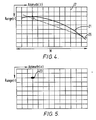
- Azimuth processing for point P is basically a correlation of the signal along the trajectory 21 with the appropriate reference sequence. The effect of this correlation is to compress the spread of the target energy along the trajectory 21 into a relatively small area 23. This operation is repeated for every point of the two-dimensional grid of Figure 4. This is known as azimuth processing and yields a SAR image with a high resolution in the azimuth dimension.
- the curvature of the range migration trajectory 21 of Figure 4 is negligibly small.
- the range migration trajectory can be represented as the straight line 25 in Figure 4.
- azimuth correlation can be carried along lines parallel to each of these linear sections separately and the results of these correlations can be added with appropriate delays between them, to give the complete azimuth processed SAR image.
- Separate azimuth processors may be provided, one for each linear section direction, or the same processor may be used for each direction in succession.
- the basic requirement of the azimuth processor is to correlate signal values in a linear trajectory 25 with a reference sequence and to repeat this for every point in the two-dimensional grid.
- SAR azimuth processing is carried out using an algorithm which involves interpolating to obtain data samples along range migration lines 25 and then correlating the data in these lines with appropriate reference sequences.
- the SAR azimuth processor 27 of Figure 6 consists of a linear range migration processor 29 and an azimuth correlation processor 31.
- the linear range migration processor 29 consists of an interpolator.
- the function of the linear range migration processor 29 is now described with references to Figures 7 and 8.
- the sampled range line data is available on a range (r) - azimuth (z) grid, as shown in Figure 7a.
- the azimuth correlation processor 31 has to carry out azimuth correlations along linear range migration lines 25.
- the axis y shown in Figure 7b, is defined as a co-ordinate axis parallel range migration line 25 of Figure 4.
- the function of the linear range migration processor is to transform data samples located on a r-z grid into data samples located on a r-y grid. This is done to allow the azimuth correlation processor 31 to correlate data along lines parallel to the y-axis. This is achieved by interpolations along range lines i.e. obtaining data samples for points Q1,Q2,Q3 etc. from data at points P1,P2,P3 etc.
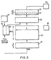
- FIG. 9 A functional block diagram of the azimuth correlation processor 31 is shown in Figure 9.
- This processor consists of an input buffer 51, a data memory 53, a data processor 55, an output buffer (57,59), coefficient memory (61,63), an output interpolater 65, an auxiliary processor 67 and a system controller 69.
- Data from the linear range migration processor are entered in range line order into the input buffer 51. This data then gets transferred to the data memory 53.
- the data processor 55 processes the data in the data memory 53 using the coefficients in the coefficient memory (61,63) and stores the results in the output buffer (57,59).
- the processed data is extracted from the output buffer (57,59) in range line order and then interpolated using the interpolator 65 and presented at the output.
- the auxiliary processor 67 generates the coefficients required for data processing using algorithms.
- the complete system is controlled by the controller 69.
- Data is processed in the azimuth correlation process in blocks of K range lines.
- the input buffer 51 can hold K range lines, each of length R.
- the data memory can hold (M + K) range lines, where M is the azimuth correlation length, i.e. M is the number of echoes over which the azimuth correlation must be carried out in order to achieve the required azimuth resolution.
- the output buffer consists of two parts 57 and 59, each capable of holding K azimuth processed range lines. As examples of suitable values, R could be 5000, M could be 1000, while K could be 64.
- the input buffer 51, the data memory 53 and the output buffer are all two-dimensional in structure.
- the length of all these storage units in the horizontal direction of Figure 9 is R storage locations, where R is the length of a range line. Range lines are written along horizontal lines in these units.
- the heights of the input buffer 51, data memory 53 and the output buffer (57,59) are K, M + K and 2K storage locations respectively. Each storage location can hold one complex sample.
- the size of a storage location in the output buffer (57,59) may be different, usually larger, because this is used to store processed data.
- An azimuth processing cycle is the period taken for the azimuth correlation processor to azimuth process K range lines.
- This azimuth processed data is stored in the part 57 of the output buffer connected to the data processor 55.
- K new range lines are entered into the input buffer 51 of the processor and the K range lines processed during the preceding azimuth processing cycle are extracted from the part 59 of the output buffer connected to the output.
- the K new range lines in the input buffer 51 are transferred vertically i.e. without any horizontal displacement, to the data memory 53 to overwrite the oldest K range lines.
- the K newly processed range lines are transferred from part 57 to part 59 of the output buffer.
- the same effect could be achieved by interchanging the roles of the two parts 57 and 59 of the output buffer for the next azimuth processing cycle, i.e. by connecting part 57 to the output and part 59 to the data processor 55.
- the same idea could be used to avoid the data transfer time between the input buffer and the data memory, by designing the input buffer as a part of the data memory. Then the size of the data memory would be M + 2K range lines, each of length R. A section of this, of size (KxR), would be operating as the input buffer 51 and the other section of size (K + M) x R would be operating as the data memory 53, in any given azimuth processing cycle. This input buffer section would be taken as a part of the data memory for the next azimuth processing cycle.
- the input buffer 51 can be regarded as the curved surface of a cylinder of circumference R and height K, with the axis in the vertical direction of figure 9.
- the rectangular input buffer shown in figure 9 can be made to operate as such a cylindrical input buffer by evaluating the horizontal address modulo R. Range lines are wrapped around this cylindrical buffer beginning from a location indicated by a pointer WR, i.e. successive samples of a range line are stored in successive locations in a horizontal line of the cylindrical memory beginning from the location indicated by WR.
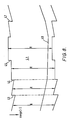
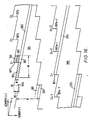
- Figure 10a shows the functional block diagrams of the processor and 10b a typical saw-tooth edged data structure 91 which is entered into the processor.
- the function of the data processor is to correlate a data sequence of length M + K samples, held in a vertical line 85 in the data memory 53 with an appropriate reference sequence of length M from the coefficient memory 61 to generate K correlated outputs and then store these K outputs along the same vertical line 87 of the output buffer part 57in line 87. This is carried out for all R vertical lines of the data memory 53. Some of these operations may be carried out in parallel.
- the line segment 103 (2) would be staggered by a distance d1 with respect to the line segment 103 (1) and 103 (3) would be staggered by a distance d2 with respect to 103 (2) .
- the data processor would be unable to process data by correlating along vertical lines of the data memory 53, after passing a discontinuity 93 in the input data structure.
- the range lines are entered at a variable starting point at the input buffer 51, excess samples after the row is filled being entered at the start of the row thereafter.
- the input buffer 51 is a two-dimensional memory of width R and height K. Range lines are written horizontally in this buffer, e.g. line 81.
- This buffer can be regarded as a circular buffer, or as a surface of a cylinder with a vertical axis, of height K and circumference R.
- the rectangular buffer 51 is made to appear as a circular buffer by evaluating the horizontal address modulo R.
- Range lines 81 are wrapped around this circular buffer, beginning from a location indicated by the pointer WR. These may be wrapped in either direction. However, once a direction has been chosen at the beginning of the SAR processing operation, this direction has to be maintained throughout the operation. For convenience of explanation it is taken that range lines are written from left to right beginning from WR, in the input buffer 51 shown in Figure 10. Range line data will then be available in this direction in the data memory and the output buffer.
- the pointer WR which indicates the start location for a range line 81 may be placed at an arbitrary position at the beginning of the SAR processing operation. Following this, it is moved at every discontinuity in the input data structure, as described below. The point WR is held stationary between discontinuities.
- the data processor Since the correlation length is M, the data processor will be unable to provide a valid image sample for line 105 until M samples of these lines are collected along the vertical line 85 of the data memory. It must be noted that this is a physical limitation of the SAR Processing operation and not a limitation of the processor.
- the azimuth distance between discontinuities is not limited in any way by the azimuth correlation processor described here. It depends on the organisation of the input data structure by the user of the processor. If the slope of the linear range migration is relatively large these discontinuities may have to be placed close to each other to avoid relatively large unprocessed areas in the image. Alternatively, if the slope of the range migration line is changing relatively rapidly with azimuth variable z, these discontinuities may have to be placed relatively close to each other to ensure smooth transition at discontinuities. Although Figure 8 may give the impression that the slope of linear range migration varies rapidly, in practice these changes occur at a relatively slow rate.
- the output buffer shown in Figures 9 and 10 consists of two parts 57 and 59. Each of these parts is two-dimensional in structure and of size (KxR), i.e. it consists of K horizontal lines with each line capable of holding one azimuth processed range line of data. One of these two parts 59 is connected to the output whilst the other part 57 is connected to the data processor 57. In any azimuth processing cycle K range lines of processed data is written into 57 whilst the K lines processed in the preceding azimuth processing cycle are extracted, in range line order, from 59. At the end of this azimuth processing cycle, the contents of 57 are transferred to 59. This may equivalently and more quickly be achieved by swapping the roles of the two parts 57 and 59 of the output buffer, i.e. connecting 59 to the data processor and 57 to the output bus for the next azimuth processing cycle.
- KxR two-dimensional in structure and of size
- the part 59 of the output buffer is a circular buffer of height K and circumference R. Range lines of data are available in this buffer wrapped around it horizontally beginning from a location indicated by the pointer RE.
- the direction, i.e. right to left or left to right, in which range line data is available in the output buffer, is the same as the direction in which data was written in the input buffer.
- a vertical line 87 of storage locations in the output buffer receives processed data corresponding to line 103 in the input data structure.
- the pointer RE has to be moved left by d1 locations after passing the discontinuity 93. Similarly, after passing 95 it is moved by d2 locations to the left. If the discontinuity is in the opposite direction, e.g. 47 of Figure 8, the pointer RE is moved to the right, the amount of movement being equal to the size of the discontinuity.
- the value of the pointer RE is evaluated modulo R because the output buffer is circular.
- the pointer RE must be initialised to the same value as WR at the beginning of the SAR Processing operation. Following this, the pointer RE is moved by the same distance and in the same direction as WR at discontinuities in the input data structure. However, since there is a latency in the azimuth correlation processor described here the pointer RE is moved a short time after the corresponding movement in WR.
- the processed SAR image is read from the output buffer 59 in range line order, If the output is to have the same structure as the input, i.e. that indicated in Figures 8 and 10, the range lines must be read beginning from the location of the pointer RE and in the direction in which range lines have been stored in the input buffer. However, if a different structure is required for the output, e.g.if only a part of the image is required a different method can be adopted for extracting data from the output buffer. In any case the horizontal address for reading range line data must be evaluated modulo R. This is because the buffer 59 is circular.
- the processed SAR data obtained from the output buffer 59 will be on the r-y grid shown in Figure 7. It is usually desirable to present this data to the user in the original range (r) - azimuth (z) grid shown in the same figure.
- the data was converted from the r-z grid to the r-y grid in the linear range migration processor 29 solely to simplify processing in the azimuth correlation processor 31.
- the function of the interpolator 65 in Figure 9 is to carry out the r-y to r-z co-ordinate transformation, which is the inverse of the operation implemented in the linear range migration processor 29. Referring to Figure 7, it can be seen that this co-ordinate transformation involved interpolating the values of a range line at points P1,P2,P3,P4 etc.
- this interpolation can be carried out on-the-fly in the interpolator 65.
- the SAR image is available in a range (r) - azimuth (z) grid.
- This interpolator 65 can also be made to carry out other resampling operations such as slant-range to ground-range conversion.
- the function of the data processor 55 in the azimuth correlation processor is to correlate the data contained in vertical lines of storage locations of the data memory 53 with the sequences of coefficients held within the coefficient memory (61,63). This correlation can be carried out using a variety of techniques.
- the data processor 55 can implement the correlation using time domain or frequency domain techniques.
- a suitable technique for correlation in the time domain is described in our co-pending application no. I/7559/MRC.
- the known frequency domain techniques make use of known transforms such as Fourier and number theoretic transforms, and fast algorithms for evaluating these transforms such as the known fast Fourier transform (FFT) algorithm. If the FFT algorithm is used to carry out the correlation, the data processor 55 will consist of FFT butterfly processors.
- the coefficient memory (61,63) of Figure 9 contains the reference sequences of length M, required for azimuth correlation.
- the coefficients of these sequences are generated by the auxiliary processor. Since these coefficients must be updated fairly frequently the coefficient memory is designed in two parts 61 and 63. One of these parts 61 is connected to the data processor and the others to the auxiliary processor. This enables the auxiliary processor 67 to load a new set of coefficients whilst the data processor is processing the SAR data with the old set of coefficients. After the loading of a new set of coefficients has been completed and when it is required to use the new set of coefficients is is possible either to transfer the coefficients from part 63 to part 61 or to swap the roles or the parts 61 and 63, i.e.
- the processor shown in Figure 9 may be partitioned as shown in Figure 11, into B modules 1111,1112,..., 111 B .
- B could be 10.
- Each of these modules 111 is referred to as an azimuth processing module (APM).
- the input buffer 51 data memory 53 and the output buffer (57,59) are partitioned into identical and non-overlapping sections 113, 115 and (119,121) respectively each of width N. These buffers are partitioned primarily for implementation purposes. The structure of these buffers and memories 51,53 and (57,59) and their operation have been described earlier.
- each data processing section 117 i has to process the N data sequences contained in the N vertical columns of the data memory section 115 i , generating K processed samples for each of these N sequences in the time taken to enter K new range lines into the input buffer 51.
- the storage units which form the input buffer 113 i , the data memory 115 i and the output buffer sections 119 i and 121 i have two data ports, one for writing data and the other for reading data.
- the APM design can be modified to make use of single-port memory units using tristate drivers, as illustrated in Figure 12.
- a tri-state driver can be controlled either to electrically connect its input to its output or to electrically isolate its output from its iput. For example, when the azimuth data processor section 117 is processing data in the memory section 115, the tri-state driver 1292 will be controlled such that its output is isolated from its input. All the B APMs can be controlled by a central controller or some local control facilities 127 can be provided for each APM.
- each module can generate a portion of the SAR image in real time, it can be tested under real operating conditions before assembling the modules to form the complete SAR processor. Since the modules can be identical in structure, a module can be tested by comparing its output with that of another receiving the same input data. By providing a redundant APM, each APM can periodically be taken out of service without interrupting the SAR processing operation. This periodic testing of APMS can be carried out automatically by introducing built-in self-test features into each module.
- any APM can replace another. Since the APMs operate independently, this replacement APM need not be physically adjacent to the APM being replaced. Hence if tests reveal a fault in an APM, the faulty APM can be replaced by a redundant APM. The whole test and replace procedure can be automated. Such a system will be capable of reconfiguring itself for fault-free operation while in operation. This feature makes the processor particularly attractive for on-board SAR processing.
- Another advantage is graceful degradation. Since an APM generates a band of the image a fault in this APM and does not lead to the corruption of the complete image. Since there is a one-to-one correspondence between a band of the image and the APM generating this band, the identification of a faulty band of the image will also indicate the faulty APM, thereby simplifying the fault diagnosis problem.
- This architecture is also relatively less sensitive to design timing errors. If an APM fails to operate at the designed clock frequency f c , the effect of this is to reduce the number N of vertical lines of data that can be processed by this module. This gets reflected as a reduction in the width of the swath that can be processed in real time. In such an event an additional APM can be inserted to process the complete specified swath.
- the processor architecture consists of an array of APMs
- the swath-width, resolution or the throughput can be increased by increasing the number of APMs in the system.
- the azimuth resolution can be improved by reducing the swath width and vice versa, without any change in the throughput.
- the throughput of the fixed hardware design can be increased either by reducing the swath-width or the azimuth resolution.
- range lines are written by write address pointer WR into input buffers 51, 113 arranged in continuous form, in that the pointer fills up successive storage locations along an input row to the end of the row, and then fills up storage locations from the start of that row.
- the number of storage locations is equal to the number of range lines samples so that a fresh line starts to be written in when the pointer returns to its starting position.
- the data written in is advanced column-wise in the buffer 51, 113 before it is over-written by the next line, or the pointer WR is advanced column wise to the next row.
- the range line samples are entered into the data storage locations in a different sequence.
- This new sequence can perhaps best be explained by considering a simple example of how data could be fed in, in the Figure 11 embodiment as already described.
- the pointer WR has moved to the first storage location of input buffer module 113 1.
- the data is then entered into the second, third etc. storage locations and progressively fills up the first row of module 113 1, continues at the first storage location of the module 1132, progressively fills up the first row of that module, continues at the first storage location of the first row of module 113 3, and so on until the whole range line has been entered.
- the input row is continuous in that the pointer returns to the starting position for the next range line (the first location of module 1131 ), the line written in being advanced column- wise before it is over-written.
- the pointer steps to a different starting position.
- the first sample of the data line is entered in the first storage location of the first fow of input buffer module 1131
- the second sample is entered in first storage location of the first row of the second input buffer module 1132
- the third sample is entered into the first storage location of the first row of the third input buffer module 1133 .
- the Bth sample is entered into the first storage location of the first row of the Bth input buffer module.
- the next sample is entered into the second storage location of the first row the first buffer module, the next into the second storage location of the first row of the second buffer module, the 2 Bth sample into the second storage location of the first row of the Bth module, the (2 B+1)th sample in the third location of the first row of the first module, and so on.
- the last B samples of a range line are entered in the last locations of the first row of each of the buffer modules 113 in turn, and the first B samples of the next range line are entered into the first locations of the first rows of the buffer modules in turn as before, the last input data being transferred column-wise before it is over-written (or the write address pointer can be advanced columnwise to the next row, and the first B samples of the next range line can be entered in the equivalent locations in the next row).
- the input sequence is again in continuous form in that the number of storage locations is equal to the number of range lines samples, and the same pattern of entry is repeated.
- the pointer WR steps the appropriate number of positions along the sequence of storage locations i.e. the order in which they are filled.
- the columns of data in each module 115 are combined, for example correlated, with sequences of reference coefficients in a coefficient memory (not shown).
- a coefficient memory (not shown).
- the first data memory module 1151 which since range lines may comprise 5000 samples and there may be 10 modules, may contain 500 columns of data, those columns are fed sequentially, one column at a time, to the processor (eg starting at the left-hand side of the modules and working to the right-hand side) together with the appropriate columns of reference coefficients.
- the same procedure happens at the other modules.
- the values of the columns of reference coefficients depends on the range of the respective sample. 100 columns of reference coefficients may be used across the full length of a range line i.e. the same coefficient column may be used for 50 data columns in data memory 115.
- the first 50 columns of the first data memory module 115 requires the same column of reference coefficients, and a second column of reference coefficients is required for the next 50 columns of data.
- all the modules require different coeffficients for the first 50 columns, and similarly different coefficients for the second 50 columns i.e. at any given time the modules are using different reference coefficients.
- the columns represent data on range migration lines which actually traverse across the length of the range lines (and of the imaged swath)
- different sets of 10 reference coefficient columns are needed for different parts of these range migration lines. Consequently, each module 117 needs access to the full range of, in this case 100 columns of reference coefficients. It is therefore necessary for each module to have an individual coefficient memory containing a 100 columns of reference coefficients to be attached to it.
- the data columns are again fed sequentially out of the respective data memory modules 115 and correlated with appropriate reference columns from the reference coefficient column memory.
- the first data line from each module 115 represents closely spaced positions along the range line and hence require the same reference coefficient column.
- This same coefficient is in fact used for all the first 5 lines which are sequentially transferred from each data memory module 115 to the respective processing module 117.
- the next reference coefficient column is then used for all the next 5 lines sequentially transferred from each memory module 115 to the processing module 117. At any given time, all the modules require the same reference coefficient column.
- reference coefficient memory is now separate from the processing module it is easier to change it eg if it is desired to correlate over a different column length M. Equally, if desired it is now possible to have more sets of coefficients across the line of range line samples eg a different set of coefficients could be used for each column of data in the memory modules.
- the write address pointer will move along the pattern when there is a discontinuity in a range line eg if the discontinuity corresponds to 10 samples, the write address pointer would move from position 1 to position 11 which in the example described above would mean moving from the first space in the first module to the second space in the first module.
- a discontinuity of 12 samples would mean moving to position 13 i.e. the second space of the third module.
- the sequence in which the input data is fed to the input row of the modules may be varied if desired. Some benefit may be gained if the pattern departs from that described. The pattern must, however, go through each storage location to be filled in the same order i.e. the pattern must be the same each time.
- the numbers given for the number of modules, the number of samples in a range line, the number of radar returns for the correlation process, and the number of sets of reference coefficients across the length of the range lines, are of course examples only and different numbers may be used as desired. Equally, it is not necessary for the write address pointer to commence at the first location of the first module, and it could commence anywhere along the sequence.
- an approximation is made to the range migration curve consisting of several sections of straight line joining various points on the range migration curve (piece-wise linear approximation), and co-ordinate transformation takes place in the linear range migration processor corresponding to each straight line section.
- Samples are interpolated on lines parallel to each of the straight line sections, and discontinuities process the maximum amount of data.
- the range migration curve is approximated by a single linear section representing the slope of a line joining points towards each end of the curve.
- samples are interpolated on lines parallel to this single linear section, but azimuth processing cannot be carried out on these lines because of the residual curved component, and azimuth processing in these embodiments is carried out on curves by means of an additional interpolation process, which is described and claimed in our co-pending application no. 88 19529. Indeed, this procedure can be applied to individual linear sections in the piece-wise linear approximation process referred to above.
- a range migration effect such as that depicted by line 71 in Figure 13A can be separated into two components, one linear, as indicated by line 73 in Figure 13B, and the other non-linear, as indicated by line 75 in Figure 13C.
- the linear range migration component 73 may be very large.
- the residual non-linear component 75 is relatively small.
- range migration correction can be carried out in two stages, the first srage implementing the correction for the linear component 73 of range migration, and the second stage implementing the correction for the residual non-linear component 75 of range migration.
- the modification to be described effects correction for these two components of range migration separately to enable processing of SAR data with a large amount of range migration.
- a linear range migration interpolator 77 is introduced between a range processor 223 and an azimuth processor 225, as shown in Figure 14.
- the linear range migration interpolator 77 is a relatively simple arrangement which interpolates data in each range line as data for each line travels from the range processor 223 to the azimuth processor 225.
- the echo signals received by the antenna (not shown) of the system are detected in a receiver (not shown) of conventional form and converted to digital data signals representing samples of the echo signals of complex form in range line order.
- the data samples are passed by the way of a first in first out (FIFO) buffer 321 to the range processor 223, the buffer serving to smooth out the data rate over the inter pulse period.
- FIFO first in first out
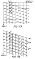
- the range processor 223 operates in the same way as does range processor 13 in the first embodiment. Also, linear range migration interpolator 77 interpolates points Ql, Q2, Q3 etc from points Pl, P2, P3 ( Figure 15A and Figure 15B) in the same way as does linear range migration interpolator 29 with reference to Figures 6, 7a, 7b.
- the interpolated data samples at points Q1, Q2, Q3 etc. of each range line are transferred to the shift register modules 33 of the azimuth processor 225, as they become available at the output of the linear range migration interpolator 77.
- the azimuth processor 225 can carry out azimuth integration by weighted summation of data samples in lines 179 parallel to axis y in Figure 15B. However, if the non-linear component of range migration 75 is not negligible, the azimuth processor 225 has to carry out weighted summation of samples along the curved paths 181 of Figure 15B.
- the linear range migration interpolator 77 is modified so that it provides the azimuth processor 225 with interpolated data in a saw-tooth edged region 185 as shown in Figure 16.
- the azimuth processor 25 includes an R - stage shift register arranged in modular sections 1331...133 B , each stage being adapted to accommodate all the bits comprising a single range line sample.
- the shift register 1331 etc. is associated with a memory arranged in modular sections 1391....139 B capable of storing R x M range line samples and a processing unit arranged in modular section 1371....137 B .
- the memory 139 is organised so as to be functionally equivalent to a memory in the form of the curved surface of a cylinder.
- First line i is clocked into the shift register 133 whilst at the same time processed data for range line (i-M-1) is clocked out of the shift register.
- the memory 139 holds range lines (i-1) to (i-M), and the processing unit 137 utilises this data to calculate processed data for range line (i-M).
- the data for range line i is transferred from the shift register 133 to the memory 139 where it overwrites the data for range line (i-M), and the data removed from the shift register 133 is replaced by processed data for line (i-M) from the processing unit 137.
- the data for the next range line (i+l) is then clocked into the register 133 and the processed data for range line (i-M), is clocked out of the register 133, and the cycle repeated.
- a shift register arrangement using two shift registers may be used, one for data input and the other for data output.
- Each shift register section 1331 is associated with a respective azimuth processing module (APM) 1351....135 B , each of which comprises a processing unit sections 1371 etc and a memory section 1391 etc.
- APM azimuth processing module
- the data in each memory section 139 cannot be azimuth processed. (i.e. correlated with reference coefficients) along columns of data in the memory section.
- the samples required for azimuth processing must be taken from several columns over the M rows.
- each processing unit section 137 includes a range migration interpolator in the form of a shift register (not shown) which interpolates samples on the range migration curves.
- the respective interpolator reads each row of each memory section, and the interpolated samples are generated by a weighting arrangement which operates on a group of the register locations.
- the shift register sections 133 into which the data samples from the linear range migration interpolator 77 are fed are connected in a ring by means of links 207, so that the start of each new line can be input at difference positions around the ring.
- the linear component of the range migration curve is thus dealt with by the linear range migration interpolator 77 and the variable entry/exit points for data, while the residual curved component of the range migration is dealt with by means of the shift register range migration interpolators (not shown) and the interconnections 149. Since the non-linear range migration effect is relatively small, each interpolator can carry out the interpolation to compute values of data samples along the range migration path by obtaining data only from its own memory section and from interpolators of the adjacent APMs.
- the difficulty encountered at the saw-tooth discontinuities referred to earlier is dealt with by stepping the input point along the shift register ring by the number of storage locations in the register equal to the height of the discontinuity.
- each interconnection 1491 to 149 B-1 between adjacent interpolators i.e. between adjacent processing unit sections 137 includes a switch arrangement Sl, S2 whereby the interconnection may be established or the interconnection broken and each end of the interconnection grounded.
- connections 149 O , 149 B are associated with a switching arrangement S3, S4 whereby the connections 149 O and 149 B may be connected together, or the connection between them broken and each connection 149 O , 149 B grounded.
- each link 2071 to 207 B-1 between adjacent shift register sections 133 includes a switching arrangement S5, S6 whereby the link may be established or the link broken and the output of the earlier section 133 connected to the output of the shift register as a whole and the input of the later section 133 connected to the input of the shift register as a whole.
- the input 207 O of the shift register section 1331 and the output 207 B of shift register section 133 B are associated with switiches S7, S8 whereby the input 207 O is connected to output 107 B or the connection is broken and the input 207 O is connected to the input of the whole shift register and output 107 B is connected to the output of the whole shift register 27.
- the switches S1 to S8 are operated by the system controller, to obtain the connection sequence of the processing unit sections 137, and connection sequence of the shift register sections 133 required for processing at any particular time.
- the connection between the input 2070 of shift register section 331 and the output 207 B of shift register section 133 B and the connection between connections 1490 and 149 B of processing unit sections 1371 and 137 B are both broken, and all interconnections 149 and links 207 are established.
- the connections 1490 and 149 B are then of course grounded, the data from the linear range migration interpolator 77 is entered into shift register section 1331, and output processed data is obtained from shift register section 133 B .
- FIG. 18 The overall operation of the arrangement of Figure 17 is illustrated in Figure 18.
- the data entry/exit points in the shift register ring rotate in discrete steps so that an APM 135 can process data in strips parallel to the linear component of range migration 73 (i.e. y axis).
- the strips of data processed by APM 135 B are marked as 203 and 205 in Figure 16.
- the slope of the linear component range migration 73 may change with time. Hence if the height of the discontinuity h d is tN, the value of the integer t may also change with time. Since the data/entry exit points are rotated by t APMs 135 at a discontinuity, the speed of rotation of the data entry/exit points around the shift register ring will change with the slope of the range migration line 73.
- the slope of the linear component of range migration 73 may be positive, as in the time period 215 of Figure 18, or may be negative as in the time period 219 of Figure 18.
- the slope is positive the points of data entry/exit of the shift register ring rotate, in discrete steps, in the same direction as the data (in the counter-clockwise direction in the configuration shown in Figure 17).
- the slope is negative the points of data entry/exit rotate in the direction opposite to that of data rotation (in the clockwise direction in the configuration shown in Figure 17).
- the height of the discontinuity h d between successive data blocks must be an integer multiple t of N. This can be achieved either by changing the width of each data block (all data blocks need not to be the same width) or by changing the slope of the linear component of range migration 73 in discrete steps. The latter does not give rise to any limitations in the amounts of range migration that can be corrected by the processor since any residual range migration effects can be removed using the interpolators 45 in the ring of APMs 135.
- Fault tolerance can be introduced in the ring processor of Figure 17 by using redundant APMs 135 and redundant shift register sections 133 in the ring.
- the invention is particularly applicable to radar apparatus which operates in the microwave region of the electromagnetic spectrum, it is also applicable to other types of radar, for example, acoustic (sonar) or optical radar.
Landscapes
- Engineering & Computer Science (AREA)
- Remote Sensing (AREA)
- Radar, Positioning & Navigation (AREA)
- Physics & Mathematics (AREA)
- Signal Processing (AREA)
- Electromagnetism (AREA)
- Computer Networks & Wireless Communication (AREA)
- General Physics & Mathematics (AREA)
- Radar Systems Or Details Thereof (AREA)
Applications Claiming Priority (6)
| Application Number | Priority Date | Filing Date | Title |
|---|---|---|---|
| GB878726390A GB8726390D0 (en) | 1987-11-11 | 1987-11-11 | Radar systems |
| GB8726390 | 1987-11-11 | ||
| GB888802906A GB8802906D0 (en) | 1988-02-09 | 1988-02-09 | Radar system |
| GB8802906 | 1988-02-09 | ||
| GB888809950A GB8809950D0 (en) | 1988-04-27 | 1988-04-27 | Radar system |
| GB8809950 | 1988-04-27 |
Publications (2)
| Publication Number | Publication Date |
|---|---|
| EP0316148A2 true EP0316148A2 (de) | 1989-05-17 |
| EP0316148A3 EP0316148A3 (de) | 1990-08-01 |
Family
ID=27263660
Family Applications (1)
| Application Number | Title | Priority Date | Filing Date |
|---|---|---|---|
| EP88310535A Withdrawn EP0316148A3 (de) | 1987-11-11 | 1988-11-09 | Rechner für ein Radarsystem |
Country Status (3)
| Country | Link |
|---|---|
| US (1) | US4967200A (de) |
| EP (1) | EP0316148A3 (de) |
| GB (1) | GB2212355B (de) |
Cited By (2)
| Publication number | Priority date | Publication date | Assignee | Title |
|---|---|---|---|---|
| WO1993002368A1 (en) * | 1991-07-15 | 1993-02-04 | Macdonald Dettwiler And Associates Ltd. | Synthetic aperture radar processor to handle large squint with high phase and geometric accuracy |
| WO2002101409A3 (en) * | 2001-06-13 | 2003-09-04 | Raytheon Co | System and method for processing squint mapped synthetic aperture radar data |
Families Citing this family (6)
| Publication number | Priority date | Publication date | Assignee | Title |
|---|---|---|---|---|
| DE4026874C1 (de) * | 1990-08-25 | 1992-04-30 | Deutsche Forschungsanstalt Fuer Luft- Und Raumfahrt Ev, 5300 Bonn, De | |
| DE4122592C1 (de) * | 1991-07-08 | 1993-01-28 | Deutsche Forschungsanstalt Fuer Luft- Und Raumfahrt Ev, 5300 Bonn, De | |
| US5463397A (en) * | 1993-10-25 | 1995-10-31 | Hughes Aircraft Company | Hyper-precision SAR interferometry using a dual-antenna multi-pass SAR system |
| US6720906B2 (en) * | 2001-07-12 | 2004-04-13 | Honeywell International Inc. | Constant altitude weather and all weather display |
| US9880277B2 (en) * | 2014-05-01 | 2018-01-30 | Utah State University Research Foundation | Synthetic aperture radar processing |
| US10936487B2 (en) * | 2018-03-12 | 2021-03-02 | Beijing Horizon Information Technology Co., Ltd. | Methods and apparatus for using circular addressing in convolutional operation |
Family Cites Families (4)
| Publication number | Priority date | Publication date | Assignee | Title |
|---|---|---|---|---|
| US4227194A (en) * | 1971-01-04 | 1980-10-07 | Hughes Aircraft Company | Synthetic array processor |
| US4219811A (en) * | 1975-02-07 | 1980-08-26 | Hughes Aircraft Company | Synthetic array autofocus system |
| US4132989A (en) * | 1977-10-18 | 1979-01-02 | Nasa | Azimuth correlator for real-time synthetic aperture radar image processing |
| US4471357A (en) * | 1981-10-26 | 1984-09-11 | The United States Of America As Represented By The Administrator Of The National Aeronautics And Space Administration | Pipelined digital SAR azimuth correlator using hybrid FFT/transversal filter |
-
1988
- 1988-11-09 GB GB8826242A patent/GB2212355B/en not_active Expired - Lifetime
- 1988-11-09 EP EP88310535A patent/EP0316148A3/de not_active Withdrawn
- 1988-11-10 US US07/269,732 patent/US4967200A/en not_active Expired - Fee Related
Cited By (2)
| Publication number | Priority date | Publication date | Assignee | Title |
|---|---|---|---|---|
| WO1993002368A1 (en) * | 1991-07-15 | 1993-02-04 | Macdonald Dettwiler And Associates Ltd. | Synthetic aperture radar processor to handle large squint with high phase and geometric accuracy |
| WO2002101409A3 (en) * | 2001-06-13 | 2003-09-04 | Raytheon Co | System and method for processing squint mapped synthetic aperture radar data |
Also Published As
| Publication number | Publication date |
|---|---|
| GB8826242D0 (en) | 1988-12-14 |
| GB2212355A (en) | 1989-07-19 |
| EP0316148A3 (de) | 1990-08-01 |
| US4967200A (en) | 1990-10-30 |
| GB2212355B (en) | 1991-12-18 |
Similar Documents
| Publication | Publication Date | Title |
|---|---|---|
| US4132989A (en) | Azimuth correlator for real-time synthetic aperture radar image processing | |
| US4471357A (en) | Pipelined digital SAR azimuth correlator using hybrid FFT/transversal filter | |
| US6695783B2 (en) | Multiline ultrasound beamformers | |
| US4174514A (en) | Parallel partitioned serial neighborhood processors | |
| EP0395863A2 (de) | Apertursynthetisiertes Radiometer, welches digitale Strahlenbündelungstechnik verwendet | |
| US5191344A (en) | Method for digital generation of sar images and apparatus for carrying out said method | |
| US5608404A (en) | Imaging synthetic aperture radar | |
| WO1997039420A1 (en) | Computationally efficient digital image warping | |
| EP1994429A1 (de) | Lineararray-ultraschallwandler mit veränderlichen patchgrenzen | |
| US4967200A (en) | Processor for radar system | |
| US4910520A (en) | High speed synthetic radar processing system | |
| US5329283A (en) | Synthetic aperture radar digital signal processor | |
| EP0227614A2 (de) | Signalverarbeitungsvorrichtung für Radar mit synthetischer Apertur, insbesondere geeignet für Parallelberechnung | |
| Dall et al. | Real-time processor for the Danish airborne SAR | |
| KR20230053405A (ko) | 레인지 도플러 알고리즘 기반 sar 영상 형성 장치 및 방법 | |
| US4879559A (en) | Azimuth processor for SAR system having plurality of interconnected processing modules | |
| EP0006748B1 (de) | Vorrichtung und Verfahren zur Erzeugung einer Transformation einer ersten Datenmatrix zur Bildung einer zweiten Datenmatrix | |
| EP0786738B1 (de) | Bildverarbeitungssystem und Bildverarbeitungsverfahren | |
| EP0355158B1 (de) | Verfahren und gerät zur verarbeitung von bemusterten datensignalen | |
| Bonfield et al. | Synthetic-aperture-radar real-time processing | |
| Wong et al. | A novel technique for the processing of short-dwell spotlight SAR data | |
| Przytula et al. | Implementation of synthetic aperture radar algorithms on a systolic/cellular architecture | |
| EP0409219A2 (de) | Rekursives Bilderzeugungssystem mittels Radar mit synthetischer Apertur in Spotlight-Modus | |
| Przytula et al. | Parallel implementation of synthetic aperture radar algorithms | |
| Spielbauer et al. | Development of a real-time airborne SAR processor using a subaperture approach |
Legal Events
| Date | Code | Title | Description |
|---|---|---|---|
| PUAI | Public reference made under article 153(3) epc to a published international application that has entered the european phase |
Free format text: ORIGINAL CODE: 0009012 |
|
| AK | Designated contracting states |
Kind code of ref document: A2 Designated state(s): AT BE CH DE ES FR GR IT LI LU NL SE |
|
| PUAL | Search report despatched |
Free format text: ORIGINAL CODE: 0009013 |
|
| AK | Designated contracting states |
Kind code of ref document: A3 Designated state(s): AT BE CH DE ES FR GR IT LI LU NL SE |
|
| 17P | Request for examination filed |
Effective date: 19910123 |
|
| STAA | Information on the status of an ep patent application or granted ep patent |
Free format text: STATUS: THE APPLICATION IS DEEMED TO BE WITHDRAWN |
|
| 18D | Application deemed to be withdrawn |
Effective date: 19920602 |