EP0316227A1 - Münzbetätigte Vorrichtung - Google Patents
Münzbetätigte Vorrichtung Download PDFInfo
- Publication number
- EP0316227A1 EP0316227A1 EP88402794A EP88402794A EP0316227A1 EP 0316227 A1 EP0316227 A1 EP 0316227A1 EP 88402794 A EP88402794 A EP 88402794A EP 88402794 A EP88402794 A EP 88402794A EP 0316227 A1 EP0316227 A1 EP 0316227A1
- Authority
- EP
- European Patent Office
- Prior art keywords
- receptacle
- partition
- shutter
- removable
- machine
- Prior art date
- Legal status (The legal status is an assumption and is not a legal conclusion. Google has not performed a legal analysis and makes no representation as to the accuracy of the status listed.)
- Granted
Links
Images

Classifications
-
- G—PHYSICS
- G07—CHECKING-DEVICES
- G07F—COIN-FREED OR LIKE APPARATUS
- G07F9/00—Details other than those peculiar to special kinds or types of apparatus
- G07F9/06—Coin boxes
Definitions
- the present invention relates to a machine actuated by the introduction of coins and more particularly an embodiment of a coin storage chest for such a machine.
- the pay parking control machines often called parking meters, which are most often encountered are installed along public roads to allow motorists to pay the required parking tax on the one hand and Parking attendants are responsible for checking that users of parked vehicles have actually paid this tax.
- machines in which payment is made using memory cards there are three types of machines: machines in which payment is made using memory cards; of machines in which payment is made using coins; and finally mixed machines that allow both types of payment.
- the invention of course relates to the last two types of machines.
- the machine must have a receptacle for storing the coins. On the one hand this receptacle must provide effective protection against vandalism, on the other hand it must allow easy collection of coins.
- the coin receptacle is of the type described in European patent 44,754 issued in the name of FLONIC.
- the receptacle remains permanently in the housing of the parking machine.
- the bottom of the case also constitutes at least part of the bottom of the receptacle. This bottom is provided with a collection orifice which is closed by a sliding shutter. To proceed with the collection, it suffices to place a container for the collection of coins below the orifice and to operate the shutter to clear the collection orifice.
- the removable partitions of the receptacle can only be dismantled when the collection shutter is in the open position.
- the attendant who holds both the collection means for moving the shutter and the access key to the housing of the parking machine can access the interior of the receptacle, this possibility not existing for the attendants to simple maintenance.
- An object of the invention is to provide a parking machine in which the interior of the coin receptacle can only be accessed when the receptacle for collecting the receptacle is in the open position.
- the machine actuated by the introduction of coins comprises a box provided with a bottom and in the case a receptacle for collecting the coins introduced into the machine, the receptacle comprising a bottom of which at least one part is common with the bottom of said housing, the common part comprising a collection orifice opening out of the housing and at least one removable partition separating the interior of the receptacle from the rest of the interior of the housing, and a movable shutter in rectilinear translation between a first position in which it closes the orifice and a second position in which the orifice is released, and it is characterized in that at least one removable partition of the receptacle is not perpendicular to the direction of movement shutter, and in that in the receptacle the machine comprises a movable return member occupying a first position in which a part of the member penetrates into the removable partition to lock the latter and a second position in which the member does not lock the removable partition, the shutter when it goes from
- the removable partition is not perpendicular to the direction of movement of the shutter and preferably substantially parallel to this direction, the latter is effectively locked when the shutter is in the closed position, thanks to the presence of the movable member which is actuated by the movement of the shutter.
- FIG. 1 shows, in a simplified form, a paid parking control machine comprising a receptacle for collecting coins according to the invention.
- the machine comprises a box 10 of generally rectangular parallelepiped shape mounted on a foot 12.
- the box 10 has a bottom 14, an upper wall 16, two side walls 18 and 20 and a rear wall 22.
- the front wall is partly formed by a door 24 closed by a lock 26.
- the door 24 has been shown in dotted lines to allow a better view of the interior of the case 10.
- the case internally comprises a certain number of members which are not part of the invention and which have therefore not been shown in FIG. 1. Mention may be made of a coin selector, a pre-collection system of coins and "coin return", a reel of paper for printing tickets, a printer, for example a thermal printer, and electronic circuits for controlling these various organs.
- a receptacle 30 for storing coins after they have passed through the coin selector and the pre-collection device.
- the receptacle 30 has a general rectangular parallelepiped shape.
- the bottom wall and the rear wall of the receptacle 30 are respectively constituted by a part of the bottom 14, and a part of the rear wall 22 of the housing 10.
- one of its side walls is formed by a part of the side wall 20 of the box 10.
- the other walls of the receptacle 30, which separate it from the rest of the interior of the housing 10, are specific to the receptacle.
- the partitions 34 and 36 include a front wall 32 integral with the bottom 14 and the side wall 20 of the housing, and an upper wall and a second side wall formed respectively by removable partitions 34 and 36.
- the upper partition 34 is provided with an opening 38 for the introduction of the coins into the receptacle, and the partition 36 is substantially parallel to the direction of movement of the shutter 42.
- the bottom 24 of the housing 10, in its part, which also forms the bottom of the receptacle 30 is provided with an orifice 40 shown diagrammatically in FIG. 1.
- the orifice 40 can be closed by a shutter 42 which can be operated in rectilinear translation in the direction of the arrow F.
- the shutter 42 is also provided with an orifice 44 having the same dimensions as the orifice 40. In the position shown on Figure 1, the shutter 42 is fully pushed towards the rear of the machine. The two orifices 40 and 44 do not overlap at all. The orifice 40 is therefore closed. If the shutter 42 is pulled forward, the two orifices 40 and 44 are superimposed and it is therefore possible to collect the parts contained in the receptacle 30.
- Figure 1 shows, in a simplified form that, in the receptacle 30, a member 50 pivotally mounted on the bottom of the receptacle 30 can be controlled in movement by the shutter 42, so that it locks on the bottom 14 of the housing 10 the partition 36.
- the lateral partition 36 locks the upper partition 34.
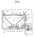
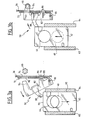
- FIGS. 2, 3a and 3b a preferred embodiment of the receptacle 30 will be described in more detail.
- FIG. 2 shows in more detail the structure of the receptacle 30.
- the bottom wall 14 of the housing in the area of the orifice 40 is surmounted by a counter plate 60 fixed to the bottom 14 by two parallel strips 62 and 64.
- the shutter 42 can slide between the bottom 14 and the counter plate 60 while being guided laterally by the strips 62 and 64.
- the counter plate 60 is pierced with an orifice 66 which is superimposed exactly on the orifice 40.
- the lower end 68 a of the hopper 68 is held opposite the orifice 66 of the counter plate by a flange 70 formed on the counter plate.
- a rib 72 of reduced height is welded to the bottom 14 parallel to the partition 36 such that the lower part 36 of the partition is pressed against the rib 72, the latter being disposed Enterieur the receptacle 30.
- the locking member 50 is pivotally mounted about an axis 80 integral with the bottom 14 of the housing.
- the member 50 comprises a lever portion 82.
- a heel 88 projects from the other edge of the lever.
- the heel 88 is arranged in the plane of the obturator 42.
- the heel 88 is intended to cooperate with the rear edge 90 of the shutter 42 and with its lateral edge 92.
- the lower part 36 has removable partition 36 and the rib 72 are provided with two slots respectively 94, 96, and 98, 100. When the partition 36 is in the locked position, the slots 94, 98 and 96, 100 coincide respectively.
- FIG. 2 shows better how the locking of the partition 36 already partially achieved by the member 50 is completed and how the locking of the partition 36 also ensures the locking of the upper partition 34.
- the rear edge of the partition 36 is engaged between two angle elements 102 and 104 secured to the rear partition 22 of the housing.
- the upper edge 36 has a partition 36 is curled.
- the edge 34 a of the partition 34 is engaged in a slide 106 secured to the partition 20 of the housing, and the partition 34 rests in part on an angle element 108 secured to the rear partition 22 of the housing.
- the upper edge 36 a of the partition 36 is disposed above the edge 34 b of the partition 34.
- the member 50 can be freely brought into the position it occupies in this same figure.
- the partition 36 can then be removed by lifting it upwards and the partition 34 can also be removed. It is then possible to easily access the interior of the receptacle 30 to carry out the necessary interventions and in particular access the mechanism of a lock disposed in the receptacle. This lock is used to lock the shutter in its closed position.
- the mechanical connection between the foot 12 and the housing 10 is achieved by sets, studs-nuts such as the assembly 110.
- the nut 110 is located inside the casing 10 but outside the receptacle 30. It would therefore be possible, after opening the door 20, to unscrew the nuts 110 to separate the casing from its foot.
- the spout 84 has a sufficient length so that, when the member 50 is in the locking position, the spout 84 covers the head of the stud 110. Thus, even when the front door is open, it it is not possible to unscrew the nut protected by the spout 84.
- the removable partitions 34 and 36 could be constituted in another way, for example formed by one and the same piece, the separation in two having the sole purpose of facilitating the access operation inside. of the receptacle.
- the partition 34 could have been fixed and secured to the housing, only the lateral partition 36 being removable.
- the partition 36 is fixed and integral with the housing, only the upper partition 34 being removable.
- the upper partition 34 is provided with two vertical tabs with the end of which the two slots are formed in which the two nozzles 84 and 86 of the locking member penetrate when the latter is in the suitable position.
- the movable return member 50 may not be pivotable. This could be a moving part guided in translation in a direction perpendicular to the removable partition.
- the shutter comprises a ramp which converts the movement of the shutter into a movement of the return member to lock the removable partition.
- the machine provided with the receptacle according to the invention is not necessarily a parking terminal. As already indicated, it can be any machine activated by the introduction of coins. It has not been described how the shutter 42 can be moved. Preferably the shutter is moved using the head of the coin collecting device as explained in detail in the European patent already cited.
Landscapes
- Physics & Mathematics (AREA)
- General Physics & Mathematics (AREA)
- Control Of Vending Devices And Auxiliary Devices For Vending Devices (AREA)
- Pinball Game Machines (AREA)
- Slot Machines And Peripheral Devices (AREA)
Applications Claiming Priority (2)
| Application Number | Priority Date | Filing Date | Title |
|---|---|---|---|
| FR8715479A FR2622997B1 (fr) | 1987-11-09 | 1987-11-09 | Machine actionnee par l'introduction de pieces de monnaie |
| FR8715479 | 1987-11-09 |
Publications (2)
| Publication Number | Publication Date |
|---|---|
| EP0316227A1 true EP0316227A1 (de) | 1989-05-17 |
| EP0316227B1 EP0316227B1 (de) | 1992-08-26 |
Family
ID=9356610
Family Applications (1)
| Application Number | Title | Priority Date | Filing Date |
|---|---|---|---|
| EP19880402794 Expired - Lifetime EP0316227B1 (de) | 1987-11-09 | 1988-11-07 | Münzbetätigte Vorrichtung |
Country Status (4)
| Country | Link |
|---|---|
| EP (1) | EP0316227B1 (de) |
| DE (1) | DE3874089T2 (de) |
| ES (1) | ES2035343T3 (de) |
| FR (1) | FR2622997B1 (de) |
Cited By (1)
| Publication number | Priority date | Publication date | Assignee | Title |
|---|---|---|---|---|
| ES2242511A1 (es) * | 2003-11-06 | 2005-11-01 | Norbert Joseph Rodriguez | Caja recaudadora para telefonos publicos de cabinas. |
Citations (6)
| Publication number | Priority date | Publication date | Assignee | Title |
|---|---|---|---|---|
| US2580752A (en) * | 1946-12-18 | 1952-01-01 | Johnson Fare Box Co | Self-locking cashbox |
| FR2107280A5 (de) * | 1970-09-04 | 1972-05-05 | Associated Automation | |
| US3851942A (en) * | 1973-12-03 | 1974-12-03 | Reed Ind Inc | Meter box with vault latch |
| EP0044754A1 (de) * | 1980-06-11 | 1982-01-27 | Societe Flonic | Verkaufsautomat und dazugehörige Einrichtung zum Sammeln des durch den Automaten kassierten Geldes |
| US4372479A (en) * | 1980-04-03 | 1983-02-08 | Sciortino August M | Self-locking covered coin receptacle and automatic reset mechanism therefor |
| FR2587134A1 (fr) * | 1985-09-12 | 1987-03-13 | Landis Gyr | Compartiment caisse en particulier pour appareils a monnaie tels que les publiphones |
-
1987
- 1987-11-09 FR FR8715479A patent/FR2622997B1/fr not_active Expired - Lifetime
-
1988
- 1988-11-07 EP EP19880402794 patent/EP0316227B1/de not_active Expired - Lifetime
- 1988-11-07 ES ES88402794T patent/ES2035343T3/es not_active Expired - Lifetime
- 1988-11-07 DE DE19883874089 patent/DE3874089T2/de not_active Expired - Fee Related
Patent Citations (6)
| Publication number | Priority date | Publication date | Assignee | Title |
|---|---|---|---|---|
| US2580752A (en) * | 1946-12-18 | 1952-01-01 | Johnson Fare Box Co | Self-locking cashbox |
| FR2107280A5 (de) * | 1970-09-04 | 1972-05-05 | Associated Automation | |
| US3851942A (en) * | 1973-12-03 | 1974-12-03 | Reed Ind Inc | Meter box with vault latch |
| US4372479A (en) * | 1980-04-03 | 1983-02-08 | Sciortino August M | Self-locking covered coin receptacle and automatic reset mechanism therefor |
| EP0044754A1 (de) * | 1980-06-11 | 1982-01-27 | Societe Flonic | Verkaufsautomat und dazugehörige Einrichtung zum Sammeln des durch den Automaten kassierten Geldes |
| FR2587134A1 (fr) * | 1985-09-12 | 1987-03-13 | Landis Gyr | Compartiment caisse en particulier pour appareils a monnaie tels que les publiphones |
Cited By (2)
| Publication number | Priority date | Publication date | Assignee | Title |
|---|---|---|---|---|
| ES2242511A1 (es) * | 2003-11-06 | 2005-11-01 | Norbert Joseph Rodriguez | Caja recaudadora para telefonos publicos de cabinas. |
| ES2242511B1 (es) * | 2003-11-06 | 2006-11-01 | Norbert Joseph Rodriguez | Caja recaudadora para telefonos publicos de cabinas. |
Also Published As
| Publication number | Publication date |
|---|---|
| FR2622997A1 (fr) | 1989-05-12 |
| ES2035343T3 (es) | 1993-04-16 |
| EP0316227B1 (de) | 1992-08-26 |
| DE3874089T2 (de) | 1993-01-14 |
| DE3874089D1 (de) | 1992-10-01 |
| FR2622997B1 (fr) | 1991-12-27 |
Similar Documents
| Publication | Publication Date | Title |
|---|---|---|
| EP1941821A1 (de) | Verteiler von nebeneinander angeordneten Rollen, der mit einer unteren Schiebeverschlussklappe ausgestattet ist | |
| FR2838034A1 (fr) | Distributeur de conditionnement un a un pour magasins | |
| EP0168279B1 (de) | Gehäuse, insbesondere für einen Elektrizitätszähler oder ähnliches | |
| FR2700803A1 (fr) | Dispositif pour commander l'ouverture/fermeture d'une pluralité de portes donnant accès chacune à une enceinte. | |
| EP0044754B1 (de) | Verkaufsautomat und dazugehörige Einrichtung zum Sammeln des durch den Automaten kassierten Geldes | |
| EP1340202A1 (de) | Gesichertes münzgerät | |
| CH630192A5 (fr) | Boite d'entreposage de billets. | |
| EP0316227B1 (de) | Münzbetätigte Vorrichtung | |
| FR2721912A1 (fr) | Dispositif de verrouillage du couvercle d'un bac destine a etre vide par basculement | |
| EP0320335B1 (de) | Abnehmbarer Münzvorratsbehälter für Münzautomaten | |
| EP1805731B1 (de) | Mit wechselbarer münzaufnahme ausgestattete geldhandhabungseinheit | |
| EP0022694B1 (de) | Kassette für einen Stapel von Blättern in einer Maschine zum Abgeben derselben | |
| EP0294276B1 (de) | Kombinationsschloss mit Sperrscheiben und automatischer Löschung der Kombination beim Schliessen | |
| EP3585961B1 (de) | Gehäuse mit schieber zur verriegelung und immobilisierung in einer geschlossenen oder offenen position | |
| FR2586126A1 (fr) | Distributeur automatique d'articles consommables concu pour etre pose sur un comptoir | |
| CH597809A5 (en) | Divided letter and parcel box | |
| FR2587134A1 (fr) | Compartiment caisse en particulier pour appareils a monnaie tels que les publiphones | |
| EP1285414A1 (de) | Ausgabeautomat für einzelne gegenstände | |
| FR2669310A1 (fr) | Dispositif pour stocker des objets. | |
| CH339763A (fr) | Appareil collecteur de pièces de monnaie | |
| FR2543206A1 (fr) | Coffre-fort a enceinte incorporee | |
| CA2611553A1 (fr) | Machine de distribution de produits et/ou de services contre paiement par billets | |
| WO2004100160A2 (fr) | Dispositif pour boitier antivol | |
| FR2591570A1 (fr) | Couvercle de securite amovible | |
| BE905632A (fr) | Appareil de depot. |
Legal Events
| Date | Code | Title | Description |
|---|---|---|---|
| PUAI | Public reference made under article 153(3) epc to a published international application that has entered the european phase |
Free format text: ORIGINAL CODE: 0009012 |
|
| AK | Designated contracting states |
Kind code of ref document: A1 Designated state(s): BE CH DE ES GB IT LI NL SE |
|
| 17P | Request for examination filed |
Effective date: 19890628 |
|
| 17Q | First examination report despatched |
Effective date: 19910528 |
|
| GRAA | (expected) grant |
Free format text: ORIGINAL CODE: 0009210 |
|
| AK | Designated contracting states |
Kind code of ref document: B1 Designated state(s): BE CH DE ES GB IT LI NL SE |
|
| ITF | It: translation for a ep patent filed | ||
| REF | Corresponds to: |
Ref document number: 3874089 Country of ref document: DE Date of ref document: 19921001 |
|
| GBT | Gb: translation of ep patent filed (gb section 77(6)(a)/1977) | ||
| REG | Reference to a national code |
Ref country code: ES Ref legal event code: FG2A Ref document number: 2035343 Country of ref document: ES Kind code of ref document: T3 |
|
| PLBE | No opposition filed within time limit |
Free format text: ORIGINAL CODE: 0009261 |
|
| STAA | Information on the status of an ep patent application or granted ep patent |
Free format text: STATUS: NO OPPOSITION FILED WITHIN TIME LIMIT |
|
| 26N | No opposition filed | ||
| EAL | Se: european patent in force in sweden |
Ref document number: 88402794.7 |
|
| PGFP | Annual fee paid to national office [announced via postgrant information from national office to epo] |
Ref country code: SE Payment date: 20011106 Year of fee payment: 14 |
|
| PGFP | Annual fee paid to national office [announced via postgrant information from national office to epo] |
Ref country code: GB Payment date: 20011107 Year of fee payment: 14 |
|
| PGFP | Annual fee paid to national office [announced via postgrant information from national office to epo] |
Ref country code: DE Payment date: 20011119 Year of fee payment: 14 |
|
| PGFP | Annual fee paid to national office [announced via postgrant information from national office to epo] |
Ref country code: ES Payment date: 20011122 Year of fee payment: 14 |
|
| PGFP | Annual fee paid to national office [announced via postgrant information from national office to epo] |
Ref country code: NL Payment date: 20011129 Year of fee payment: 14 |
|
| PGFP | Annual fee paid to national office [announced via postgrant information from national office to epo] |
Ref country code: CH Payment date: 20011130 Year of fee payment: 14 |
|
| REG | Reference to a national code |
Ref country code: GB Ref legal event code: IF02 |
|
| PGFP | Annual fee paid to national office [announced via postgrant information from national office to epo] |
Ref country code: BE Payment date: 20020123 Year of fee payment: 14 |
|
| PG25 | Lapsed in a contracting state [announced via postgrant information from national office to epo] |
Ref country code: GB Free format text: LAPSE BECAUSE OF NON-PAYMENT OF DUE FEES Effective date: 20021107 |
|
| PG25 | Lapsed in a contracting state [announced via postgrant information from national office to epo] |
Ref country code: SE Free format text: LAPSE BECAUSE OF NON-PAYMENT OF DUE FEES Effective date: 20021108 Ref country code: ES Free format text: LAPSE BECAUSE OF NON-PAYMENT OF DUE FEES Effective date: 20021108 |
|
| PG25 | Lapsed in a contracting state [announced via postgrant information from national office to epo] |
Ref country code: LI Free format text: LAPSE BECAUSE OF NON-PAYMENT OF DUE FEES Effective date: 20021130 Ref country code: CH Free format text: LAPSE BECAUSE OF NON-PAYMENT OF DUE FEES Effective date: 20021130 Ref country code: BE Free format text: LAPSE BECAUSE OF NON-PAYMENT OF DUE FEES Effective date: 20021130 |
|
| BERE | Be: lapsed |
Owner name: *SCHLUMBERGER INDUSTRIES Effective date: 20021130 |
|
| PG25 | Lapsed in a contracting state [announced via postgrant information from national office to epo] |
Ref country code: NL Free format text: LAPSE BECAUSE OF NON-PAYMENT OF DUE FEES Effective date: 20030601 |
|
| PG25 | Lapsed in a contracting state [announced via postgrant information from national office to epo] |
Ref country code: DE Free format text: LAPSE BECAUSE OF NON-PAYMENT OF DUE FEES Effective date: 20030603 |
|
| GBPC | Gb: european patent ceased through non-payment of renewal fee | ||
| EUG | Se: european patent has lapsed | ||
| REG | Reference to a national code |
Ref country code: CH Ref legal event code: PL |
|
| NLV4 | Nl: lapsed or anulled due to non-payment of the annual fee |
Effective date: 20030601 |
|
| REG | Reference to a national code |
Ref country code: ES Ref legal event code: FD2A Effective date: 20031213 |
|
| PG25 | Lapsed in a contracting state [announced via postgrant information from national office to epo] |
Ref country code: IT Free format text: LAPSE BECAUSE OF NON-PAYMENT OF DUE FEES Effective date: 20051107 |