EP0316242A1 - Platte für die Konstruktion von Möbeln - Google Patents
Platte für die Konstruktion von Möbeln Download PDFInfo
- Publication number
- EP0316242A1 EP0316242A1 EP88420370A EP88420370A EP0316242A1 EP 0316242 A1 EP0316242 A1 EP 0316242A1 EP 88420370 A EP88420370 A EP 88420370A EP 88420370 A EP88420370 A EP 88420370A EP 0316242 A1 EP0316242 A1 EP 0316242A1
- Authority
- EP
- European Patent Office
- Prior art keywords
- plate
- support
- panel according
- panel
- edge
- Prior art date
- Legal status (The legal status is an assumption and is not a legal conclusion. Google has not performed a legal analysis and makes no representation as to the accuracy of the status listed.)
- Withdrawn
Links
- 238000010276 construction Methods 0.000 title claims description 14
- 230000002093 peripheral effect Effects 0.000 claims abstract description 9
- 239000000872 buffer Substances 0.000 claims description 16
- 238000009432 framing Methods 0.000 claims description 11
- 230000035939 shock Effects 0.000 claims description 9
- 239000011435 rock Substances 0.000 claims description 6
- 238000013016 damping Methods 0.000 claims description 4
- 239000013013 elastic material Substances 0.000 claims description 3
- 239000000463 material Substances 0.000 claims description 3
- 230000001681 protective effect Effects 0.000 claims description 2
- 239000004579 marble Substances 0.000 description 4
- -1 for example Substances 0.000 description 2
- 239000010438 granite Substances 0.000 description 2
- 238000004519 manufacturing process Methods 0.000 description 2
- 229920001296 polysiloxane Polymers 0.000 description 2
- 239000004575 stone Substances 0.000 description 2
- 239000000853 adhesive Substances 0.000 description 1
- 230000001070 adhesive effect Effects 0.000 description 1
- 239000011324 bead Substances 0.000 description 1
- 230000000295 complement effect Effects 0.000 description 1
- 230000006835 compression Effects 0.000 description 1
- 238000007906 compression Methods 0.000 description 1
- 239000004035 construction material Substances 0.000 description 1
- 239000003292 glue Substances 0.000 description 1
- 238000012986 modification Methods 0.000 description 1
- 230000004048 modification Effects 0.000 description 1
- 238000005498 polishing Methods 0.000 description 1
- 229920001225 polyester resin Polymers 0.000 description 1
- 239000004645 polyester resin Substances 0.000 description 1
- 239000011148 porous material Substances 0.000 description 1
- 230000003252 repetitive effect Effects 0.000 description 1
- 230000000284 resting effect Effects 0.000 description 1
- 239000007787 solid Substances 0.000 description 1
- 238000004381 surface treatment Methods 0.000 description 1
- 239000002023 wood Substances 0.000 description 1
Images

Classifications
-
- E—FIXED CONSTRUCTIONS
- E06—DOORS, WINDOWS, SHUTTERS, OR ROLLER BLINDS IN GENERAL; LADDERS
- E06B—FIXED OR MOVABLE CLOSURES FOR OPENINGS IN BUILDINGS, VEHICLES, FENCES OR LIKE ENCLOSURES IN GENERAL, e.g. DOORS, WINDOWS, BLINDS, GATES
- E06B5/00—Doors, windows, or like closures for special purposes; Border constructions therefor
- E06B5/006—Doors, windows, or like closures for special purposes; Border constructions therefor for furniture
-
- A—HUMAN NECESSITIES
- A47—FURNITURE; DOMESTIC ARTICLES OR APPLIANCES; COFFEE MILLS; SPICE MILLS; SUCTION CLEANERS IN GENERAL
- A47B—TABLES; DESKS; OFFICE FURNITURE; CABINETS; DRAWERS; GENERAL DETAILS OF FURNITURE
- A47B88/00—Drawers for tables, cabinets or like furniture; Guides for drawers
- A47B88/90—Constructional details of drawers
- A47B88/944—Drawers characterised by the front panel
-
- A—HUMAN NECESSITIES
- A47—FURNITURE; DOMESTIC ARTICLES OR APPLIANCES; COFFEE MILLS; SPICE MILLS; SUCTION CLEANERS IN GENERAL
- A47B—TABLES; DESKS; OFFICE FURNITURE; CABINETS; DRAWERS; GENERAL DETAILS OF FURNITURE
- A47B96/00—Details of cabinets, racks or shelf units not covered by a single one of groups A47B43/00 - A47B95/00; General details of furniture
- A47B96/20—Furniture panels or like furniture elements
- A47B96/201—Edge features
-
- A—HUMAN NECESSITIES
- A47—FURNITURE; DOMESTIC ARTICLES OR APPLIANCES; COFFEE MILLS; SPICE MILLS; SUCTION CLEANERS IN GENERAL
- A47B—TABLES; DESKS; OFFICE FURNITURE; CABINETS; DRAWERS; GENERAL DETAILS OF FURNITURE
- A47B96/00—Details of cabinets, racks or shelf units not covered by a single one of groups A47B43/00 - A47B95/00; General details of furniture
- A47B96/20—Furniture panels or like furniture elements
- A47B96/205—Composite panels, comprising several elements joined together
Definitions
- the present invention relates to the technical field of construction materials, of the decorative or ornamental type, which is more particularly in the form of panels of various sizes and shapes and intended to ensure the development or construction of products or objects, exclusively or not utilitarian and / or aesthetic, such as, for example, furniture.
- the object of the present invention is more particularly aimed at construction panels made up or coated with a rock, such as, for example, stone, marble or granite.
- patent application EP 0 151 406 proposes support elements intended for the manufacture of furniture, constituted by two marble plates glued together by a layer of polyester resin interposed between the plates.
- these support elements are not suitable, because of their structure, for constituting furniture or parts of furniture, intended to be subjected, directly or indirectly, to repetitive or accidental vibrations and / or shocks. This is the case, in particular, of mobile joinery, such as doors and drawers for furniture.
- the prior art also proposes, by patent application CH-A 487 623 , a construction element for furniture, comprising a cross-sectional cross-section frame in "U" shape, provided with projections anchored in a plate serving as support for a decorative panel.
- a building element is in no way designed and adapted to receive a decorative panel made of a rock, because of the structure of these elements which does not make it possible to solve the problems of support, deformation and breaking of the rock.
- the invention aims, precisely, to remedy the drawbacks of the prior art by proposing a panel for the construction of furniture comprising a decorative plate made of a rock and specially designed to withstand the shocks and vibrations to which it is subjected.
- the invention also aims to provide a panel adapted more particularly for the construction of mobile joinery.
- the invention also aims to provide a simple construction panel and having a manifest decorative appearance.
- the construction panel according to the invention is characterized in that it comprises: - a framing border fixed on the support, having a support rim of the plate and delimiting, with the edge of the plate, a peripheral clearance ensuring freedom of movement of the plate according to its plane, - And interposition means constituted by at least two shock and vibration damping pads allowing freedom of movement of the plate according to its plane and exerting a pressure force perpendicular to the plane of the plate to keep the plate in support against the edge of the frame border.
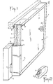
- Fig. 1 illustrates an embodiment of a panel according to the invention, suitable for the partial or complete construction of furniture, in the general sense, and, in particular, kitchen furniture.
- the building panel according to the invention is designed to constitute fixed parts of furniture or, preferably, mobile joinery, such as doors or drawers, intended to be subjected to shocks or vibrations.
- the panel constitutes a door.
- the panel comprises a decorative plate 1 , made of a rock, such as, for example, stone, marble and, preferably, granite.
- the plate 1 advantageously has a thickness not exceeding 10 mm, in order to obtain the lowest possible weight, while retaining sufficient resilience.
- One of the faces of the plate 1 for example the face 11 , undergoes a surface treatment, such as polishing, to present an amplified external decorative appearance.
- the decorative plate 1 is adapted on a support 2 , by means of buffers 3 for damping shocks and vibrations and whose function will be better understood in the description which follows.
- the support 2 is able to receive, along its vertical edge 21 , means 4 for articulation of the panel, of all known types, such as hinges fixed to a frame 5 of the cabinet.
- the support 2 comprises a peripheral seal 6 having, preferably, a cross-section of annular shape, made of a porous material and intended to come to bear on the frame 5 .
- the support 2 preferably made of wood, is arranged to ensure the fixing of a framing border 7 comprising a flange 8 intended to cover the periphery of the face 11 of the plate to maintain it in relation to the support 2 .
- the border 7 made of any suitable material, is formed by segments of profiles mounted on the support 2 , by means of an assembly of the groove and tongue type and by the interposition of an adhesive joint. between the support and the border.
- the frame member 7 defines with the edge 1a of the plate, a peripheral clearance J ensuring freedom of movement of the plate 1, according to a plane P substantially parallel to the faces 11, 12 of the plate .
- the peripheral play can be of the order of 0.5 to 1 mm.
- Each pad 3 is interposed between the support 2 and the plate 1 and constitutes an element of limited surface which can be considered as punctual with respect to the surface of the plate and which does not, in any case, form a continuous bead.
- the pads allow freedom of movement of the plate 1 along the plane P and exert a pressure force on the plate perpendicular to the plane P , so as to keep the plate in abutment against the rim 8 of the framing border. It must be considered that the rim 8 of the border always ensures the support function of the plate 1 , whatever the position taken by the latter.
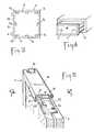
- each buffer 3 can be constituted, for example, by a hollow core 11 , made of an elastic material, such as rubber, and coated with a protective material 12 , such as silicone ( fig. 2 ).
- a protective material 12 such as silicone ( fig. 2 ).
- each pad is fixed to the support by a point of glue and is positioned so that the axis A of the core is parallel to the support and to the plate to ensure its function. pressure on the plate.
- pads 3 can be made in a different way to assume the functions described above, such as, for example, by a solid core made of an elastic material and coated with silicone.
- the buffers 3 are placed in proximity relation with respect to the edges b of the plate 1 , to assume their function of damping of shocks and vibrations.
- the position of the buffers along the edges b as well as their number are determined in relation to the type of panel and the intended application. Practical experience has shown that at least some of the buffers 3 must be placed in relation to the places on the support where contacts, shocks or vibrations are liable to appear.
- the panel advantageously comprises at least two buffers 31 placed in proximity relation to the corners of the plate delimited, in part, by the edge b1 situated opposite the edge 2 bord of the support bearing the hinges 4 ( fig. 3 ).
- the construction panel according to the invention is thus particularly suitable for forming mobile joinery which, by its function, is particularly subjected to shocks and vibrations.
- Figs. 5 and 6 illustrate an exemplary embodiment of a framing border 7 , specially designed to obtain and maintain a correct join of the profile segments, despite the forces exerted on the flange 8 , due to the weight of the decorative plate 1 .
- the framing border is formed of profiles 15 each having a cross section, generally in an "L" shape.
- Each profile 15 has a core 16 in which is formed a channel 17 intended to receive one of the branches of an assembly bracket 18 .
- the core of the profiles has a groove 19 , one of the sides of which extends at right angles to form the flange 8 for supporting the plate 1 .
- the other flank of the groove 19 constitutes an abutment face 21 whose function will be better understood in the description which follows.
- the core 16 has, on its face opposite the rim 8 , a groove for adapting the seal 6 .
- the framing border thus formed is designed to cooperate with clips 22 mounted at a distance from each other in complementary clearances 23 which are formed on the edge of the support 2 .
- Each clip 22 is fixed to the support 2 by screws 24 and comprises a lug 25 cut partially to form an elastic member.
- Each lug 25 has an inclined upper panel 26 favoring the engagement of the profiles until the lugs come to bear on the abutment face 21 and take place inside the groove 19 .
- the framing border thus formed, and in particular the clips 22 define, with the edge of the plate, a peripheral clearance J. Furthermore, the mounting of the border on the clips is allowed by the compression of the buffers 3 which exert, after assembly, a pressure necessary to keep the plate 1 in abutment on the flange 8 .
- the panel is equipped with a gripping element 28 ( fig. 1 and 6 )
- the rod 29 carries a buffer 3 intended to be placed between the plate 1 and the support 2 .
- the through hole 30 has a diameter in excess relative to that of the rod 29 , of a value at least equal to twice the peripheral play J , to allow any movement of the plate in the plane P.
- fig. 6 shows the plate 1 resting, by its lower edge, on the clips 22 , so that its upper edge defines, with the corresponding clips, a clearance equal to twice the peripheral clearance J already described.
Landscapes
- Engineering & Computer Science (AREA)
- Civil Engineering (AREA)
- Structural Engineering (AREA)
- Securing Of Glass Panes Or The Like (AREA)
- Finishing Walls (AREA)
Applications Claiming Priority (2)
| Application Number | Priority Date | Filing Date | Title |
|---|---|---|---|
| FR8715261 | 1987-11-02 | ||
| FR8715261A FR2622647B1 (fr) | 1987-11-02 | 1987-11-02 | Montage destine a l'habillage en granit, pierre ou marbre de panneaux fixes ou mobiles pour la realisation de meubles |
Publications (1)
| Publication Number | Publication Date |
|---|---|
| EP0316242A1 true EP0316242A1 (de) | 1989-05-17 |
Family
ID=9356461
Family Applications (1)
| Application Number | Title | Priority Date | Filing Date |
|---|---|---|---|
| EP88420370A Withdrawn EP0316242A1 (de) | 1987-11-02 | 1988-10-28 | Platte für die Konstruktion von Möbeln |
Country Status (2)
| Country | Link |
|---|---|
| EP (1) | EP0316242A1 (de) |
| FR (1) | FR2622647B1 (de) |
Cited By (4)
| Publication number | Priority date | Publication date | Assignee | Title |
|---|---|---|---|---|
| WO1992020260A1 (en) * | 1991-05-16 | 1992-11-26 | Ljungberg Karl Johan | Device for joining board-shaped elements into one unit |
| US6948788B1 (en) * | 2003-02-28 | 2005-09-27 | Hirsh Industries, Inc. | Removable drawer front, method of attachment and cabinet |
| US7665809B1 (en) * | 2007-07-23 | 2010-02-23 | Universal Furniture International, Inc. | Mirrored dresser storage system |
| IT201800008102A1 (it) * | 2018-08-16 | 2020-02-16 | Deal Srl | Dispositivo di rivestimento per ante ed ante così ottenute |
Citations (4)
| Publication number | Priority date | Publication date | Assignee | Title |
|---|---|---|---|---|
| CH487623A (de) * | 1968-09-28 | 1970-03-31 | Frawal Moebel Gmbh & Co Kg | Plattenförmiges Bauelement für Möbelfronten |
| GB1229984A (de) * | 1968-03-26 | 1971-04-28 | ||
| GB2079395A (en) * | 1980-06-27 | 1982-01-20 | British Aluminium Co Ltd | Clamp joint for panels |
| EP0151406A2 (de) * | 1984-02-08 | 1985-08-14 | Lothar Dallwitz | Möbel mit Tragteilen |
-
1987
- 1987-11-02 FR FR8715261A patent/FR2622647B1/fr not_active Expired - Fee Related
-
1988
- 1988-10-28 EP EP88420370A patent/EP0316242A1/de not_active Withdrawn
Patent Citations (4)
| Publication number | Priority date | Publication date | Assignee | Title |
|---|---|---|---|---|
| GB1229984A (de) * | 1968-03-26 | 1971-04-28 | ||
| CH487623A (de) * | 1968-09-28 | 1970-03-31 | Frawal Moebel Gmbh & Co Kg | Plattenförmiges Bauelement für Möbelfronten |
| GB2079395A (en) * | 1980-06-27 | 1982-01-20 | British Aluminium Co Ltd | Clamp joint for panels |
| EP0151406A2 (de) * | 1984-02-08 | 1985-08-14 | Lothar Dallwitz | Möbel mit Tragteilen |
Cited By (5)
| Publication number | Priority date | Publication date | Assignee | Title |
|---|---|---|---|---|
| WO1992020260A1 (en) * | 1991-05-16 | 1992-11-26 | Ljungberg Karl Johan | Device for joining board-shaped elements into one unit |
| US5480253A (en) * | 1991-05-16 | 1996-01-02 | Ljungberg; Karl-Johan | Device for joining board-shaped elements into one unit |
| US6948788B1 (en) * | 2003-02-28 | 2005-09-27 | Hirsh Industries, Inc. | Removable drawer front, method of attachment and cabinet |
| US7665809B1 (en) * | 2007-07-23 | 2010-02-23 | Universal Furniture International, Inc. | Mirrored dresser storage system |
| IT201800008102A1 (it) * | 2018-08-16 | 2020-02-16 | Deal Srl | Dispositivo di rivestimento per ante ed ante così ottenute |
Also Published As
| Publication number | Publication date |
|---|---|
| FR2622647A1 (fr) | 1989-05-05 |
| FR2622647B1 (fr) | 1990-02-09 |
Similar Documents
| Publication | Publication Date | Title |
|---|---|---|
| EP0340089B1 (de) | Verglasungselement für Vorhangfassaden | |
| CA1277347C (fr) | Ski | |
| EP1297237B1 (de) | Befestigungsvorrichtung für ein mehrschichtiges wandelement | |
| FR2857392A1 (fr) | Panneau d'isolation acoustique, notamment pour plafond, comportant une plaque de parement en platre perforee | |
| EP0161233A1 (de) | Dekoratives Paneel | |
| FR2764326A1 (fr) | Porte d'entree de local | |
| EP1106342A1 (de) | Verbundglasscheibe für eine Glasstruktur | |
| FR3078086A1 (fr) | Systeme de platelage comportant des moyens de fixation d'un bandeau peripherique vertical. | |
| WO2005017297A1 (fr) | Element feuillete en forme de plaque avec une fixation de position pour un assemblage colle | |
| EP1815098A1 (de) | Verbindungselemente zur Ausstattung von Platten, insbesondere Glasplatten, zur Befestigung sowie damit ausgestattete Platten | |
| EP2027354A1 (de) | Verbindungssysteme zum ausstatten von platten, insbesondere glasplatten, zu deren befestigung und damit ausgestattete platten | |
| FR2618656A3 (fr) | Element d'ameublement au moins partiellement en verre ou en materiau similaire avec profile d'appui en caoutchouc | |
| BE1010178A5 (fr) | Porte en verre structurel autoportant. | |
| FR2703101A1 (fr) | Bloc-porte à isolation phonique. | |
| EP1290963B1 (de) | Lagerungsvorrichtung für zwei Latten | |
| EP0887484B1 (de) | Fassade, insbesondere eine Glasfassade | |
| EP0408426B1 (de) | Wandverkleidungselement, bestehend aus einer Glas- und einer Metallplatte | |
| EP0633370B1 (de) | Gewölbtes Profil mit seitlichen Rillen für abdeckbare Bedachung | |
| FR2672918A1 (fr) | Element d'encadrement de plaque; notamment pour la realisation de parois de batiment. | |
| FR2721343A1 (fr) | Huisserie à profilés ouverts, équipée d'une garniture d'isolation. | |
| FR3020308B1 (fr) | Panneau sandwich comprenant deux couches d'absorption de deformations mecaniques | |
| EP0383656B1 (de) | Verkleidungselement oder Trennwand mit einem Blech | |
| FR2772884A1 (fr) | Panneau d'habillage adapte pour intercepter un flux de lumiere | |
| FR2742066A1 (fr) | Patin a roulettes ou a glace muni de moyens d'amortissement | |
| FR2546604A1 (fr) | Support formant console ou butee mobile, monte en appui et coulissant le long d'un profile |
Legal Events
| Date | Code | Title | Description |
|---|---|---|---|
| PUAI | Public reference made under article 153(3) epc to a published international application that has entered the european phase |
Free format text: ORIGINAL CODE: 0009012 |
|
| AK | Designated contracting states |
Kind code of ref document: A1 Designated state(s): AT BE CH DE ES FR GB GR IT LI LU NL SE |
|
| 17P | Request for examination filed |
Effective date: 19891002 |
|
| 17Q | First examination report despatched |
Effective date: 19901002 |
|
| STAA | Information on the status of an ep patent application or granted ep patent |
Free format text: STATUS: THE APPLICATION IS DEEMED TO BE WITHDRAWN |
|
| 18D | Application deemed to be withdrawn |
Effective date: 19910523 |