EP0316531A1 - Massenausgleichseinrichtung für Industrieroboter - Google Patents
Massenausgleichseinrichtung für Industrieroboter Download PDFInfo
- Publication number
- EP0316531A1 EP0316531A1 EP88114572A EP88114572A EP0316531A1 EP 0316531 A1 EP0316531 A1 EP 0316531A1 EP 88114572 A EP88114572 A EP 88114572A EP 88114572 A EP88114572 A EP 88114572A EP 0316531 A1 EP0316531 A1 EP 0316531A1
- Authority
- EP
- European Patent Office
- Prior art keywords
- arm
- balance mechanism
- spring
- balance
- robot
- Prior art date
- Legal status (The legal status is an assumption and is not a legal conclusion. Google has not performed a legal analysis and makes no representation as to the accuracy of the status listed.)
- Granted
Links
- 230000007246 mechanism Effects 0.000 title claims abstract description 52
- 230000008878 coupling Effects 0.000 claims abstract description 40
- 238000010168 coupling process Methods 0.000 claims abstract description 40
- 238000005859 coupling reaction Methods 0.000 claims abstract description 40
- 210000000707 wrist Anatomy 0.000 description 5
- 230000006835 compression Effects 0.000 description 3
- 238000007906 compression Methods 0.000 description 3
- 238000000034 method Methods 0.000 description 3
- 230000008859 change Effects 0.000 description 2
- 230000004048 modification Effects 0.000 description 2
- 238000012986 modification Methods 0.000 description 2
- 239000012141 concentrate Substances 0.000 description 1
- 238000009434 installation Methods 0.000 description 1
- 238000010422 painting Methods 0.000 description 1
- 230000004044 response Effects 0.000 description 1
- 238000003466 welding Methods 0.000 description 1
Images

Classifications
-
- B—PERFORMING OPERATIONS; TRANSPORTING
- B25—HAND TOOLS; PORTABLE POWER-DRIVEN TOOLS; MANIPULATORS
- B25J—MANIPULATORS; CHAMBERS PROVIDED WITH MANIPULATION DEVICES
- B25J3/00—Manipulators of leader-follower type, i.e. both controlling unit and controlled unit perform corresponding spatial movements
-
- B—PERFORMING OPERATIONS; TRANSPORTING
- B25—HAND TOOLS; PORTABLE POWER-DRIVEN TOOLS; MANIPULATORS
- B25J—MANIPULATORS; CHAMBERS PROVIDED WITH MANIPULATION DEVICES
- B25J19/00—Accessories fitted to manipulators, e.g. for monitoring, for viewing; Safety devices combined with or specially adapted for use in connection with manipulators
- B25J19/0008—Balancing devices
- B25J19/0016—Balancing devices using springs
-
- B—PERFORMING OPERATIONS; TRANSPORTING
- B25—HAND TOOLS; PORTABLE POWER-DRIVEN TOOLS; MANIPULATORS
- B25J—MANIPULATORS; CHAMBERS PROVIDED WITH MANIPULATION DEVICES
- B25J19/00—Accessories fitted to manipulators, e.g. for monitoring, for viewing; Safety devices combined with or specially adapted for use in connection with manipulators
Definitions
- the present invention relates to a balance mechanism for use in an industrial robot, an automatization apparatus and the like.
- An industrial robot is provided with a balance mechanism to take the balance of a plurality of arms.
- a playback type robot used for painting, welding and assembling is required to learn a movement procedure by moving the robot in the order of a working procedure by an operator. Accordingly, it is necessary to take the balance of the robot even if the arms are in any position in order to improve the performance of learning the working procedure.
- the balance mechanism having a simple structure uses a spring.
- the present applicant has proposed a balance mechanism by a spring using a link mechanism (referred to Japanese Utility Model Provisional Publication No. 61-144993, or No. 144993/1986).
- Fig. 6 is a front view of a robot including the above balance mechanism of a spring type
- Fig. 7 is a sectional view of the robot taken along line A-A
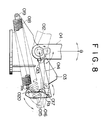
- Fig. 8 is a side view of the robot looking in the direction of arrow B.
- a rotatable stand 02 is rotatably mounted on a base 01 of the robot.
- a vertical arm 04 is swingably mounted to a bracket 03 attached on the rotatable stand 02 and a horizontal arm 05 is swingably mounted to an upper portion of the vertical arm 04.
- a wrist 06 is mounted to a tip of the horizontal arm 05 and the wrist 06 can be moved in plural directions.
- the horizontal arm 05 is adapted to be driven by an actuator 07 and the vertical arm 04 is also adapted to be driven by an actuator 08.
- Figs. 7 and 8 show the balance mechanism of the vertical arm 04.
- the vertical arm 04 is swingably supported to the bracket 03 on the rotatable stand 02 through a shaft 012.
- One end of a link 014 is rotatably coupled with a lower portion of the vertical arm 04 through a pin 013.
- a lever 016 is rotatably mounted to the bracket 03 through a pin 015.
- the other end of the link 014 is rotatably coupled with an upper end of the lever 016 through a pin 017.
- One end of a spring 018 is rotatably attached to an end of the bracket 03 opposite to the side to which the lever 016 is mounted and the other end of the spring 018 is coupled with a lower end of the lever 016 through a pin 020.
- the force applied to the vertical arm 04 is transmitted to the link 014 which is swingably coupled with a pin 013 being at a distance of r from the shaft 012 and further transmitted through the pin 017, the lever 016 and the pin 020 to the spring 018.
- the moment around the pin 015 is varied in response to variations of an angle between the link 014 and a line of the pins 015 and 017 and an angle between the spring 018 and a line of the pin 015 and 020 to obtain the balance force in reponse to a posture or positional state of the vertical arm 04 at all times.
- a balance mechanism of the horizontal arm 05 includes, as shown in Fig. 7, a link mechanism 022 and a spring 021 having an end swingably supported to a pin 019 in the same manner as the spring 018 used in the balance mechanism of the vertical arm 04.
- the structure of the link mechanism 022 is substantially identical with that of the vertical arm and accordingly description thereof is omitted.
- the two parallel springs 018 and 021 are mounted to the bracket 03 and the balance of the vertical and horizontal arms is adapted to be taken by both the springs 018 and 021 through the link mechanisms.
- the balance mechanism requires modification of many elements used therein such as, for example, the pin 013, link 014, lever 016, pin 015 and spring 018 when the robot is used by hanging or fixing it on a wall or by hanging it from a ceiling in addition to using the robot in the vertical state.
- the link mechanisms used in the balance mechanisms of both the horizontal and vertical arms require many parts.
- the present invention has been made in view of the above problems and an object thereof is to provide a balance mechanism for taking the balance of a robot exactly regardless of an installation position of the robot and without modification of elements of the balance mechanism and having a greatly reduced elements.
- a balance mechanism of an industrial robot comprises a first balance mechanism for a first arm swingably mounted to a stand of the industrial robot including a coupling member disposed in a rotary center of a proximal end of the first arm and being angularly moved in synchronism with the first arm, a coupling element mounted to an eccentric position to a center of the angular movement of the coupling member to be angularly moved in interlocked relationship with the coupling member, a spring having one end fixed to the stand, a flexible coupling device having one end fixed to the coupling element and the other end fixed to the other end of the spring and a guide for guiding the flexible coupling device to move the spring in a direction in which the spring is deformed when the first arm is angularly moved, and a second balance mechanism for a second arm swingably mounted to a distal end of the first arm including a counterbalancer disposed in the opposite side to an operation side of the second arm to keep the balance with the
- the coupling member In operation, when the first arm is angularly moved, the coupling member is angularly moved in synchronism with the angular movement of the first arm.
- the coupling member is coupled with the coupling element which is coupled with the flexible coupling device.
- the flexible coupling device is moved in the direction in which the spring is deformed through the guide to keep the balance of the first arm.
- the operation side of the second arm are balanced with the counterbalancer to keep the balance of the second arm.
- the balance mechanism of the industrial robot of the present invention takes the balance by operating the spring through the flexible coupling device without using the conventional link mechanism. Accordingly, the number of parts constituting the balance mechanism is greatly reduced and further the balance mechanism can be applied as it is without exchanging the parts largely even if the industrial robot is installed in any position.
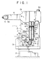
- Fig. 1 is a partially broken view of the balance mechanism provided in the industrial robot according to an embodiment of the present invention
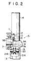
- Fig. 2 is a sectional view of a main portion of the balance mechanism of Fig. 1 in which a pin support is attached in a position of B2
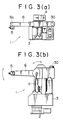
- Figs. 3(a) and (b) are a plan view and a front view of the industrial robot provided with the balance mechanism.
- the industrial robot (hereinafter referred to as "robot") 1 includes a rotatable stand (hereinafter referred to as "stand") 3 which is rotatably disposed on a base 2 through a bearing not shown.
- a proximal end of a first arm 4 is swingably mounted to the stand 3 and a second arm 6 provided with an operative wrist 5 mounted to one end of the second arm is swingably mounted to a distal end of the first arm 4.
- Actuators for driving the stand 3, the first arm 4 and the second arm 6 are not shown.
- the first arm 4 of which the proximal end is swingably mounted to the stand 3 and the second arm 6 mounted to the distal end of the first arm 4 are provided with a first balance mechanism Z1 and a second balance mechanism Z2 so that both of the arms keep the balance.
- the first balance mechanism Z1 provided in the first arm 4 is described in detail.
- the first balance mechanism Z1 provided in the first arm 4 comprises a coupling member including a coupling body 7 which is integrally mounted to a center ⁇ of angular movement of the proximal end of the first arm 4 mounted swingably to the stand 3 and a pin support 11, a compression spring (hereinafter referred to as "spring") 8 having one end fixed to the stand 3, a chain 9 constituting a flexible coupling device which transmits the angular movement of the arm 4 to the spring 8 through the coupling member continuously, and a guide constituted by sprockets 21A and 21B.
- the coupling body 7 is integrally disposed to the center ⁇ of the angular movement of the proximal end of the first arm 4 to be angularly moved in synchronism with the first arm 4.
- the pin support 11 including a pin 10 mounted vertically thereto is fixed to the coupling body 7 by means of a bolt not shown eccentrically to the center ⁇ of the angular movement of the first arm so that the mounting position of the pin support 11 can be changed.
- the coupling body 7 and the pin support 11 constitute the coupling member.
- a coupling element 13 is rotatably coupled with the pin 10 of the pin support 11 through a bearing 12.
- the spring 8 including one end 8a fixed to the stand is contained in a cover 14 which includes an opening 15 formed at a lower end thereof near the stand.
- a chain support 16 is mounted to the other end 8b of the spring 8 which is not fixed to the stand 3 of the spring 8.
- a chain support shaft 17 is mounted to the chain support 16 so that the vertical mounting position of the chain support 16 can be changed.
- the sprockets 21A and 21B are disposed side by side to a support shaft 20 disposed rotatably through a bearing 19 to the stand 3 to constitute the guide so that the sprockets are angularly moved in synchronism with each other.
- the other end of the chain 9A having one end mounted to the chain support shaft 17 is fixed to one dent 22A of the sprocket 21A. Further, the other end of the chain 9B having one end mounted to the coupling element 13 is fixed to one dent not shown of the sprocket 21B.
- the respective other end portions of both the chains 9A and 9B are wound on lower sides of the sprockets 21A and 21B, respectively, in the opposite direction to each other. A portion of the chain 9A from the start point of the engagement between the chain 9A and the sprocket 21A to the mounting position of the chain 9A to the chain support shaft 17 passes through the opening 15 of the cover 14 and extends straight.
- the deformation direction of the spring 8 is identical with the moving direction of the chain toward the sprocket 21A.
- a distance of the chain 9B between the start point of the engagement between the chain 9B and the sprocket 21B and the coupling point between the chain 9B and the coupling element 13 is minimized when the first arm 4 stands vertically. Accordingly, when the first arm 4 is angularly moved in the direction of arrow A1 or A2, the sprocket 21B angularly moved clockwise (in the direction of arrow A3 in Fig.
- the first balance mechanism Z1 is operated as follows.
- the position of the pin 10 when the load of the first arm 4 is varied greatly, the position of the pin 10, the position of the chain support shaft 17 with respect to the chain support 16, the diameter of the sprockets 21A and 21B concerning the chains 9A and 9B and the resilient force and the spring constant of the spring 8 may be varied to cope with the variation of the load.
- the second balance mechanism Z2 provided in the second arm 6 is described in detail.
- the operative wrist 5 is mounted to one end 6a of the second arm 6 mounted to the distal end of the first arm 4.
- a counterbalancer 30 is provided to the other end of the second arm 6 opposite to the end 6a while the center ⁇ of the angular movement of the second arm 6 constitutes a fulcrum.
- the second arm 6 is provided with the counterbalancer 30, the second arm 6 is adapted to balance with the counterbalancer 30 in the center ⁇ of the angular movement of the second arm 6 even if the second arm 6 is changed to any position.
- the load applied to the second arm 6 concentrates on the center ⁇ of the angular movement thereof and accordingly the load applied to the first arm 4 does not change even if the second arm 6 is moved to any position.
- the weight of the counterbalancer 30 can be varied and the balance of the second arm with respect to the center ⁇ of the angular movement thereof can be kept easily.
- the mounting position of the pin support 11 to the coupling body 7 of the balance mechanism Z1 for the first arm 4 changes from the position B1 to B2 shown in Fig. 1 while the spring 8 is compressed.
- the spring 8 is always compressed to take the balance in order to support the load of the first arm 4 and the second arm 6.
- the spring 8 is further compressed to support the load.
- the spring 8 is adapted to be reversely returned to take the balance.
- the chains 9A and 9B are used as the flexible coupling device, while the flexible coupling device may be a timing belt and a wire if it can change the moment continuously.
- the compression spring is suitable for the spring 8 in the balance mechanism of the present invention, while it is not necessarily limited to the compression spring.
- the coupling element 13 may be directly coupled with the chain support shaft 17 through one chain and the chain guide may constitute one sprocket.
Landscapes
- Engineering & Computer Science (AREA)
- Robotics (AREA)
- Mechanical Engineering (AREA)
- Manipulator (AREA)
Applications Claiming Priority (2)
| Application Number | Priority Date | Filing Date | Title |
|---|---|---|---|
| JP288347/87 | 1987-11-17 | ||
| JP62288347A JP2538953B2 (ja) | 1987-11-17 | 1987-11-17 | 工業用ロボットのバランス機構 |
Publications (2)
| Publication Number | Publication Date |
|---|---|
| EP0316531A1 true EP0316531A1 (de) | 1989-05-24 |
| EP0316531B1 EP0316531B1 (de) | 1993-11-10 |
Family
ID=17729028
Family Applications (1)
| Application Number | Title | Priority Date | Filing Date |
|---|---|---|---|
| EP88114572A Expired - Lifetime EP0316531B1 (de) | 1987-11-17 | 1988-09-07 | Massenausgleichseinrichtung für Industrieroboter |
Country Status (9)
| Country | Link |
|---|---|
| US (1) | US4954043A (de) |
| EP (1) | EP0316531B1 (de) |
| JP (1) | JP2538953B2 (de) |
| KR (1) | KR930007257B1 (de) |
| CN (1) | CN1012485B (de) |
| AU (1) | AU596317B2 (de) |
| CA (1) | CA1304766C (de) |
| DE (1) | DE3885570T2 (de) |
| MY (1) | MY103344A (de) |
Cited By (1)
| Publication number | Priority date | Publication date | Assignee | Title |
|---|---|---|---|---|
| WO1992005016A1 (en) * | 1990-09-14 | 1992-04-02 | The Trustees Of The University Of Pennsylvania | Methods and apparatus for passively compensating for the effects of gravity upon articulated structures |
Families Citing this family (33)
| Publication number | Priority date | Publication date | Assignee | Title |
|---|---|---|---|---|
| DE3884800D1 (de) * | 1987-05-27 | 1993-11-11 | Schloendorff Georg Prof Dr | Verfahren und vorrichtung zur reproduzierbaren optischen darstellung eines chirurgischen eingriffes. |
| US5211548A (en) * | 1989-07-31 | 1993-05-18 | Terumo Kabushiki Kaisha | Peristaltic pump having a motor overload protector |
| US6405072B1 (en) | 1991-01-28 | 2002-06-11 | Sherwood Services Ag | Apparatus and method for determining a location of an anatomical target with reference to a medical apparatus |
| US5662111A (en) | 1991-01-28 | 1997-09-02 | Cosman; Eric R. | Process of stereotactic optical navigation |
| US6006126A (en) * | 1991-01-28 | 1999-12-21 | Cosman; Eric R. | System and method for stereotactic registration of image scan data |
| US6675040B1 (en) | 1991-01-28 | 2004-01-06 | Sherwood Services Ag | Optical object tracking system |
| US5603318A (en) | 1992-04-21 | 1997-02-18 | University Of Utah Research Foundation | Apparatus and method for photogrammetric surgical localization |
| EP0997109B1 (de) | 1993-04-26 | 2003-06-18 | ST. Louis University | Anzeige der Lage einer chirurgischen Sonde |
| US6354167B1 (en) | 2000-06-26 | 2002-03-12 | The United States Of America As Represented By The Secretary Of The Navy | Scara type robot with counterbalanced arms |
| ITBO20000529A1 (it) * | 2000-09-13 | 2002-03-13 | Jobs Spa | Macchina utensile |
| GB0222522D0 (en) | 2002-09-27 | 2002-11-06 | Controlled Therapeutics Sct | Water-swellable polymers |
| GB0417401D0 (en) | 2004-08-05 | 2004-09-08 | Controlled Therapeutics Sct | Stabilised prostaglandin composition |
| DE102005013014A1 (de) * | 2005-03-21 | 2006-10-05 | Dürr Systems GmbH | Beschichtungsanlage und zugehöriges Verfahren |
| DE102005033972A1 (de) * | 2005-07-20 | 2007-01-25 | Dürr Systems GmbH | Beschichtungsverfahren und zugehörige Beschichtungseinrichtung |
| DE102006020886A1 (de) * | 2006-05-05 | 2007-11-08 | Kuka Roboter Gmbh | Roboter |
| GB0613333D0 (en) | 2006-07-05 | 2006-08-16 | Controlled Therapeutics Sct | Hydrophilic polyurethane compositions |
| GB0613638D0 (en) | 2006-07-08 | 2006-08-16 | Controlled Therapeutics Sct | Polyurethane elastomers |
| AU2007274081B2 (en) * | 2006-07-12 | 2012-08-02 | Controlled Therapeutics (Scotland) Ltd. | Drug delivery polymer with hydrochloride salt of clindamycin |
| EP1905551B1 (de) * | 2006-09-27 | 2010-02-24 | Abb Ab | Industrieroboter mit Druckluftzufuhr in Gewichtsausgleichsvorrichtung |
| GB0620685D0 (en) | 2006-10-18 | 2006-11-29 | Controlled Therapeutics Sct | Bioresorbable polymers |
| CN101190769B (zh) * | 2006-12-01 | 2010-05-26 | 上海比亚迪有限公司 | 重载荷平衡机构 |
| CN102990677A (zh) * | 2011-09-13 | 2013-03-27 | 鸿富锦精密工业(深圳)有限公司 | 平衡机构及应用该平衡机构的机器人 |
| JP2016030315A (ja) * | 2014-07-29 | 2016-03-07 | 株式会社安川電機 | ロボット |
| CN104526716B (zh) * | 2014-12-17 | 2016-07-06 | 上海交通大学 | 一种工业机器人储能节能型重力平衡装置 |
| CN105108777A (zh) * | 2015-10-14 | 2015-12-02 | 南京埃斯顿机器人工程有限公司 | 工业机器人第二关节平衡机构 |
| CN107081786A (zh) * | 2016-02-14 | 2017-08-22 | 范红兵 | 一种机器人臂助力装置 |
| CN106078724B (zh) * | 2016-06-29 | 2020-01-24 | 微创(上海)医疗机器人有限公司 | 机械臂及其手术机器人 |
| CN106151428B (zh) * | 2016-08-01 | 2018-10-30 | 江门市众能电控科技有限公司 | 一种弹性支承的竖向摆臂机构 |
| JP6889826B2 (ja) * | 2018-11-16 | 2021-06-18 | 株式会社安川電機 | ロボット |
| CA3128150A1 (en) | 2019-01-31 | 2020-08-06 | American Sterilizer Company | Support arm for medical device support system |
| EP4419040B1 (de) | 2021-10-18 | 2025-06-18 | American Sterilizer Company | Lastausgleichsarm für stützsystem für medizinische vorrichtungen |
| CN114055447A (zh) * | 2021-11-29 | 2022-02-18 | 彭丽 | 一种基于柔性牵引方式的摆臂消重力平衡方法 |
| KR102685669B1 (ko) * | 2024-05-31 | 2024-07-16 | 주식회사 유일로보틱스 | 수평 이동 가능한 7축 다관절 로봇 |
Citations (3)
| Publication number | Priority date | Publication date | Assignee | Title |
|---|---|---|---|---|
| EP0044737A2 (de) * | 1980-07-19 | 1982-01-27 | Shin Meiwa Industry Co., Ltd. | Gelenk-Roboter |
| EP0169318A1 (de) * | 1984-05-21 | 1986-01-29 | Unimation Inc. | Roboter |
| EP0218075A1 (de) * | 1985-09-10 | 1987-04-15 | Siemens Aktiengesellschaft | Gelenkroboter |
Family Cites Families (19)
| Publication number | Priority date | Publication date | Assignee | Title |
|---|---|---|---|---|
| DE219427C (de) * | ||||
| SE409184B (sv) * | 1977-12-01 | 1979-08-06 | Hiab Foco Ab | Med styrsystem forsedd industrirobot |
| SU715317A1 (ru) * | 1978-08-14 | 1980-02-15 | Московское Ордена Ленина И Ордена Трудового Красного Знамени Высшее Техническое Училище Им.Н.Э.Баумана | Рука манипул тора |
| JPS56119391A (en) * | 1980-02-25 | 1981-09-18 | Shin Meiwa Ind Co Ltd | Weight equalizer for rotary arm |
| AU7401881A (en) * | 1980-08-15 | 1982-02-18 | Dainichi Kiko K.K. | Robot |
| US4500251A (en) * | 1982-02-05 | 1985-02-19 | Mitsubishi Denki Kabushiki Kaisha | Multijoint manipulator |
| SU1074709A1 (ru) * | 1982-08-11 | 1984-02-23 | Научно-Исследовательский И Конструкторско-Технологический Институт Теплоэнергетического Приборостроения | Механическа рука |
| JPS5937077A (ja) * | 1982-08-24 | 1984-02-29 | 株式会社ダイフク | 関節型ロボツトの駆動機構 |
| JPS59112587A (ja) * | 1982-12-17 | 1984-06-29 | 松下電器産業株式会社 | 同軸ケーブル用コネクター |
| JPS60131182A (ja) * | 1983-12-20 | 1985-07-12 | 松下電器産業株式会社 | 産業用ロボツトのバランス装置 |
| DE3421302A1 (de) * | 1984-06-08 | 1985-12-12 | Hoechst Ag, 6230 Frankfurt | Verfahren zur isolierung und reinigung von (alpha)-interferonen |
| JPS6114879A (ja) * | 1984-06-29 | 1986-01-23 | フアナツク株式会社 | 産業用ロボツトの上腕重力バランサ機構 |
| US4659280A (en) * | 1985-01-22 | 1987-04-21 | Gmf Robotics Corporation | Robot with balancing mechanism having a variable counterbalance force |
| JPS61197176A (ja) * | 1985-02-26 | 1986-09-01 | 三菱重工業株式会社 | マニピユレ−タ |
| JPS61144993U (de) * | 1985-03-01 | 1986-09-06 | ||
| JPS6257891A (ja) * | 1985-09-05 | 1987-03-13 | フアナツク株式会社 | 関節型工業用ロボツトのバランサ機構 |
| JPS637918A (ja) * | 1986-06-27 | 1988-01-13 | Matsushita Electric Ind Co Ltd | スライドコア作動遅延装置 |
| US4753128A (en) * | 1987-03-09 | 1988-06-28 | Gmf Robotics Corporation | Robot with spring pivot balancing mechanism |
| US4784010A (en) * | 1987-04-27 | 1988-11-15 | Graco Robotics Inc. | Electric robotic work unit |
-
1987
- 1987-11-17 JP JP62288347A patent/JP2538953B2/ja not_active Expired - Lifetime
-
1988
- 1988-08-09 AU AU20538/88A patent/AU596317B2/en not_active Ceased
- 1988-08-11 MY MYPI88000922A patent/MY103344A/en unknown
- 1988-08-24 CA CA000575541A patent/CA1304766C/en not_active Expired - Lifetime
- 1988-09-07 EP EP88114572A patent/EP0316531B1/de not_active Expired - Lifetime
- 1988-09-07 DE DE3885570T patent/DE3885570T2/de not_active Expired - Fee Related
- 1988-11-15 KR KR1019880015011A patent/KR930007257B1/ko not_active Expired - Fee Related
- 1988-11-17 CN CN88107904A patent/CN1012485B/zh not_active Expired
-
1990
- 1990-02-07 US US07/477,114 patent/US4954043A/en not_active Expired - Fee Related
Patent Citations (3)
| Publication number | Priority date | Publication date | Assignee | Title |
|---|---|---|---|---|
| EP0044737A2 (de) * | 1980-07-19 | 1982-01-27 | Shin Meiwa Industry Co., Ltd. | Gelenk-Roboter |
| EP0169318A1 (de) * | 1984-05-21 | 1986-01-29 | Unimation Inc. | Roboter |
| EP0218075A1 (de) * | 1985-09-10 | 1987-04-15 | Siemens Aktiengesellschaft | Gelenkroboter |
Non-Patent Citations (1)
| Title |
|---|
| SOVIET INVENTIONS ILLUSTRATED, week C39, class P62, 8th November 1980, no. J4519 C/39, Derwent Publications Ltd, London, GB; & SU-A-715 317 (MOSCOW BAUMAN TECH. COLL.) 14-08-1978 * |
Cited By (1)
| Publication number | Priority date | Publication date | Assignee | Title |
|---|---|---|---|---|
| WO1992005016A1 (en) * | 1990-09-14 | 1992-04-02 | The Trustees Of The University Of Pennsylvania | Methods and apparatus for passively compensating for the effects of gravity upon articulated structures |
Also Published As
| Publication number | Publication date |
|---|---|
| DE3885570T2 (de) | 1994-05-26 |
| AU596317B2 (en) | 1990-04-26 |
| KR890007853A (ko) | 1989-07-06 |
| JPH01135488A (ja) | 1989-05-29 |
| KR930007257B1 (ko) | 1993-08-04 |
| CA1304766C (en) | 1992-07-07 |
| CN1033253A (zh) | 1989-06-07 |
| JP2538953B2 (ja) | 1996-10-02 |
| US4954043A (en) | 1990-09-04 |
| DE3885570D1 (de) | 1993-12-16 |
| EP0316531B1 (de) | 1993-11-10 |
| CN1012485B (zh) | 1991-05-01 |
| MY103344A (en) | 1993-05-29 |
| AU2053888A (en) | 1989-05-18 |
Similar Documents
| Publication | Publication Date | Title |
|---|---|---|
| EP0316531A1 (de) | Massenausgleichseinrichtung für Industrieroboter | |
| EP0249318B1 (de) | Handhabungsgerät | |
| EP0102082B1 (de) | Industrieroboter | |
| JPH05253885A (ja) | ロボットアームのバランサ装置 | |
| US5132601A (en) | Industrial robot | |
| US8899125B2 (en) | Counterbalance assembly | |
| JP3614383B2 (ja) | ロボット | |
| US5673595A (en) | Four degree-of-freedom manipulator | |
| JP2003181789A (ja) | 機械的自重補償装置 | |
| EP1863734A2 (de) | Parallelroboter | |
| US11708882B2 (en) | Head mechanism and robot | |
| WO2019074296A1 (ko) | 로봇 핸드 | |
| US4803895A (en) | Balancing mechanism | |
| CN208788595U (zh) | 一种视觉定位机器人 | |
| KR20210010751A (ko) | 중력보상장치가 적용된 수동형 다자유도 링키지 유닛 및 이를 포함하는 로봇 교시 시스템 | |
| KR20120128876A (ko) | 중력 보상 기능을 가지는 햅틱 장치 | |
| KR960008259B1 (ko) | 로보트의 중력토크 보상용 중력 밸런서 | |
| EP0169473B1 (de) | Manipulator-Antriebssystem | |
| KR100434771B1 (ko) | 다관절 로보트의 발란서 | |
| SU1194668A1 (ru) | Звено-модуль руки манипул тора | |
| JPH1158287A (ja) | ロボットのためのバランス装置 | |
| SU1371899A1 (ru) | Манипул тор | |
| SU1324984A1 (ru) | Грузозахватное устройство | |
| SU1407791A1 (ru) | Промышленный робот | |
| WO2026048953A1 (ja) | 重力補償装置、及びマニピュレーター |
Legal Events
| Date | Code | Title | Description |
|---|---|---|---|
| PUAI | Public reference made under article 153(3) epc to a published international application that has entered the european phase |
Free format text: ORIGINAL CODE: 0009012 |
|
| AK | Designated contracting states |
Kind code of ref document: A1 Designated state(s): DE FR GB IT |
|
| 17P | Request for examination filed |
Effective date: 19890830 |
|
| 17Q | First examination report despatched |
Effective date: 19901217 |
|
| GRAA | (expected) grant |
Free format text: ORIGINAL CODE: 0009210 |
|
| AK | Designated contracting states |
Kind code of ref document: B1 Designated state(s): DE FR GB IT |
|
| REF | Corresponds to: |
Ref document number: 3885570 Country of ref document: DE Date of ref document: 19931216 |
|
| ET | Fr: translation filed | ||
| ITF | It: translation for a ep patent filed | ||
| PLBE | No opposition filed within time limit |
Free format text: ORIGINAL CODE: 0009261 |
|
| STAA | Information on the status of an ep patent application or granted ep patent |
Free format text: STATUS: NO OPPOSITION FILED WITHIN TIME LIMIT |
|
| 26N | No opposition filed | ||
| PGFP | Annual fee paid to national office [announced via postgrant information from national office to epo] |
Ref country code: GB Payment date: 20010905 Year of fee payment: 14 |
|
| PGFP | Annual fee paid to national office [announced via postgrant information from national office to epo] |
Ref country code: FR Payment date: 20010911 Year of fee payment: 14 |
|
| PGFP | Annual fee paid to national office [announced via postgrant information from national office to epo] |
Ref country code: DE Payment date: 20010924 Year of fee payment: 14 |
|
| REG | Reference to a national code |
Ref country code: GB Ref legal event code: IF02 |
|
| PG25 | Lapsed in a contracting state [announced via postgrant information from national office to epo] |
Ref country code: GB Free format text: LAPSE BECAUSE OF NON-PAYMENT OF DUE FEES Effective date: 20020907 |
|
| PG25 | Lapsed in a contracting state [announced via postgrant information from national office to epo] |
Ref country code: DE Free format text: LAPSE BECAUSE OF NON-PAYMENT OF DUE FEES Effective date: 20030401 |
|
| GBPC | Gb: european patent ceased through non-payment of renewal fee |
Effective date: 20020907 |
|
| PG25 | Lapsed in a contracting state [announced via postgrant information from national office to epo] |
Ref country code: FR Free format text: LAPSE BECAUSE OF NON-PAYMENT OF DUE FEES Effective date: 20030603 |
|
| REG | Reference to a national code |
Ref country code: FR Ref legal event code: ST |
|
| PG25 | Lapsed in a contracting state [announced via postgrant information from national office to epo] |
Ref country code: IT Free format text: LAPSE BECAUSE OF NON-PAYMENT OF DUE FEES Effective date: 20050907 |