EP0316625A2 - Lichtelektrische Positionsmesseinrichtung - Google Patents
Lichtelektrische Positionsmesseinrichtung Download PDFInfo
- Publication number
- EP0316625A2 EP0316625A2 EP88117788A EP88117788A EP0316625A2 EP 0316625 A2 EP0316625 A2 EP 0316625A2 EP 88117788 A EP88117788 A EP 88117788A EP 88117788 A EP88117788 A EP 88117788A EP 0316625 A2 EP0316625 A2 EP 0316625A2
- Authority
- EP
- European Patent Office
- Prior art keywords
- scanning unit
- stationary
- ae1b
- scanning
- movable
- Prior art date
- Legal status (The legal status is an assumption and is not a legal conclusion. Google has not performed a legal analysis and makes no representation as to the accuracy of the status listed.)
- Granted
Links
Images
Classifications
-
- G—PHYSICS
- G01—MEASURING; TESTING
- G01D—MEASURING NOT SPECIALLY ADAPTED FOR A SPECIFIC VARIABLE; ARRANGEMENTS FOR MEASURING TWO OR MORE VARIABLES NOT COVERED IN A SINGLE OTHER SUBCLASS; TARIFF METERING APPARATUS; MEASURING OR TESTING NOT OTHERWISE PROVIDED FOR
- G01D5/00—Mechanical means for transferring the output of a sensing member; Means for converting the output of a sensing member to another variable where the form or nature of the sensing member does not constrain the means for converting; Transducers not specially adapted for a specific variable
- G01D5/26—Mechanical means for transferring the output of a sensing member; Means for converting the output of a sensing member to another variable where the form or nature of the sensing member does not constrain the means for converting; Transducers not specially adapted for a specific variable characterised by optical transfer means, i.e. using infrared, visible, or ultraviolet light
- G01D5/32—Mechanical means for transferring the output of a sensing member; Means for converting the output of a sensing member to another variable where the form or nature of the sensing member does not constrain the means for converting; Transducers not specially adapted for a specific variable characterised by optical transfer means, i.e. using infrared, visible, or ultraviolet light with attenuation or whole or partial obturation of beams of light
- G01D5/34—Mechanical means for transferring the output of a sensing member; Means for converting the output of a sensing member to another variable where the form or nature of the sensing member does not constrain the means for converting; Transducers not specially adapted for a specific variable characterised by optical transfer means, i.e. using infrared, visible, or ultraviolet light with attenuation or whole or partial obturation of beams of light the beams of light being detected by photocells
- G01D5/347—Mechanical means for transferring the output of a sensing member; Means for converting the output of a sensing member to another variable where the form or nature of the sensing member does not constrain the means for converting; Transducers not specially adapted for a specific variable characterised by optical transfer means, i.e. using infrared, visible, or ultraviolet light with attenuation or whole or partial obturation of beams of light the beams of light being detected by photocells using displacement encoding scales
- G01D5/34707—Scales; Discs, e.g. fixation, fabrication, compensation
- G01D5/34715—Scale reading or illumination devices
Definitions
- the invention relates to a photoelectric position measuring device according to the preamble of claim 1.
- Such position measuring devices are used in particular in machine tools for measuring the relative position of a tool with respect to a workpiece to be machined, and in coordinate measuring machines for determining the position and / or dimensions of test objects.
- a length measuring device for measuring the relative position of two objects in the form of a movable carriage and the stationary bed of a processing machine.
- a graduation carrier with a graduation is accommodated in a housing which is attached to the machine bed.
- a scanning device scans the division of the graduation carrier to generate periodic scanning signals and is connected to the machine slide via a driver.
- the scanner is also an electrical Cable connected to a stationary evaluation device, in which measured values for the relative position of the machine slide with respect to the machine bed are formed from the periodic scanning signals.
- this length measuring device has the disadvantage that the electrical cable between the movable scanning device and the stationary evaluation device must be relatively long depending on the respective measuring length, so that damage to the cable cannot be ruled out.
- the coupling of electrical interference signals into the individual lines of this electrical cable can result in measurement errors, so that complex shielding of the electrical cable is necessary.
- the invention has for its object to rule out inaccuracies in the photo-electric position measuring device of the type mentioned by interference, in particular electrical, mechanical and thermal, and to achieve a more compact design of the measuring device.
- the advantages achieved by the invention consist in particular in that, by separating the scanning device into a movable scanning unit and into a stationary scanning unit, the latter can be connected to the stationary evaluation device via an electrical and / or optical cable of minimal length.
- This cable can be laid firmly and concealed so that it can no longer be damaged during machining operations; a metal protective hose for this cable can ent fall.
- a shielding of the cable against coupling of electrical interference pulses is no longer necessary due to the short length and the concealed laying of this cable. Since the movable scanning unit no longer has any electrical and heat-generating components, it is less susceptible to faults and is also lighter, cheaper and more compact in size. Overall, this results in a simpler, more cost-effective position measuring device with high measuring accuracy.
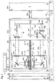
- FIG. 1 shows a side view of a first photoelectric incremental length measuring device for measuring the relative position of two objects S1, B1 which are movable in the measuring direction X; the movable object S1 is formed by a carriage and the stationary object B1 by the bed of a processing machine, not shown.
- a housing G1 in the form of a hollow profile is fastened to the stationary object B1 at both ends G1a, G1b by means of screws, not shown.
- a division carrier TT1 with an incremental division T1 is arranged on a web ST1 by means of an elastic adhesive layer KS1.
- a scanning device A1 which consists of a movable scanning unit AE1a and a stationary scanning unit AE1b.
- the movable scanning unit AE1a is connected to the movable object S1 via a carrier MT1 and can be displaced in the interior of the housing G1 in the measuring direction X along the graduation carrier TT1 parallel to the incremental graduation T1.
- the stationary scanning unit AE1b is also connected via an electrical cable KB1 to a stationary evaluation device AW1, which is also attached to the stationary object B1.
- a light-emitting diode LD In the interior of the stationary scanning unit AE1b, a light-emitting diode LD generates a light beam LB1a, which is directed in parallel by a collimator K; the light emitting diode LD and the collimator K form a lighting unit BE.
- the parallel light beam LB1 a of the stationary scanning unit AE1b passes through the interior of the housing G1 parallel to the measuring direction X and passes through one first condenser KDa into the movable scanning unit AE1a.
- the light beam LB1a is deflected perpendicularly to the measuring direction X by a first deflecting mirror US1a, directed parallel by a second condenser KDb and passes through the division T1 of the graduation carrier TT1 and subsequently two scanning divisions ATa, ATb of a scanning plate AP of the movable scanning unit AE1a.
- the two scanning divisions ATa, ATb are arranged next to one another in the measuring direction X and have the same period length as the division T1 of the division carrier TT1; however, the two scanning divisions ATa, ATb are offset from one another in the measuring direction X by a quarter of the period length and each have a polarizing film PFa, PFb with an orthogonal polarizing effect.
- the parallel light beam LB1 a is converted by the division T1 of the division carrier TT1 and by the two scanning divisions ATa, ATb together with the two polarizing foils PFa, PFb into a parallel modulated light beam LB1b with two halves polarized orthogonally to one another.
- the modulated, polarized light beam LB1b falls through a third condenser KDc, is deflected again parallel to the measuring direction X by a second deflecting mirror US1b, passes through the interior of the housing G1 parallel to the measuring direction X and after passing through a fourth condenser KDd of the movable scanning unit AE1a is separated by a divider prism TP in the stationary scanning unit AE1b into two partial beams TB1a, TB1b with mutually orthogonal polarization.
- the two Separated partial beams TB1a, TB1b each fall through a converging lens La, Lb onto an assigned photo element P1a, P1b in the stationary scanning unit Ae1b.
- the two photo elements P1a, P1b During the measuring movement of the movable scanning unit Ae1a with respect to the stationary object B1, the two photo elements P1a, P1b generate two periodic analog scanning signals S1a, S1b, which, according to the offset of the two scanning divisions ATa, ATb, are 90 ° out of phase with each other by a quarter of the period length in the measuring direction X. are; This phase shift allows the measuring movement to be discriminated in the positive or negative measuring direction X.
- the two scanning signals S1a, S1b transmitted to the evaluation device AW1 by means of two signal lines SLa, SLb via the electrical cable KB1 become measured values for the relative position of the movable in a known, not shown manner Object S1 obtained with respect to the stationary object B1, which can be displayed in digital form.
- the light-emitting diode LD of the lighting unit BE is supplied with power from a current source (not shown) in the evaluation device AW1 by means of two supply lines VL1a, VL1b via the electrical cable KB1.
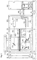
- FIG. 2 shows a side view of a second photoelectric incremental length measuring device for measuring the relative position of two objects S2, B2 which are movable in the measuring direction X; the movable object S2 are formed by a carriage and the stationary object B2 by the bed of a processing machine, not shown.
- a housing G2 in the form of a hollow profile is fastened at both ends G2a, G2b by means of screws, not shown.
- a division carrier TT2 with an incremental division T2 in the form of a phase grating is arranged on a web ST2 by means of an elastic adhesive layer KS2.
- a scanning device A2 which consists of a movable scanning unit AE2a and a stationary scanning unit AE2b.
- the movable scanning unit AE2a is connected to the movable object S2 via a driver MT2 and can be displaced in the interior of the housing G2 in the measuring direction X along the division carrier TT2 parallel to the incremental division T2.
- the stationary scanning unit AE2b is closed by the stationary scanning unit AE2b; this stationary scanning unit AE2b is thus firmly connected to the stationary object B2.
- the stationary scanning unit AE2b is also connected via a cable KB2 to a stationary evaluation device AW2, which is also attached to the stationary object B2.
- a laser LS generates a light beam LB2a as the illumination unit.
- the parallel light beam LB2a of the stationary scanning unit AE2b passes through the interior of the housing G2 parallel to the measuring direction X, becomes vertical in the movable scanning unit AE2a by a first deflecting mirror US2a deflected to the measuring direction X and passes through the division T2 of the division carrier TT2 in the form of the phase grating; the phase grating diffracts the incident light beam LB2a into a positive first-order diffraction beam BBa and into a negative first-order diffraction beam BBb.
- the negative diffraction beam BBb is deflected parallel to the measuring direction X by a second deflecting mirror US2b and interferes with the positive diffraction beam BBa in a division layer TS.
- the first partial beam bundle TB2a emanating from the sub-layer TS runs parallel to the measuring direction X, while the second partial beam bundle TB2b emanating from the sub-layer TS is likewise deflected parallel to the measuring direction X by a third deflecting mirror US2c.
- the two parallel partial beam bundles TB2a, TB2b pass through the interior of the housing G2 parallel to the measuring direction X and enter in the stationary scanning unit AE2b each in an associated optical waveguide LWa, LWb, which connect the stationary scanning unit AE2b to the stationary evaluation device AW2.
- the two partial light beams TB2a, TB2b transmitted by the two optical fibers LWa, LWb of the cable KB2 act on assigned photo elements P2a, P2b, which generate two periodic analog scanning signals S2a, S2b with a mutual phase shift of 180 °, from which, in turn, the The aforementioned manner, measured values for the relative position of the movable object S2 with respect to the stationary object B2 can be obtained, which can be displayed in digital form.
- the laser LS is powered by a current source, not shown, in the evaluation device AW2 by means of two supply lines VL2a, VL2b via the cable KB2.
- the stationary scanning units AE1b, AE2b can also be integrated in the associated evaluation devices AW1, AW2.
- the invention can be used successfully with incremental or absolute photoelectric length or angle measuring devices both on the transmitted light measurement principle and on the incident light measurement principle.
Landscapes
- Physics & Mathematics (AREA)
- General Physics & Mathematics (AREA)
- Length Measuring Devices By Optical Means (AREA)
- Control Of Electric Motors In General (AREA)
- Electrical Discharge Machining, Electrochemical Machining, And Combined Machining (AREA)
- Vehicle Body Suspensions (AREA)
- Machine Tool Sensing Apparatuses (AREA)
Abstract
Description
- Die Erfindung betrifft eine lichtelektrische Positionsmeßeinrichtung gemäß dem Oberbegriff des Anspruches 1.
- Derartige Positionsmeßeinrichtungen werden insbesondere bei Bearbeitungsmaschinen zum Messen der Relativlage eines Werkzeugs bezüglich eines zu bearbeitenden Werkstücks sowie bei Koordinatenmeßmaschinen zur Ermittlung von Lage und/oder Abmessungen von Prüfobjekten eingesetzt.
- Aus der DE-AS 26 30 880 ist eine Längenmeßeinrichtung zum Messen der Relativlage zweier Objekte in Form eines beweglichen Schlittens und des stationären Betts einer Bearbeitungsmaschine bekannt. Ein Teilungsträger mit einer Teilung ist in einem Gehäuse untergebracht, das am Maschinenbett befestigt ist. Im Gehäuse tastet eine Abtasteinrichtung die Teilung des Teilungsträgers zur Erzeugung von periodischen Abtastsignalen ab und ist über einen Mitnehmer mit dem Maschinenschlitten verbunden. Die Abtasteinrichtung ist ferner über ein elektrisches Kabel mit einer stationären Auswerteeinrichtung verbunden, in der aus den periodischen Abtastsignalen Meßwerte für die Relativlage des Maschinenschlittens bezüglich des Maschinenbetts gebildet werden. Diese Längenmeßeinrichtung weist jedoch den Nachteil auf, daß das elektrische Kabel zwischen der beweglichen Abtasteinrichtung und der stationären Auswerteeinrichtung in Abhängigkeit von der jeweiligen Meßlänge relativ lang sein muß, so daß eine Beschädigung des Kabels nicht ausgeschlossen werden kann. Weiterhin kann die Einkopplung von elektrischen Störsignalen in die einzelnen Leitungen dieses elektrischen Kabels Meßfehler zur Folge haben, so daß eine aufwendige Abschirmung des elektrischen Kabels erforderlich ist.
- Der Erfindung liegt die Aufgabe zugrunde, bei einer lichtelektrischen Positionsmeßeinrichtung der genannten Gattung Meßungenauigkeiten durch Störeinflüsse, insbesondere elektrischer und mechanischer sowie thermischer Art, auszuschließen und eine kompaktere Bauform der Meßeinrichtung zu erzielen.
- Diese Aufgabe wird erfindungsgemäß durch die kennzeichnenden Merkmale des Anspruchs 1 gelöst.
- Die mit der Erfindung erzielten Vorteile bestehen insbesondere darin, daß durch die Auftrennung der Abtasteinrichtung in eine bewegliche Abtasteinheit und in eine stationäre Abtasteinheit die letztere mit der stationären Auswerteeinrichtung über ein elektrisches und/oder optisches Kabel mit minimaler Länge verbunden werden kann. Dieses Kabel kann fest und verdeckt verlegt werden, so daß eine Beschädigung desselben bei Bearbeitungsvorgängen nicht mehr auftreten kann; ein Metallschutzschlauch für dieses Kabel kann somit ent fallen. Eine Abschirmung des Kabels gegen eine Einkopplung von elektrischen Störimpulsen ist wegen der kurzen Baulänge und der verdeckten Verlegung dieses Kabels nicht mehr erforderlich. Da die bewegliche Abtasteinheit keine elektrischen und wärmeerzeugenden Komponenten mehr aufweist, ist sie störunanfälliger und zudem leichter, billiger und kompakter in den Abmessungen. Insgesamt ergibt sich somit eine einfacher aufgebaute und preiswertere Positionsmeßeinrichtung hoher Meßgenauigkeit.
- Vorteilhafte Ausbildungen der Erfindung entnimmt man den Unteransprüchen.
- Ausführungsbeispiele der Erfindung werden anhand der Zeichnung näher erläutert.
- Es zeigen:
- Figur 1 eine erste lichtelektrische Längenmeßeinrichtung in einer Seitenansicht und
- Figur 2 eine zweite lichtelektrische Längenmeßeinrichtung in einer Seitenansicht.
- In Figur 1 ist in einer Seitenansicht eine erste lichtelektrische inkrementale Längenmeßeinrichtung zur Messung der Relativlage zweier zueinander in Meßrichtung X beweglicher Objekte S1, B1 dargestellt; das bewegliche Objekt S1 werden durch einen Schlitten und das stationäre Objekt B1 durch das Bett einer nicht gezeigten Bearbeitungsmaschine gebildet. Am stationären Objekt B1 ist ein Gehäuse G1 in Form eines Hohlprofils an beiden Enden G1a, G1b mittels nicht gezeigter Schrauben befestigt. Im Inneren des Gehäuses G1 ist auf einem Steg ST1 mittels einer elastischen Klebeschicht KS1 ein Teilungsträger TT1 mit einer inkrementalen Teilung T1 angeordnet.
- Zur Abtastung der inkrementalen Teilung T1 des Teilungsträgers TT1 ist eine Abtasteinrichtung A1 vorgesehen, die aus einer beweglichen Abtasteinheit AE1a und aus einer stationären Abtasteinheit AE1b besteht. Die bewegliche Abtasteinheit AE1a ist über einen Mitnehmer MT1 mit dem beweglichen Objekt S1 verbunden und im Inneren des Gehäuses G1 in Meßrichtung X längs des Teilungsträgers TT1 parallel zur inkrementalen Teilung T1 verschiebbar. Während das erste offene Ende G1a des Gehäuses G1 durch einen Deckel D1 verschlossen ist, ist das zweite offene Ende G1b des Gehäuses G1 durch die stationäre Abtasteinheit AE1b verschlossen; diese stationäre Abtasteinheit AE1b ist somit fest mit dem stationären Objekt B1 verbunden. Die stationäre Abtasteinheit AE1b ist ferner über ein elektrisches Kabel KB1 mit einer stationären Auswerteeinrichtung AW1 verbunden, die ebenfalls am stationären Objekt B1 befestigt ist.
- Im Inneren der stationären Abtasteinheit AE1b erzeugt eine Leuchtdiode LD ein Lichtstrahlenbündel LB1a, das durch einen Kollimator K parallel gerichtet wird; die Leuchtdiode LD und der Kollimator K bilden eine Beleuchtungseinheit BE. Das parallele Lichtstrahlenbündel LB1 a der stationären Abtasteinheit AE1b durchläuft das Innere des Gehäuses G1 parallel zur Meßrichtung X und tritt durch einen ersten Kondensor KDa in die bewegliche Abtasteinheit AE1a ein. Im Inneren der beweglichen Abtasteinheit AE1a wird das Lichtstrahlenbündel LB1a durch einen ersten Umlenkspiegel US1 a senkrecht zur Meßrichtung X umgelenkt, durch einen zweiten Kondensor KDb parallel gerichtet und durchsetzt die Teilung T1 des Teilungsträgers TT1 und nachfolgend zwei Abtastteilungen ATa, ATb einer Abtastplatte AP der beweglichen Abtasteinheit AE1a. Die beiden Abtastteilungen ATa, ATb sind in Meßrichtung X nebeneinander angeordnet und weisen die gleiche Periodenlänge wie die Teilung T1 des Teilungsträgers TT1 auf; die beiden Abtastteilungen ATa, ATb sind jedoch in Meßrichtung X um ein Viertel der Periodenlänge gegeneinander versetzt und weisen jeweils eine Polarisationsfolie PFa, PFb mit zueinander orthogonaler Polarisationswirkung auf. Das parallele Lichtstrahlenbündel LB1 a wird durch die Teilung T1 des Teilungsträgers TT1 und durch die beiden Abtastteilungen ATa, ATb mitsamt den beiden Polarisationsfolien PFa, PFb in ein paralleles moduliertes Lichtstrahlenbündel LB1b mit zwei orthogenal zueinander polarisierten Hälften umgewandelt.
- Das modulierte, polarisierte Lichtstrahlenbündel LB1b fällt durch einen dritten Kondensor KDc, wird von einem zweiten Umlenkspiegel US1b wieder parallel zur Meßrichtung X umgelenkt, durchläuft nach dem Durchsetzen eines vierten Kondensors KDd der beweglichen Abtasteinheit AE1a parallel gerichtet das Innere des Gehäuses G1 parallel zur Meßrichtung X und wird durch ein Teilerprisma TP in der stationären Abtasteinheit AE1b in zwei Teilstrahlenbündel TB1a, TB1b mit zueinander orthogonaler Polarisation separiert. Die beiden separierten Teilstrahlenbündel TB1a, TB1b fallen jeweils durch eine Sammellinse La, Lb auf ein zugeordnetes Photoelement P1a, P1b in der stationären Abtasteinheit Ae1b.
- Die beiden Photoelemente P1a, P1b erzeugen bei der Meßbewegung der beweglichen Abtasteinheit Ae1a bezüglich des stationären Objekts B1 zwei periodische analoge Abtastsignale S1a, S1b, die entsprechend dem Versatz der beiden Abtastteilungen ATa, ATb um ein Viertel der Periodenlänge in Meßrichtung X um 90° gegeneinander phasenversetzt sind; dieser Phasenversatz erlaubt die Diskriminierung der Meßbewegung in positiver oder negativer Meßrichtung X. Aus den mittels zweier Signalleitungen SLa, SLb über das elektrische Kabel KB1 an die Auswerteeinrichtung AW1 übertragenen zwei Abtastsignalen S1a, S1b werden in bekannter, nicht dargestellter Weise Meßwerte für die Relativlage des beweglichen Objekts S1 bezüglich des stationären Objekts B1 gewonnen, die in digitaler Form angezeigt werden können. Die Stromversorgung der Leuchtdiode LD der Beleuchtungseinheit BE erfolgt von einer nicht dargestellten Stromquelle in der Auswerteeinrichtung AW1 mittels zweier Versorgungsleitungen VL1a, VL1b über das elektrische Kabel KB1.
- In Figur 2 ist in einer Seitenansicht eine zweite lichtelektrische inkrementale Längenmeßeinrichtung zur Messung der Relativlage zweier zueinander in Meßrichtung X beweglicher Objekte S2, B2 dargestellt; das bewegliche Objekt S2 werden durch einen Schlitten und das stationäre Objekt B2 durch das Bett einer nicht gezeigten Bearbeitungsmaschine gebildet. Am stationären Objekt B2 ist ein Gehäuse G2 in Form eines Hohlprofils an beiden Enden G2a, G2b mittels nicht gezeigter Schrauben befestigt. Im Inneren des Gehäuses G2 ist auf einem Steg ST2 mittels einer elastischen Klebeschicht KS2 ein Teilungsträger TT2 mit einer inkrementalen Teilung T2 in Form eines Phasengitters angeordnet.
- Zur Abtastung der inkrementalen Teilung T2 des Teilungsträgers TT2 ist eine Abtasteinrichtung A2 vorgesehen, die aus einer beweglichen Abtasteinheit AE2a und aus einer stationären Abtasteinheit AE2b besteht. Die bewegliche Abtasteinheit AE2a ist über einen Mitnehmer MT2 mit dem beweglichen Objekt S2 verbunden und im Inneren des Gehäuses G2 in Meßrichtung X längs des Teilungsträgers TT2 parallel zur inkrementalen Teilung T2 verschiebbar. Während das erste offene Ende G2a des Gehäuses G2 durch einen Deckel D2 verschlossen ist, ist das zweite offene Ende G2b des Gehäuses G2 durch die stationäre Abtasteinheit AE2b verschlossen; diese stationäre Abtasteinheit AE2b ist somit fest mit dem stationären Objekt B2 verbunden. Die stationäre Abtasteinheit AE2b ist ferner über ein Kabel KB2 mit einer stationären Auswerteeinrichtung AW2 verbunden, die ebenfalls am stationären Objekt B2 befestigt ist.
- Im Inneren der stationären Abtasteinheit AE2b erzeugt ein Laser LS als Beleuchtungseinheit ein Lichtstrahlenbündel LB2a. Das parallele Lichtstrahlenbündel LB2a der stationären Abtasteinheit AE2b durchsetzt das Innere des Gehäuses G2 parallel zur Meßrichtung X, wird in der beweglichen Abtasteinheit AE2a durch einen ersten Umlenkspiegel US2a senkrecht zur Meßrichtung X umgelenkt und durchsetzt die Teilung T2 des Teilungsträgers TT2 in Form des Phasengitters; das Phasengitter beugt das einfallende Lichtstrahlenbündel LB2a in ein positives Beugungsstrahlenbündel erster Ordnung BBa und in ein negatives Beugungsstrahlenbündel erster Ordnung BBb. Das negative Beugungsstrahlenbündel BBb wird durch einen zweiten Umlenkspiegel US2b parallel zur Meßrichtung X umgelenkt und interferiert mit dem positiven Beugungsstrahlenbündel BBa in einer Teilerschicht TS. Das von der Teilerschicht TS ausgehende erste Teilstrahlenbündel TB2a verläuft parallel zur Meßrichtung X, während das von der Teilerschicht TS ausgehende zweite Teilstrahlenbündel TB2b durch einen dritten Umlenkspiegel US2c ebenfalls parallel zur Meßrichtung X umgelenkt wird. Die beiden parallelen Teilstrahlenbündel TB2a, TB2b durchlaufen das Innere des Gehäuses G2 parallel zur Meßrichtung X und treten in der stationären Abtasteinheit AE2b jeweils in einen zugehörigen Lichtwellenleiter LWa, LWb ein, die die stationäre Abtasteinheit AE2b mit der stationären Auswerteeinrichtung AW2 verbinden. In der Auswerteeinrichtung AW2 beaufschlagen die beiden von den beiden Lichtwellenleitern LWa, LWb des Kabels KB2 übertragenen Teilstrahlenbündel TB2a, TB2b zugeordnete Photoelemente P2a, P2b, die zwei periodische analoge Abtastsignale S2a, S2b mit einem gegenseitigen Phasenversatz von 180° erzeugen, aus denen wiederum auf die vorgenannte Weise Meßwerte für die Relativlage des beweglichen Objekts S2 bezüglich des stationären Objekts B2 gewonnen werden, die in digitaler Form angezeigt werden können. Die Stromversorgung des Lasers LS erfolgt von einer nicht dargestellten Stromquelle in der Auswerteeinrichtung AW2 mittels zweier Versorgungsleitungen VL2a, VL2b über das Kabel KB2.
- In nicht dargestellter Weise können die stationären Abtasteinheiten AE1b, AE2b auch in den zugehörigen Auswerteeinrichtungen AW1, AW2 integriert sein.
- Die Erfindung ist bei inkrementalen oder absoluten lichtelektrischen Längen- oder Winkelmeßeinrichtungen sowohl nach dem Durchlichtmeßprinzip als auch nach dem Auflichtmeßprinzip mit Erfolg einsetzbar.
Claims (5)
Priority Applications (1)
| Application Number | Priority Date | Filing Date | Title |
|---|---|---|---|
| AT88117788T ATE67304T1 (de) | 1987-11-17 | 1988-10-26 | Lichtelektrische positionsmesseinrichtung. |
Applications Claiming Priority (2)
| Application Number | Priority Date | Filing Date | Title |
|---|---|---|---|
| DE3738977 | 1987-11-17 | ||
| DE3738977A DE3738977C1 (de) | 1987-11-17 | 1987-11-17 | Lichtelektrische Positionsmesseinrichtung |
Publications (3)
| Publication Number | Publication Date |
|---|---|
| EP0316625A2 true EP0316625A2 (de) | 1989-05-24 |
| EP0316625A3 EP0316625A3 (en) | 1989-11-29 |
| EP0316625B1 EP0316625B1 (de) | 1991-09-11 |
Family
ID=6340661
Family Applications (1)
| Application Number | Title | Priority Date | Filing Date |
|---|---|---|---|
| EP88117788A Expired - Lifetime EP0316625B1 (de) | 1987-11-17 | 1988-10-26 | Lichtelektrische Positionsmesseinrichtung |
Country Status (4)
| Country | Link |
|---|---|
| EP (1) | EP0316625B1 (de) |
| AT (1) | ATE67304T1 (de) |
| DE (3) | DE3738977C1 (de) |
| ES (1) | ES2026624T3 (de) |
Families Citing this family (3)
| Publication number | Priority date | Publication date | Assignee | Title |
|---|---|---|---|---|
| DE4230405B4 (de) * | 1991-09-12 | 2005-11-17 | Mitsubishi Denki K.K. | Positions-Detektor |
| EP1055100B1 (de) | 1998-02-10 | 2001-10-24 | Dr. Johannes Heidenhain GmbH | Optoelektronisches weg-, winkel- oder rotationsmessgerät |
| DE19936909C1 (de) * | 1999-08-05 | 2001-06-21 | Bosch Gmbh Robert | Optische Vorrichtung zum Erfassen einer Bewegung eines Objektes |
Family Cites Families (1)
| Publication number | Priority date | Publication date | Assignee | Title |
|---|---|---|---|---|
| DE2630880C3 (de) * | 1976-07-09 | 1978-12-21 | Dr. Johannes Heidenhain Gmbh, 8225 Traunreut | LängenmeBeinrichtung |
-
1987
- 1987-11-17 DE DE3738977A patent/DE3738977C1/de not_active Expired
- 1987-11-17 DE DE8717711U patent/DE8717711U1/de not_active Expired
-
1988
- 1988-10-26 ES ES198888117788T patent/ES2026624T3/es not_active Expired - Lifetime
- 1988-10-26 DE DE8888117788T patent/DE3864799D1/de not_active Expired - Fee Related
- 1988-10-26 EP EP88117788A patent/EP0316625B1/de not_active Expired - Lifetime
- 1988-10-26 AT AT88117788T patent/ATE67304T1/de not_active IP Right Cessation
Also Published As
| Publication number | Publication date |
|---|---|
| EP0316625B1 (de) | 1991-09-11 |
| DE3738977C1 (de) | 1989-02-16 |
| ES2026624T3 (es) | 1992-05-01 |
| DE3864799D1 (de) | 1991-10-17 |
| DE8717711U1 (de) | 1989-08-31 |
| EP0316625A3 (en) | 1989-11-29 |
| ATE67304T1 (de) | 1991-09-15 |
Similar Documents
| Publication | Publication Date | Title |
|---|---|---|
| EP0262349B1 (de) | Lichtelektrische Winkelmesseinrichtung | |
| EP0144546B1 (de) | Mehrkoordinaten-Messmaschine | |
| EP1923673B1 (de) | Positionsmesseinrichtung | |
| AT395914B (de) | Photoelektrische positionsmesseinrichtung | |
| EP0137099B1 (de) | Messeinrichtung | |
| EP0242436A2 (de) | Vorrichtung zur Messung kleiner Längen | |
| EP0625690B1 (de) | Lichtelektrische Positionsmesseinrichtung | |
| DE3736704C2 (de) | Verstellungsmeßvorrichtung | |
| EP1068486B1 (de) | Positionsmesseinrichtung | |
| EP0316625B1 (de) | Lichtelektrische Positionsmesseinrichtung | |
| EP0279944B1 (de) | Lichtelektrische Positionsmesseinrichtung | |
| EP1085291A2 (de) | Vorrichtung zur Positionsbestimmung und Ermittlung von Führungsfehlern | |
| EP0266499B1 (de) | Lichtelektrische Längen- oder Winkelmesseinrichtung | |
| DE4100773C2 (de) | Interferometrische Längenmeßeinrichtung | |
| EP0499997B1 (de) | Positionsmesseinrichtung mit einer Justiereinrichtung | |
| DE4113046C2 (de) | Optoelektronisches Positionsmeßgerät | |
| DE2402059A1 (de) | Verfahren und einrichtung zur lagebestimmung | |
| EP0350586B1 (de) | Lichtelektrische Positionsmesseinrichtung | |
| EP0576885A1 (de) | Mehrarmiges Interferometer | |
| DE2322804C3 (de) | Interferometersystem zum Messen von Abstandsänderungen zwischen zwei Bauteilen einer Vorrichtung | |
| DE19614466B4 (de) | Signalverarbeitungsanordnung für eine Positionsmeßeinrichtung | |
| DE8915991U1 (de) | Lichtelektrische Positionsmeßeinrichtung | |
| DE7930941U1 (de) | Lichtelektrische digitale Meßeinrichtung | |
| EP0576886A2 (de) | Laserinterferometrische Messanordnung für mehrere Messstellen | |
| DE8626369U1 (de) | Lichtelektrische Winkelmeßeinrichtung |
Legal Events
| Date | Code | Title | Description |
|---|---|---|---|
| PUAI | Public reference made under article 153(3) epc to a published international application that has entered the european phase |
Free format text: ORIGINAL CODE: 0009012 |
|
| 17P | Request for examination filed |
Effective date: 19881110 |
|
| AK | Designated contracting states |
Kind code of ref document: A2 Designated state(s): AT CH DE ES FR GB IT LI NL SE |
|
| PUAL | Search report despatched |
Free format text: ORIGINAL CODE: 0009013 |
|
| AK | Designated contracting states |
Kind code of ref document: A3 Designated state(s): AT CH DE ES FR GB IT LI NL SE |
|
| 17Q | First examination report despatched |
Effective date: 19910218 |
|
| ITF | It: translation for a ep patent filed | ||
| GRAA | (expected) grant |
Free format text: ORIGINAL CODE: 0009210 |
|
| AK | Designated contracting states |
Kind code of ref document: B1 Designated state(s): AT CH DE ES FR GB IT LI NL SE |
|
| REF | Corresponds to: |
Ref document number: 67304 Country of ref document: AT Date of ref document: 19910915 Kind code of ref document: T |
|
| ET | Fr: translation filed | ||
| PGFP | Annual fee paid to national office [announced via postgrant information from national office to epo] |
Ref country code: SE Payment date: 19910923 Year of fee payment: 4 |
|
| REF | Corresponds to: |
Ref document number: 3864799 Country of ref document: DE Date of ref document: 19911017 |
|
| GBT | Gb: translation of ep patent filed (gb section 77(6)(a)/1977) | ||
| PGFP | Annual fee paid to national office [announced via postgrant information from national office to epo] |
Ref country code: NL Payment date: 19911031 Year of fee payment: 4 |
|
| REG | Reference to a national code |
Ref country code: ES Ref legal event code: FG2A Ref document number: 2026624 Country of ref document: ES Kind code of ref document: T3 |
|
| PLBE | No opposition filed within time limit |
Free format text: ORIGINAL CODE: 0009261 |
|
| STAA | Information on the status of an ep patent application or granted ep patent |
Free format text: STATUS: NO OPPOSITION FILED WITHIN TIME LIMIT |
|
| 26N | No opposition filed | ||
| PGFP | Annual fee paid to national office [announced via postgrant information from national office to epo] |
Ref country code: GB Payment date: 19920916 Year of fee payment: 5 Ref country code: CH Payment date: 19920916 Year of fee payment: 5 |
|
| PGFP | Annual fee paid to national office [announced via postgrant information from national office to epo] |
Ref country code: FR Payment date: 19920924 Year of fee payment: 5 |
|
| PGFP | Annual fee paid to national office [announced via postgrant information from national office to epo] |
Ref country code: ES Payment date: 19921019 Year of fee payment: 5 |
|
| PG25 | Lapsed in a contracting state [announced via postgrant information from national office to epo] |
Ref country code: SE Effective date: 19921027 |
|
| PG25 | Lapsed in a contracting state [announced via postgrant information from national office to epo] |
Ref country code: NL Effective date: 19930501 |
|
| NLV4 | Nl: lapsed or anulled due to non-payment of the annual fee | ||
| PG25 | Lapsed in a contracting state [announced via postgrant information from national office to epo] |
Ref country code: GB Effective date: 19931026 |
|
| PG25 | Lapsed in a contracting state [announced via postgrant information from national office to epo] |
Ref country code: ES Free format text: LAPSE BECAUSE OF THE APPLICANT RENOUNCES Effective date: 19931027 |
|
| PG25 | Lapsed in a contracting state [announced via postgrant information from national office to epo] |
Ref country code: LI Effective date: 19931031 Ref country code: CH Effective date: 19931031 |
|
| GBPC | Gb: european patent ceased through non-payment of renewal fee |
Effective date: 19931026 |
|
| PG25 | Lapsed in a contracting state [announced via postgrant information from national office to epo] |
Ref country code: FR Effective date: 19940630 |
|
| REG | Reference to a national code |
Ref country code: CH Ref legal event code: PL |
|
| REG | Reference to a national code |
Ref country code: FR Ref legal event code: ST |
|
| EUG | Se: european patent has lapsed |
Ref document number: 88117788.5 Effective date: 19930510 |
|
| PGFP | Annual fee paid to national office [announced via postgrant information from national office to epo] |
Ref country code: AT Payment date: 19960923 Year of fee payment: 9 |
|
| PG25 | Lapsed in a contracting state [announced via postgrant information from national office to epo] |
Ref country code: AT Free format text: LAPSE BECAUSE OF NON-PAYMENT OF DUE FEES Effective date: 19971026 |
|
| REG | Reference to a national code |
Ref country code: ES Ref legal event code: FD2A Effective date: 19991007 |
|
| PGFP | Annual fee paid to national office [announced via postgrant information from national office to epo] |
Ref country code: DE Payment date: 20031010 Year of fee payment: 16 |
|
| PG25 | Lapsed in a contracting state [announced via postgrant information from national office to epo] |
Ref country code: DE Free format text: LAPSE BECAUSE OF NON-PAYMENT OF DUE FEES Effective date: 20050503 |
|
| PG25 | Lapsed in a contracting state [announced via postgrant information from national office to epo] |
Ref country code: IT Free format text: LAPSE BECAUSE OF NON-PAYMENT OF DUE FEES;WARNING: LAPSES OF ITALIAN PATENTS WITH EFFECTIVE DATE BEFORE 2007 MAY HAVE OCCURRED AT ANY TIME BEFORE 2007. THE CORRECT EFFECTIVE DATE MAY BE DIFFERENT FROM THE ONE RECORDED. Effective date: 20051026 |