EP0316678A2 - Dispositif de connexion électrique à pôles multiples - Google Patents
Dispositif de connexion électrique à pôles multiples Download PDFInfo
- Publication number
- EP0316678A2 EP0316678A2 EP88118366A EP88118366A EP0316678A2 EP 0316678 A2 EP0316678 A2 EP 0316678A2 EP 88118366 A EP88118366 A EP 88118366A EP 88118366 A EP88118366 A EP 88118366A EP 0316678 A2 EP0316678 A2 EP 0316678A2
- Authority
- EP
- European Patent Office
- Prior art keywords
- housing
- plug
- magazines
- side walls
- plug device
- Prior art date
- Legal status (The legal status is an assumption and is not a legal conclusion. Google has not performed a legal analysis and makes no representation as to the accuracy of the status listed.)
- Ceased
Links
Images




Classifications
-
- H—ELECTRICITY
- H01—ELECTRIC ELEMENTS
- H01R—ELECTRICALLY-CONDUCTIVE CONNECTIONS; STRUCTURAL ASSOCIATIONS OF A PLURALITY OF MUTUALLY-INSULATED ELECTRICAL CONNECTING ELEMENTS; COUPLING DEVICES; CURRENT COLLECTORS
- H01R9/00—Structural associations of a plurality of mutually-insulated electrical connecting elements, e.g. terminal strips or terminal blocks; Terminals or binding posts mounted upon a base or in a case; Bases therefor
- H01R9/03—Connectors arranged to contact a plurality of the conductors of a multiconductor cable, e.g. tapping connections
-
- H—ELECTRICITY
- H01—ELECTRIC ELEMENTS
- H01R—ELECTRICALLY-CONDUCTIVE CONNECTIONS; STRUCTURAL ASSOCIATIONS OF A PLURALITY OF MUTUALLY-INSULATED ELECTRICAL CONNECTING ELEMENTS; COUPLING DEVICES; CURRENT COLLECTORS
- H01R13/00—Details of coupling devices of the kinds covered by groups H01R12/70 or H01R24/00 - H01R33/00
- H01R13/46—Bases; Cases
- H01R13/516—Means for holding or embracing insulating body, e.g. casing, hoods
-
- H—ELECTRICITY
- H01—ELECTRIC ELEMENTS
- H01R—ELECTRICALLY-CONDUCTIVE CONNECTIONS; STRUCTURAL ASSOCIATIONS OF A PLURALITY OF MUTUALLY-INSULATED ELECTRICAL CONNECTING ELEMENTS; COUPLING DEVICES; CURRENT COLLECTORS
- H01R13/00—Details of coupling devices of the kinds covered by groups H01R12/70 or H01R24/00 - H01R33/00
- H01R13/46—Bases; Cases
- H01R13/502—Bases; Cases composed of different pieces
- H01R13/506—Bases; Cases composed of different pieces assembled by snap action of the parts
Definitions
- the invention relates to a multi-pole electrical plug device, consisting of a plug housing and a socket housing, in which contact and mating contact elements attached to electrical lines are stored in corresponding chambers, the housing being connectable to a swivel joint device and lockable with a latching device opposite the swivel joint device, and wherein cuboid magazines having contact element chambers can be inserted into the plug and / or socket housing, which have latching means which latch with counter-latching means arranged on the housing walls.
- Such a connector is e.g. known from DE-GM 86 27 007.
- a disadvantage of devices of this type is that the housings have subdivided, defined spaces into which magazines of corresponding dimensions can only be used, namely from the long side or from above or below.
- the variability of the known plug device is relatively small.
- changing the magazines is labor-intensive and the spatial shape of the housing is complicated.
- the object of the invention is to expand the range of applications of such plug devices, the spatial shape of the Simplify the housing and facilitate the interchangeability of the magazines.
- the multi-pole electrical plug device essentially consists of the plug 1 and the socket 2.
- the socket 2 has a socket housing 3, of which only the parts essential for explaining the invention are shown, with a cuboid contact pin trough 4, 5 pins 6 protrude from the bottom.
- a step edge 7 is arranged frontally on both sides in the pin trough 4, from which a hinge recess 8 extends forward with a hinge web 9 on the upper side, which extends transversely to the longitudinal extent of the pin trough 4.
- a latching block 10 which rises above the surface 11 of the socket housing 3 and is equipped on the side with a latching undercut 12 extending transversely to the longitudinal extent of the trough 4 in the upper end region.
- the connector 1 is designed as a connector housing 13 with an approximately cuboid outer contour with magazines 15, 16 accommodating in the interior 14.
- the connector housing 13 has the two side walls 17, 18, which extend in a fork shape from the rear wall 19 to the front. On the side walls 17, 18 are arranged on the top and bottom of the interior 14 towards the same designed angle rails 20 so that their angular recess 21 is in the interior 14. Between the upper angle rails 20 and the lower angle rails 21, the connector housing 13 is open, so that a rectangular upper cutout 22 and a rectangular lower cutout 23 are present. At the front, the plug housing 13 has an insertion opening 24.
- the cuboid-shaped magazines 15, 16 can be inserted into the interior 14 from the insertion opening 24.
- Two magazines are shown. However, even more magazines, for example three smaller magazines or, for example, a magazine 15 or 16 and two smaller magazines or just a magazine corresponding to the length of the interior 14, can be inserted. This was not possible with the known plug devices. The frontal insertion makes this variability possible.
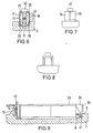
- the magazines 15, 16 have chambers 25 for receiving contact elements 26 (FIG. 6).
- they In extension of the side walls 27, 28, they have rail webs 29 which fit in a form-fitting manner into the angular recesses 21 of the angular rails 20, the free end edges 20a of the angular rails 20 resting on the upper edges 25a of the walls of the chambers 25.
- This configuration of the storage of the magazines despite the unstable fork-shaped design of the connector housing 13, results in a stable, self-supporting connector 1 made of uncomplicated spatial shapes that require little material and are easy to manufacture.
- the one magazine 15 has a half projection 30 which extends parallel to the longitudinal axis and the other magazine 16 has a projection 31 which forms the opposite half and which form-fit when the magazines are placed against one another Complete magazine cuboid shape.
- the projections 30 and 31 can - as shown - be equipped with chambers 25.
- tabs 32 At the front end of the side walls 17, 18 of the plug housing 13 there are aligned tabs 32 with latching holes 33 which form part of the latching device for the magazines 15, 16.
- the other part consists of tabs 34, which are connected in alignment at the front to the side walls 27, 28 of the magazine 16 and have locking lugs 35 on the outside, which can snap into the locking holes 33.
- tabs 34 At the end of the tabs 34 are arranged transversely extending handle webs 36 which form a slot 37 between them.
- the flaps 32 and 34 do not take up the entire width of the walls 17, 18 and 27, 28, respectively.
- a hinge tongue 40 which extends to the front and has a counter-hinge web 41 which can engage in a form-fitting manner under the hinge web 9 of the socket housing 3 (FIG. 9) when the plug housing 1 from the position shown in dashed lines in FIG the position drawn with excellent lines is pivoted into the pin tray 4 of the socket housing 3.
- a free-standing spring tongue 42 projecting upward from the bottom region is provided with a locking nose web 43, which engages in the undercut 12 when the connector housing 13 is inserted into the pin trough 4 and according to Fig. 5 is pivoted.
- a rearwardly extending handle plate 44 is formed on the rear end of the plug housing 13, which has a hole 45 which is penetrated by the upper part of the spring tongue 42.
- the plug housing 13 can be released by hand in a simple manner.
- the wall 46 has two vertical diaper rails 47 which extend in the direction of the housing 13, a stop web 48 projecting in the direction of the housing 13 being arranged on the lower edge of the wall 46 and a detent spring tongue 49 with detent spring nose 50 being free in the region of the upper edge.
- the wall 46 On the outside, the wall 46 carries the hinge tongue 40.
- vertical rail webs 51 are arranged at the end of the side walls 17, 18 and extend transversely to the longitudinal extent of the housing and fit positively into the rail recesses 47a of the diaper rails 47 .
- the closure wall 46 can be pushed onto the plug housing 13 in the direction of the arrow 52 until the stop web 48 abuts against the lower edge of the plug housing 13.
- the detent spring nose 50 jumps over the upper edge of the connector housing so that the opening 24 of the connector housing 13 is locked.
- spring tongues 53 are saved in the side walls 17, 18 opposite each other, which extend in the direction of the insertion opening 24 and on the outside one over the outer surface of the Have walls 17, 18 projecting handle 54.
- Spring tongues 55 with outside latching lugs 56 which are arranged opposite the projections 30, 31 on the side walls 27 and 28 and practically form an extension of the side walls, which is approximately as long as the projections 30, serve as counter-latching means on the magazines 15, 16.
- rectangular recesses 57 are made in the side walls 27, 28, which are deeper than the thickness the spring tongues is 55.
- the locking lugs 56 jump behind the front edge 58 of the recess 59.
- the locking lug 56 is pressed inwards until the locking edge 58 the latch 56 releases; because the recess 57 enables the detent spring tongues 55 to be pivoted in this way.
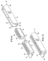
- the embodiment of the connector 1 according to FIGS. 13 and 14 shows that the insertion opening 24 can also be provided at the rear end of the connector housing.
- the latches of the magazines in the housing 13 correspond to the latching device according to FIGS. 11 and 12.
- the magazine 15 carries the handle plate 44 and the latch spring tongue 42 at the rear end.
- the embodiments of the connector housing 13 according to FIGS. 11 to 14 do not have a lower cutout 23, but instead a bottom wall 61 with holes 62 for the contact pins 6 to pass through.
- the connector housing 13 is torsionally stiff in these embodiments.
Landscapes
- Connector Housings Or Holding Contact Members (AREA)
Applications Claiming Priority (2)
| Application Number | Priority Date | Filing Date | Title |
|---|---|---|---|
| DE19873738593 DE3738593A1 (de) | 1987-11-13 | 1987-11-13 | Vielpolige elektrische steckvorrichtung |
| DE3738593 | 1987-11-13 |
Publications (2)
| Publication Number | Publication Date |
|---|---|
| EP0316678A2 true EP0316678A2 (fr) | 1989-05-24 |
| EP0316678A3 EP0316678A3 (fr) | 1990-03-07 |
Family
ID=6340440
Family Applications (1)
| Application Number | Title | Priority Date | Filing Date |
|---|---|---|---|
| EP88118366A Ceased EP0316678A3 (fr) | 1987-11-13 | 1988-11-04 | Dispositif de connexion électrique à pôles multiples |
Country Status (6)
| Country | Link |
|---|---|
| US (1) | US4923408A (fr) |
| EP (1) | EP0316678A3 (fr) |
| KR (1) | KR890009021A (fr) |
| DE (1) | DE3738593A1 (fr) |
| ES (1) | ES2010644A4 (fr) |
| GR (1) | GR890300163T1 (fr) |
Cited By (1)
| Publication number | Priority date | Publication date | Assignee | Title |
|---|---|---|---|---|
| EP0510229A1 (fr) * | 1991-04-25 | 1992-10-28 | Molex Incorporated | Connecteur électrique à verrouillage positif |
Families Citing this family (15)
| Publication number | Priority date | Publication date | Assignee | Title |
|---|---|---|---|---|
| US5148353A (en) * | 1990-06-29 | 1992-09-15 | Digital Equipment Corporation | Mounting system for installation of communication boxes having a convex bottom post and a rigid top post |
| JP2671729B2 (ja) * | 1992-09-29 | 1997-10-29 | 住友電装株式会社 | コネクタ装置 |
| US5443403A (en) * | 1993-03-10 | 1995-08-22 | The Whitaker Corporation | Composite electrical connector assembly with snap-in housing |
| JPH07142120A (ja) * | 1993-11-19 | 1995-06-02 | Sumitomo Wiring Syst Ltd | 低嵌合型コネクタ |
| US5785558A (en) * | 1995-11-21 | 1998-07-28 | The Whitaker Corporation | Electrical connector assembly |
| DE19543423A1 (de) * | 1995-11-21 | 1997-05-22 | Whitaker Corp | Steckverbinder |
| EP0776068B1 (fr) * | 1995-11-21 | 2001-06-06 | The Whitaker Corporation | Assemblage de connecteur électrique |
| US5944560A (en) * | 1997-09-05 | 1999-08-31 | Molex Incorporated | Frame structure for mounting an electrical connector |
| DE19739503C2 (de) * | 1997-09-09 | 2000-05-18 | Siemens Ag | Elektrischer Steckverbinder |
| JP3681566B2 (ja) * | 1999-02-08 | 2005-08-10 | 矢崎総業株式会社 | レバー嵌合式コネクタ |
| DE20011382U1 (de) * | 2000-06-29 | 2001-11-08 | Siemens Building Technologies AG, Zürich | Verbindungsmodul |
| US6547605B2 (en) * | 2001-07-20 | 2003-04-15 | Delphi Technologies, Inc. | Flex circuit electrical connector |
| US9287666B2 (en) * | 2011-05-03 | 2016-03-15 | Cardioinsight Technologies, Inc. | Electrical connector plug with key to avoid contact damage |
| DE102012221115A1 (de) | 2012-11-19 | 2014-05-22 | Tyco Electronics Amp Gmbh | Steckerelement mit Kontaktmodulverrastung |
| CN108808370B (zh) * | 2018-07-17 | 2024-11-15 | 中国工程物理研究院机械制造工艺研究所 | 一种用于狭窄空间的电缆头插接导向装置 |
Family Cites Families (6)
| Publication number | Priority date | Publication date | Assignee | Title |
|---|---|---|---|---|
| US3399374A (en) * | 1966-07-14 | 1968-08-27 | Amp Inc | Disengageable electrical connections |
| US4082400A (en) * | 1973-11-02 | 1978-04-04 | Robert Bosch Gmbh | Multi-pole plug-and-socket connecting arrangement |
| US4130329A (en) * | 1977-10-06 | 1978-12-19 | Amp Incorporated | Electrical connector assembly retention system |
| CA1096951A (fr) * | 1978-02-03 | 1981-03-03 | Amp Incorporated | Traduction non-disponible |
| DE8518867U1 (de) * | 1985-06-28 | 1985-08-08 | Siemens AG, 1000 Berlin und 8000 München | Leitungsstecker-Gehäuse |
| DE3603750C3 (de) * | 1986-02-06 | 1996-10-17 | Siemens Ag | Automatisierungsgerät |
-
1987
- 1987-11-13 DE DE19873738593 patent/DE3738593A1/de not_active Withdrawn
-
1988
- 1988-11-04 EP EP88118366A patent/EP0316678A3/fr not_active Ceased
- 1988-11-04 ES ES88118366T patent/ES2010644A4/es active Pending
- 1988-11-08 US US07/268,813 patent/US4923408A/en not_active Expired - Fee Related
- 1988-11-12 KR KR1019880014899A patent/KR890009021A/ko not_active Withdrawn
-
1990
- 1990-05-11 GR GR89300163T patent/GR890300163T1/el unknown
Cited By (1)
| Publication number | Priority date | Publication date | Assignee | Title |
|---|---|---|---|---|
| EP0510229A1 (fr) * | 1991-04-25 | 1992-10-28 | Molex Incorporated | Connecteur électrique à verrouillage positif |
Also Published As
| Publication number | Publication date |
|---|---|
| ES2010644A4 (es) | 1989-12-01 |
| EP0316678A3 (fr) | 1990-03-07 |
| US4923408A (en) | 1990-05-08 |
| KR890009021A (ko) | 1989-07-13 |
| GR890300163T1 (en) | 1990-05-11 |
| DE3738593A1 (de) | 1989-05-24 |
Similar Documents
| Publication | Publication Date | Title |
|---|---|---|
| DE69311012T2 (de) | Elektrischer Verbinder | |
| EP0273999B1 (fr) | Arrangement d'un connecteur à levier à crémaillère | |
| DE3600523C2 (de) | Verriegelungsvorrichtung für elektrische Steckverbindungen | |
| DE69409771T2 (de) | Steckverbindersystem mit geringer Einsteckkraft | |
| EP0316678A2 (fr) | Dispositif de connexion électrique à pôles multiples | |
| DE19916865A1 (de) | Elektrisches Steckerbuchsenanschlußstück | |
| DE3725668C2 (fr) | ||
| DE20117652U1 (de) | Verbindungseinheit für elektrische Leiter | |
| DE2925739C2 (fr) | ||
| DE69300092T2 (de) | Elektrischer Gehäusewandverbinder. | |
| DE69708734T2 (de) | Abgeschirmter Verbinder, insbesondere mit Stecker und Ablagefläche zum Verbinden auf einer ebenen Unterlage | |
| DE8715118U1 (de) | Vielpolige elektrische Steckvorrichtung | |
| EP0437782A2 (fr) | Fiche électrique | |
| DE2728429A1 (de) | Elektrische steckvorrichtung mit mitteln zur verhinderung der beruehrung stromfuehrender teile | |
| DE2817005C2 (de) | Vorrichtung zur Magazinierung und flächenparallelen Halterung mehrerer Diarahmen in einem Magazin und zur Aufnahme in dem Magazin geeigneter Diarahmen | |
| EP0648382B1 (fr) | Connecteur de filtrage a fiches avec boitier de blindage | |
| DE3911696C2 (fr) | ||
| DE2852796A1 (de) | Anschlusstecker fuer mehrpolige elektrische verbindungen | |
| EP0093236B1 (fr) | Fiche pour appareil | |
| DE3906421A1 (de) | Verriegelbarer steckverbinder | |
| DE3025634A1 (de) | Zwitterstecker | |
| DE19852385B4 (de) | Werkzeug zum Entriegeln von elektrischen Flachsteckern | |
| DE19744520C1 (de) | Steckbuchse eines Steckverbinders für Datenübertragungssysteme | |
| DE4204387A1 (de) | Blechschubkasten | |
| DE10064374B4 (de) | Steckverbinder zur Verbindung von Schaltkreisplatten |
Legal Events
| Date | Code | Title | Description |
|---|---|---|---|
| PUAI | Public reference made under article 153(3) epc to a published international application that has entered the european phase |
Free format text: ORIGINAL CODE: 0009012 |
|
| AK | Designated contracting states |
Kind code of ref document: A2 Designated state(s): AT BE CH DE ES FR GB GR IT LI LU NL SE |
|
| ITCL | It: translation for ep claims filed |
Representative=s name: ING. A. GIAMBROCONO & C. S.R.L. |
|
| EL | Fr: translation of claims filed | ||
| TCNL | Nl: translation of patent claims filed | ||
| GBC | Gb: translation of claims filed (gb section 78(7)/1977) | ||
| PUAL | Search report despatched |
Free format text: ORIGINAL CODE: 0009013 |
|
| AK | Designated contracting states |
Kind code of ref document: A3 Designated state(s): AT BE CH DE ES FR GB GR IT LI LU NL SE |
|
| 17P | Request for examination filed |
Effective date: 19900226 |
|
| 17Q | First examination report despatched |
Effective date: 19911114 |
|
| STAA | Information on the status of an ep patent application or granted ep patent |
Free format text: STATUS: THE APPLICATION HAS BEEN REFUSED |
|
| 18R | Application refused |
Effective date: 19920510 |