EP0316688A2 - Dispositif de prise d'échantillons de gaz - Google Patents
Dispositif de prise d'échantillons de gaz Download PDFInfo
- Publication number
- EP0316688A2 EP0316688A2 EP88118444A EP88118444A EP0316688A2 EP 0316688 A2 EP0316688 A2 EP 0316688A2 EP 88118444 A EP88118444 A EP 88118444A EP 88118444 A EP88118444 A EP 88118444A EP 0316688 A2 EP0316688 A2 EP 0316688A2
- Authority
- EP
- European Patent Office
- Prior art keywords
- gas
- passage
- flow rate
- gas sampling
- venturi
- Prior art date
- Legal status (The legal status is an assumption and is not a legal conclusion. Google has not performed a legal analysis and makes no representation as to the accuracy of the status listed.)
- Granted
Links
Images

Classifications
-
- G—PHYSICS
- G01—MEASURING; TESTING
- G01N—INVESTIGATING OR ANALYSING MATERIALS BY DETERMINING THEIR CHEMICAL OR PHYSICAL PROPERTIES
- G01N1/00—Sampling; Preparing specimens for investigation
- G01N1/02—Devices for withdrawing samples
- G01N1/22—Devices for withdrawing samples in the gaseous state
- G01N1/2247—Sampling from a flowing stream of gas
- G01N1/2258—Sampling from a flowing stream of gas in a stack or chimney
-
- G—PHYSICS
- G01—MEASURING; TESTING
- G01N—INVESTIGATING OR ANALYSING MATERIALS BY DETERMINING THEIR CHEMICAL OR PHYSICAL PROPERTIES
- G01N1/00—Sampling; Preparing specimens for investigation
- G01N1/02—Devices for withdrawing samples
- G01N1/22—Devices for withdrawing samples in the gaseous state
- G01N1/2247—Sampling from a flowing stream of gas
- G01N1/2252—Sampling from a flowing stream of gas in a vehicle exhaust
-
- G—PHYSICS
- G01—MEASURING; TESTING
- G01N—INVESTIGATING OR ANALYSING MATERIALS BY DETERMINING THEIR CHEMICAL OR PHYSICAL PROPERTIES
- G01N1/00—Sampling; Preparing specimens for investigation
- G01N1/02—Devices for withdrawing samples
- G01N1/22—Devices for withdrawing samples in the gaseous state
- G01N1/24—Suction devices
-
- G—PHYSICS
- G01—MEASURING; TESTING
- G01N—INVESTIGATING OR ANALYSING MATERIALS BY DETERMINING THEIR CHEMICAL OR PHYSICAL PROPERTIES
- G01N1/00—Sampling; Preparing specimens for investigation
- G01N1/28—Preparing specimens for investigation including physical details of (bio-)chemical methods covered elsewhere, e.g. G01N33/50, C12Q
- G01N1/38—Diluting, dispersing or mixing samples
-
- G—PHYSICS
- G01—MEASURING; TESTING
- G01N—INVESTIGATING OR ANALYSING MATERIALS BY DETERMINING THEIR CHEMICAL OR PHYSICAL PROPERTIES
- G01N1/00—Sampling; Preparing specimens for investigation
- G01N1/02—Devices for withdrawing samples
- G01N1/22—Devices for withdrawing samples in the gaseous state
- G01N1/2247—Sampling from a flowing stream of gas
- G01N2001/2264—Sampling from a flowing stream of gas with dilution
-
- G—PHYSICS
- G01—MEASURING; TESTING
- G01N—INVESTIGATING OR ANALYSING MATERIALS BY DETERMINING THEIR CHEMICAL OR PHYSICAL PROPERTIES
- G01N1/00—Sampling; Preparing specimens for investigation
- G01N1/02—Devices for withdrawing samples
- G01N1/22—Devices for withdrawing samples in the gaseous state
- G01N1/24—Suction devices
- G01N2001/242—Injectors or ejectors
- G01N2001/244—Injectors or ejectors using critical flow orifices
Definitions
- the present invention relates to a gas sampling device use for example to measure the total quantity of exhaust substances (i.e. emissions of for example CO, CO2, hydrocarbons HC, NO x , particulate solids, SO x and the like) contained in the exhaust gas of an automotive vehicle.
- exhaust substances i.e. emissions of for example CO, CO2, hydrocarbons HC, NO x , particulate solids, SO x and the like
- a conventional method of measuring the total or absolute quantity of exhaust gas emissions is the so-called CVS method (Constant Volume Sampling method).
- CVS method Constant Volume Sampling method
- the sampling device needed for carrying out this method has shown disadvantages in that it is expensive and has a large-size and complex construction.
- the bulk construction of the sampling device turned out to be a significant drawback in cases where the vehicle to be tested is a large-sized vehicle such as a truck or a bus.
- FIG. 60-127,420 Another example of a conventional gas sampling device is disclosed in Japanese Patent Laid-Open No. Sho 60-127,420.
- This gas sampling device is provided with a proportional divider which is formed by a plurality of pipings having an equal passage resistance and uniformly divides the flow of exhaust gas within an intermediate portion of an exhaust passage through which the exhaust gas from the engine of the vehicle is discharged.
- a sample probe is formed by anyone of the pipings forming the proportional divider, and an exhaust gas sample proportional to the flow rate of the exhaust gas within the exhaust gas passage is taken out by this sample probe.
- a gas sampling device of the so-called ejector mode which is adapted to suck a part of the exhaust gas by the use of an ejector, as is shown in "Motor Vehicle Technique", Vol. 40, No. 11 (1986), pp 1455 to 1466.
- a sampling device of this type is used in cases where the quantity of the exhaust gas is dynamically changed, it is necessary to control the quantity of a dilution gas (for example air) in such a manner that it changes in correspondence to the change in quantity of the exhaust gas.
- a problem was encountered in that the control of the quantity of the dilution gas can only follow the changes of the quantity of the exhaust gas with a certain time-lag. It is therefore difficult to apply this sampling method to transient running conditions of the engine.
- the present invention has been devised in view of the above described drawbacks of the prior art systems, and it is an object of the invention to provide a gas sampling device which is small-sized, inexpensive and applicable under transient running conditions of the engine.
- a gas sampling device embodying the invention the sample gas flowing through a gas passage is divided at an appointed partition ratio by means of two venturi tubes which have different sizes and are connected in parallel, and the sample gas which has flown through the smaller venturi tube is diluted in a dilution gas passage.
- the diluted sample gas is again divided at an appointed partition ratio by means of a constant-flow rate device and a gas sampling passage connected to the constant flow rate device in parallel with each other.
- the gas to be measured can always be divided at the accurate ratio. Further, since the sample gas is divided by means of venturi tubes, the tendency of mists and the like to adhere to the walls of the flow dividing system is reduced. Due to the simple structure of the gas sampling device, the gas sampling can be achieved at low costs and maintenance of the device is facilitated.
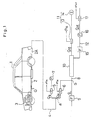
- reference numberal 1 designates a car and reference numberal 2 designates an exhaust pipe for discharging an exhaust gas (hereinafter referred to as a sample gas) G exhausted from an engine 3 of the car 1.
- a sample gas exhaust gas
- Reference numeral 4 designates a gas passage connected to an exhaust port 2A of the exhaust pipe 2.
- Two venturi tubes 5,6 having different sizes are connected in parallel to a downstream side of the gas passage 4, and the sample gas G which has flown through the gas passage 4 is divided at an appointed partition ratio, for example 99:1, at a branching point a .
- the gas flow rates Q5,Q6 through the venturi tubes 5,6 are usually determined by parameters such as the venturi differential pressure, the inlet pressure, the gas temperature, the gas composition and the venturi tube sizes.
- the structure including the venturi tubes 5,6 is so designed that, with exception of the venturi tube sizes, all parameters are the same for both venturi tubes and the characteristics of the gas flow rate Q versus the total venturi differential pressure ⁇ P for the two venturi tubes 5,6 have a similar shape, as is shown for example in figs. 2 (A) and 2 (B).
- the "total venturi differential pressure" is defined as the difference between the inlet pressure and the outlet pressure of the respective venturi tube.
- venturi tube sizes for example the throat sectional areas
- the venturi tube sizes are selected so that, when the diagrams shown in figs. 2(A), (B) are superposed to each other, the two curves are congruent with each other and the gas flow rate ratio Q5:Q6 amounts to for example 99:1.
- the gas flow rate Q6 flowing through the smaller venturi tube 6 is constantly 1/100 times the flow rate of the sample gas G through the gas passage 4.
- a constant-flow rate suction pump 7 is disposed on the downstream side of the venturi tube 5.
- Reference numeral 8 designates a dilution gas passage disposed independently at the above described gas passage 4 and provided with a filter 9 and a dilution tunnel 10 disposed in this order in the direction of gas flow.
- a dilution gas flowing through the dilution gas passage is formed by air g which has passed through the filter 9.
- the downstream side of the venturi tube 6 is connected to the dilution gas passage 8 at a point b between the filter 9 and the dilution tunnel 10 so that the sample gas G which has flown through the venturi tube 6 may be uniformly diluted within the dilution tunnel 10.
- Reference numerals 11,12 designate a constant-flow rate device and a gas sampling passage, respectively, which are connected in parallel to the downstream end of the dilution tunnel 10 and are adapted to divide the sample gas G which has been diluted within the dilution tunnel 10 at an appointed partition ratio.
- the constant-flow rate device 11 comprises for example a critical flow venturi 13 and a blower 14 connected to the downstream end thereof.
- the gas sampling passage 12 is provided with a particulate solid collecting filter 15, a constant-flow rate suction pump 16 and a venturi tube 17 disposed in this order in the direction of gas flow.
- the venturi tube sizes (for example the throat sectional areas) of the venturi tubes 13,17 are selected so that the ratio Q13 : Q17 of the gas flow rate Q13 through the critical flow venturi 13 to the gas flow rate Q17 through the venturi tube 17 amounts for example to 99:1. Accordingly, the flow rate Q17 of the gas flowing through the venturi tube 17 (the sampling gas passage 12) is 1/100 times that of the sample gas G flowing through the dilution gas passage 8.
- Fig. 3 is a block diagram showing an example of a control system for the gas sampling device having the above described construction.
- reference numerals 21,22,23,24 designate operational circuits
- reference numeral 25 designates an operating control apparatus, such as a CPU, for processing the outputs from the operational circuits 21 to 24 and outputting a control signal.
- Reference numeral 26 designates a controller for controlling the rotational frequency of the pump 16 on the basis of the control signal received from the CPU 25.
- the operational circuits 21 to 24 receive signals representing the throat differential pressure ⁇ P s5 in the venturi tube 5, the throat differential pressure ⁇ P s6 in the venturi tube 6, the inlet pressure P13 in the venturi tube 13 and the throat differential pressure ⁇ P s17 in the venturi tube 17, respectively. These signals are used for determining the gas flow rates Q5, Q6, Q13, Q17 through the respective venturi tubes 5,6,13,17.
- emissions other than particulate solids can be continuously measured gravimetrically by sampling a part of the sample gas G sucked by the constant flow-rate device 11 and introducing it into gas analyzers for CO, CO2, HC, NO x , SO x and the like. In this case, if the outputs from the analyzers are processed in view of the ratio of the flow rate Q5 to the flow rate Q6, a still more accurate measurement can be achieved.
Landscapes
- Health & Medical Sciences (AREA)
- Life Sciences & Earth Sciences (AREA)
- Engineering & Computer Science (AREA)
- Biomedical Technology (AREA)
- Molecular Biology (AREA)
- Physics & Mathematics (AREA)
- Chemical & Material Sciences (AREA)
- Analytical Chemistry (AREA)
- Biochemistry (AREA)
- General Health & Medical Sciences (AREA)
- General Physics & Mathematics (AREA)
- Immunology (AREA)
- Pathology (AREA)
- Sampling And Sample Adjustment (AREA)
Applications Claiming Priority (2)
| Application Number | Priority Date | Filing Date | Title |
|---|---|---|---|
| JP292582/87 | 1987-11-18 | ||
| JP62292582A JPH07104233B2 (ja) | 1987-11-18 | 1987-11-18 | ガスサンプリング装置 |
Publications (3)
| Publication Number | Publication Date |
|---|---|
| EP0316688A2 true EP0316688A2 (fr) | 1989-05-24 |
| EP0316688A3 EP0316688A3 (en) | 1990-03-28 |
| EP0316688B1 EP0316688B1 (fr) | 1992-09-30 |
Family
ID=17783640
Family Applications (1)
| Application Number | Title | Priority Date | Filing Date |
|---|---|---|---|
| EP19880118444 Expired EP0316688B1 (fr) | 1987-11-18 | 1988-11-04 | Dispositif de prise d'échantillons de gaz |
Country Status (3)
| Country | Link |
|---|---|
| EP (1) | EP0316688B1 (fr) |
| JP (1) | JPH07104233B2 (fr) |
| DE (1) | DE3875071T2 (fr) |
Cited By (10)
| Publication number | Priority date | Publication date | Assignee | Title |
|---|---|---|---|---|
| WO1992004611A1 (fr) * | 1990-09-04 | 1992-03-19 | Caterpillar Inc. | Dispositif d'echantillonnage des gaz d'echappement et tunnel de dilution connexe |
| EP0471174A3 (en) * | 1990-08-14 | 1993-06-02 | Steyr Nutzfahrzeuge Ag | Installation for analyzing pollutants, in particular particulate emission of exhaust gas of diesel engines, with a dilution device for a partial current |
| EP0561557A1 (fr) * | 1992-03-18 | 1993-09-22 | Horiba Instruments Incorporated | Procédés et appareil d'échantillonnage proportionnel à venturi subsonique et isocinétique |
| EP0967473A1 (fr) * | 1998-06-25 | 1999-12-29 | Institut Francais Du Petrole | Procédé et unite de prelevement d'aldehydes et cetones contenus dans des gaz d'échappement |
| GB2352196A (en) * | 1999-06-09 | 2001-01-24 | Air Dispersions Ltd | Gas sampling device with flow divider |
| EP0928962A4 (fr) * | 1996-09-27 | 2004-06-16 | Hino Motors Ltd | Instrument de mesure des gaz d'echappement |
| CN101393222B (zh) * | 2007-09-20 | 2012-07-18 | 财团法人工业技术研究院 | 有机气体监测装置及方法 |
| WO2015053794A1 (fr) * | 2013-10-11 | 2015-04-16 | Draeger Safety, Inc. | Dérivation d'échantillonnage à distance pour analyseur de gaz |
| CN106289805A (zh) * | 2016-08-23 | 2017-01-04 | 苏州华业检测技术服务有限公司 | 一种汽车尾气流量测量控制系统及检测方法 |
| US10968781B2 (en) | 2015-03-04 | 2021-04-06 | General Electric Company | System and method for cooling discharge flow |
Families Citing this family (4)
| Publication number | Priority date | Publication date | Assignee | Title |
|---|---|---|---|---|
| JPH04152240A (ja) * | 1990-10-16 | 1992-05-26 | Hino Motors Ltd | 排気ガス測定装置 |
| JP3604060B2 (ja) * | 1998-07-17 | 2004-12-22 | 株式会社堀場製作所 | 希釈用ガス流量制御装置 |
| JP3604059B2 (ja) * | 1998-07-17 | 2004-12-22 | 株式会社堀場製作所 | 部分希釈方式のガス希釈システム |
| CN105203356A (zh) * | 2015-10-15 | 2015-12-30 | 长沙华时捷环保科技发展有限公司 | 一种便携式烟气采样装置 |
Family Cites Families (6)
| Publication number | Priority date | Publication date | Assignee | Title |
|---|---|---|---|---|
| US3699814A (en) * | 1972-03-09 | 1972-10-24 | Philco Ford Corp | Gas sampler |
| SE370562B (fr) * | 1973-02-15 | 1974-10-21 | Collin Consult Ab Lars | |
| JPS5130794A (fr) * | 1974-09-09 | 1976-03-16 | Soichi Takemoto | |
| JPS59180653U (ja) * | 1983-05-20 | 1984-12-03 | 財団法人 日本自動車研究所 | 内燃機関の排出ガス採取装置 |
| JPS60127420U (ja) * | 1984-02-06 | 1985-08-27 | 三菱自動車工業株式会社 | 排気ガスサンプル取り出し装置 |
| US4586367A (en) * | 1984-03-19 | 1986-05-06 | Horiba Instruments Incorporated | Proportional exhaust sampler and control means |
-
1987
- 1987-11-18 JP JP62292582A patent/JPH07104233B2/ja not_active Expired - Fee Related
-
1988
- 1988-11-04 EP EP19880118444 patent/EP0316688B1/fr not_active Expired
- 1988-11-04 DE DE19883875071 patent/DE3875071T2/de not_active Expired - Fee Related
Cited By (16)
| Publication number | Priority date | Publication date | Assignee | Title |
|---|---|---|---|---|
| EP0471174A3 (en) * | 1990-08-14 | 1993-06-02 | Steyr Nutzfahrzeuge Ag | Installation for analyzing pollutants, in particular particulate emission of exhaust gas of diesel engines, with a dilution device for a partial current |
| WO1992004611A1 (fr) * | 1990-09-04 | 1992-03-19 | Caterpillar Inc. | Dispositif d'echantillonnage des gaz d'echappement et tunnel de dilution connexe |
| EP0561557A1 (fr) * | 1992-03-18 | 1993-09-22 | Horiba Instruments Incorporated | Procédés et appareil d'échantillonnage proportionnel à venturi subsonique et isocinétique |
| EP0928962A4 (fr) * | 1996-09-27 | 2004-06-16 | Hino Motors Ltd | Instrument de mesure des gaz d'echappement |
| EP0967473A1 (fr) * | 1998-06-25 | 1999-12-29 | Institut Francais Du Petrole | Procédé et unite de prelevement d'aldehydes et cetones contenus dans des gaz d'échappement |
| FR2780506A1 (fr) * | 1998-06-25 | 1999-12-31 | Inst Francais Du Petrole | Procede et unite de prelevement d'aldehydes et cetones contenus dans des gaz d'echappement |
| US6339965B1 (en) | 1998-06-25 | 2002-01-22 | Institut Francais Du Petrole | Process and unit for sampling aldehydes and ketones contained in exhaust gases |
| US6513397B2 (en) | 1998-06-25 | 2003-02-04 | Institut Francais Du Petrole | Process and unit for sampling aldehydes and ketones contained in exhaust gases |
| GB2352196B (en) * | 1999-06-09 | 2003-03-26 | Air Dispersions Ltd | Sampling devices |
| US6553848B1 (en) | 1999-06-09 | 2003-04-29 | Air Dispersions Ltd. | Sampling devices |
| GB2352196A (en) * | 1999-06-09 | 2001-01-24 | Air Dispersions Ltd | Gas sampling device with flow divider |
| CN101393222B (zh) * | 2007-09-20 | 2012-07-18 | 财团法人工业技术研究院 | 有机气体监测装置及方法 |
| WO2015053794A1 (fr) * | 2013-10-11 | 2015-04-16 | Draeger Safety, Inc. | Dérivation d'échantillonnage à distance pour analyseur de gaz |
| US9952125B2 (en) | 2013-10-11 | 2018-04-24 | Draeger Medical Systems, Inc. | Remote sampling bypass for a gas analyser |
| US10968781B2 (en) | 2015-03-04 | 2021-04-06 | General Electric Company | System and method for cooling discharge flow |
| CN106289805A (zh) * | 2016-08-23 | 2017-01-04 | 苏州华业检测技术服务有限公司 | 一种汽车尾气流量测量控制系统及检测方法 |
Also Published As
| Publication number | Publication date |
|---|---|
| DE3875071T2 (de) | 1993-02-18 |
| EP0316688A3 (en) | 1990-03-28 |
| DE3875071D1 (de) | 1992-11-05 |
| JPH07104233B2 (ja) | 1995-11-13 |
| JPH01132929A (ja) | 1989-05-25 |
| EP0316688B1 (fr) | 1992-09-30 |
Similar Documents
| Publication | Publication Date | Title |
|---|---|---|
| EP0316688B1 (fr) | Dispositif de prise d'échantillons de gaz | |
| US4361028A (en) | System for measuring particulate discharge from vehicular internal combustion engine | |
| EP1073885B1 (fr) | Procede de mesure d'une fraction de masse gazeuse | |
| US10428715B2 (en) | Exhaust gas analyzing system and pumping device | |
| EP0561557B1 (fr) | Procédés et appareil d'échantillonnage proportionnel à venturi subsonique et isocinétique | |
| EP0428850B1 (fr) | Système de dilution utilisant un diviseur de débit à conduites multiples | |
| EP0971211A2 (fr) | Méthode d'échantillonage de gaz d'échappement utilisant un débitmètre à venturi variable | |
| US6370936B1 (en) | Sampling apparatus for exhaust gas | |
| CN106092839B (zh) | 排气测量装置以及排气测量方法 | |
| US4555931A (en) | Apparatus for measuring or controlling the separation ratio of gas | |
| JP2000028499A (ja) | 排気ガス中の混合物質捕集装置 | |
| DE60209466T2 (de) | Aktive Druckschwingungsdämpfer zur Probenentnahme von Teilchen aus Dieselmotoren | |
| JPS60225029A (ja) | 排気ガス測定方法 | |
| US20080087107A1 (en) | Particulate sampler and dilution gas flow device arrangement for an exhaust sampling system | |
| JPH05312695A (ja) | 希釈トンネル法によるパーティキュレート捕集装置 | |
| GB2336681A (en) | Measuring a gas mass fraction | |
| KR100210664B1 (ko) | 자동차의 배기가스 채집장치 | |
| JPH04310822A (ja) | 排気ガス定流量採取方法及び可変ベンチュリ式定流量測定制御装置 | |
| JP2580749B2 (ja) | 排気ガス導入装置の排気ガス分析方法 | |
| JP4300350B2 (ja) | 排ガス測定装置及び排ガス測定方法 | |
| JP2526299Y2 (ja) | 排気ガスの分流装置 | |
| JP2739491B2 (ja) | 排気ガス測定装置 | |
| JP3030355B2 (ja) | 多管式分流希釈トンネル及びその制御方法 | |
| JP3992121B2 (ja) | 排気ガス希釈サンプリング装置 | |
| JPS6093940A (ja) | サンプリング装置 |
Legal Events
| Date | Code | Title | Description |
|---|---|---|---|
| PUAI | Public reference made under article 153(3) epc to a published international application that has entered the european phase |
Free format text: ORIGINAL CODE: 0009012 |
|
| AK | Designated contracting states |
Kind code of ref document: A2 Designated state(s): CH DE FR GB IT LI SE |
|
| PUAL | Search report despatched |
Free format text: ORIGINAL CODE: 0009013 |
|
| AK | Designated contracting states |
Kind code of ref document: A3 Designated state(s): CH DE FR GB IT LI SE |
|
| 17P | Request for examination filed |
Effective date: 19900525 |
|
| 17Q | First examination report despatched |
Effective date: 19910611 |
|
| GRAA | (expected) grant |
Free format text: ORIGINAL CODE: 0009210 |
|
| AK | Designated contracting states |
Kind code of ref document: B1 Designated state(s): CH DE FR GB IT LI SE |
|
| REF | Corresponds to: |
Ref document number: 3875071 Country of ref document: DE Date of ref document: 19921105 |
|
| ET | Fr: translation filed | ||
| ITF | It: translation for a ep patent filed | ||
| PLBE | No opposition filed within time limit |
Free format text: ORIGINAL CODE: 0009261 |
|
| STAA | Information on the status of an ep patent application or granted ep patent |
Free format text: STATUS: NO OPPOSITION FILED WITHIN TIME LIMIT |
|
| 26N | No opposition filed | ||
| PGFP | Annual fee paid to national office [announced via postgrant information from national office to epo] |
Ref country code: GB Payment date: 19931102 Year of fee payment: 6 |
|
| PGFP | Annual fee paid to national office [announced via postgrant information from national office to epo] |
Ref country code: SE Payment date: 19931117 Year of fee payment: 6 |
|
| PGFP | Annual fee paid to national office [announced via postgrant information from national office to epo] |
Ref country code: FR Payment date: 19931119 Year of fee payment: 6 |
|
| PGFP | Annual fee paid to national office [announced via postgrant information from national office to epo] |
Ref country code: CH Payment date: 19931126 Year of fee payment: 6 |
|
| PG25 | Lapsed in a contracting state [announced via postgrant information from national office to epo] |
Ref country code: GB Effective date: 19941104 |
|
| PG25 | Lapsed in a contracting state [announced via postgrant information from national office to epo] |
Ref country code: SE Effective date: 19941105 |
|
| PG25 | Lapsed in a contracting state [announced via postgrant information from national office to epo] |
Ref country code: LI Effective date: 19941130 Ref country code: CH Effective date: 19941130 |
|
| EAL | Se: european patent in force in sweden |
Ref document number: 88118444.4 |
|
| GBPC | Gb: european patent ceased through non-payment of renewal fee |
Effective date: 19941104 |
|
| PG25 | Lapsed in a contracting state [announced via postgrant information from national office to epo] |
Ref country code: FR Effective date: 19950731 |
|
| REG | Reference to a national code |
Ref country code: CH Ref legal event code: PL |
|
| EUG | Se: european patent has lapsed |
Ref document number: 88118444.4 |
|
| REG | Reference to a national code |
Ref country code: FR Ref legal event code: ST |
|
| PGFP | Annual fee paid to national office [announced via postgrant information from national office to epo] |
Ref country code: DE Payment date: 19971110 Year of fee payment: 10 |
|
| PG25 | Lapsed in a contracting state [announced via postgrant information from national office to epo] |
Ref country code: DE Free format text: LAPSE BECAUSE OF NON-PAYMENT OF DUE FEES Effective date: 19990901 |
|
| PG25 | Lapsed in a contracting state [announced via postgrant information from national office to epo] |
Ref country code: IT Free format text: LAPSE BECAUSE OF NON-PAYMENT OF DUE FEES Effective date: 20051104 |