EP0316716A2 - Moteur à courant continu sans balais pour ventilateurs de moteur, pompes et équipements similaires - Google Patents
Moteur à courant continu sans balais pour ventilateurs de moteur, pompes et équipements similaires Download PDFInfo
- Publication number
- EP0316716A2 EP0316716A2 EP88118574A EP88118574A EP0316716A2 EP 0316716 A2 EP0316716 A2 EP 0316716A2 EP 88118574 A EP88118574 A EP 88118574A EP 88118574 A EP88118574 A EP 88118574A EP 0316716 A2 EP0316716 A2 EP 0316716A2
- Authority
- EP
- European Patent Office
- Prior art keywords
- motor
- block
- windings
- phase
- speed
- Prior art date
- Legal status (The legal status is an assumption and is not a legal conclusion. Google has not performed a legal analysis and makes no representation as to the accuracy of the status listed.)
- Granted
Links
Images



Classifications
-
- H—ELECTRICITY
- H02—GENERATION; CONVERSION OR DISTRIBUTION OF ELECTRIC POWER
- H02P—CONTROL OR REGULATION OF ELECTRIC MOTORS, ELECTRIC GENERATORS OR DYNAMO-ELECTRIC CONVERTERS; CONTROLLING TRANSFORMERS, REACTORS OR CHOKE COILS
- H02P6/00—Arrangements for controlling synchronous motors or other dynamo-electric motors using electronic commutation dependent on the rotor position; Electronic commutators therefor
- H02P6/20—Arrangements for starting
- H02P6/22—Arrangements for starting in a selected direction of rotation
-
- H—ELECTRICITY
- H02—GENERATION; CONVERSION OR DISTRIBUTION OF ELECTRIC POWER
- H02P—CONTROL OR REGULATION OF ELECTRIC MOTORS, ELECTRIC GENERATORS OR DYNAMO-ELECTRIC CONVERTERS; CONTROLLING TRANSFORMERS, REACTORS OR CHOKE COILS
- H02P6/00—Arrangements for controlling synchronous motors or other dynamo-electric motors using electronic commutation dependent on the rotor position; Electronic commutators therefor
- H02P6/06—Arrangements for speed regulation of a single motor wherein the motor speed is measured and compared with a given physical value so as to adjust the motor speed
-
- H—ELECTRICITY
- H02—GENERATION; CONVERSION OR DISTRIBUTION OF ELECTRIC POWER
- H02P—CONTROL OR REGULATION OF ELECTRIC MOTORS, ELECTRIC GENERATORS OR DYNAMO-ELECTRIC CONVERTERS; CONTROLLING TRANSFORMERS, REACTORS OR CHOKE COILS
- H02P6/00—Arrangements for controlling synchronous motors or other dynamo-electric motors using electronic commutation dependent on the rotor position; Electronic commutators therefor
- H02P6/14—Electronic commutators
- H02P6/15—Controlling commutation time
- H02P6/153—Controlling commutation time wherein the commutation is advanced from position signals phase in function of the speed
-
- H—ELECTRICITY
- H02—GENERATION; CONVERSION OR DISTRIBUTION OF ELECTRIC POWER
- H02P—CONTROL OR REGULATION OF ELECTRIC MOTORS, ELECTRIC GENERATORS OR DYNAMO-ELECTRIC CONVERTERS; CONTROLLING TRANSFORMERS, REACTORS OR CHOKE COILS
- H02P6/00—Arrangements for controlling synchronous motors or other dynamo-electric motors using electronic commutation dependent on the rotor position; Electronic commutators therefor
- H02P6/14—Electronic commutators
- H02P6/16—Circuit arrangements for detecting position
- H02P6/18—Circuit arrangements for detecting position without separate position detecting elements
-
- H—ELECTRICITY
- H02—GENERATION; CONVERSION OR DISTRIBUTION OF ELECTRIC POWER
- H02P—CONTROL OR REGULATION OF ELECTRIC MOTORS, ELECTRIC GENERATORS OR DYNAMO-ELECTRIC CONVERTERS; CONTROLLING TRANSFORMERS, REACTORS OR CHOKE COILS
- H02P2209/00—Indexing scheme relating to controlling arrangements characterised by the waveform of the supplied voltage or current
- H02P2209/07—Trapezoidal waveform
Definitions
- Object of this invention is an electronically driven, brushless, direct current motor system, for motor fans, pumps and similar equipments.
- This invention proposes a motor of this type offering competitive quality and cost when compared to the ones utilized at the moment with equal production means; this originates from a design offering the following advantages to equal performance:
- the motor according to the invention that is a direct current brushless, electronically driven motor, biphase type with four unipolar windings; the motor is characterized in that the geometry of the teeth and of the magnet generated field is such that in each winding a trapezoidal e.m.f.
- the two phases are embodied to obtain conduction on 180° per winding, thus as two single-phase in parallel; furthermore, the two single-phases may be embodied in a different way to permit the electronic selection of the use of three distinct motors into the motor: first single-phase, second single-phase and third biphase.
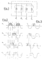
- Fig. 1 illustrates the motor of the invention having a biphase structure with four unipolar windings.
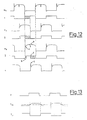
- the motor may operate as two single-phase in parallel, each of the four windings has conduction on 180° electrical (see Fig. 2).
- the biphase L.B. motors of this type usually conduct 90° electrical for each winding (see Fig. 3).
- the motor operating in biphase will thus develop about double maximum power if compared to the traditional utilization of same (conduction of about 90° electrical).
- the embodiment (wire section, number of turns of M1, M3 (two windings/unipolar phases of the first single-phase circuit realized in the motor) may be different from M2, M4 (the other two windings/unipolar phases of the second single-phase circuit realized in the motor and wound rotated of 90° electrical with respect to the first one).
- This motor is that three working speeds may be obtained (for the above mentioned loads) with power drive components always operating in saturation and not in "PWM” (pulse width modulation) or in "linear".
- the above solution involves a minimum dissipated power on the dissipator with all the conditions of power/speed mentioned; an advantage on operating costs is derived and on the possibility to realize smaller motor/electronic units offering higher performance with respect to known solutions.
- said known solutions may realize different speed either with highly dissipating "linear” control, or in "PWM” which is electrically and sometimes mechanically noisy, and in any case more expensive and more dissipating for the power components.
- the ratio AC/DC in particular, must be realized as a compromise between the following opposed requirements:
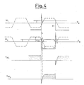
- a circuit for the quick "current detection” is obtainable as when connecting two resistances in differential for each of the two phases, that is at the two unipolar windings, (M1 and M3 are wound in the opposite sense giving E induced equal and opposite) a V c proportional to R m i m which follows i m is obtained, as RC time constant is very low with respect to the duration of each half period of i (see Fig. 5).
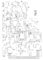
- Motor block 10 consists of four windings and a biphase structure, that is two pairs of windings each representing one of the two phases of the biphase. Each phase is made of two unipolar windings wound in the opposite direction to each other, each covering a half wave of the phase.
- the second block 11 may be called motor-sensors. Said block 11 has the task of gathering a set of information from the phases M1, M2, M3 and M4 of the motor 10, that is processings will be carried out on the wave forms at the end of each phase.
- a speed detection logic 12 is in block 11, and said logic will obtain speed information from the above wave forms.
- a logic 13 for the detection of motor current and temperature through Ri drop on each motor winding is located in block 11. Said logic 13, contained in the motor-sensors block 11, has the task of transmitting this information to the logic of other blocks.
- ri The drop of ri is intended as product Ri in which both the information of i - if R is deemed constant - and the temperature information are contained, as the resistance of the motor increases with temperature increase; thus, with equal i, the product Ri will increase and said signal will also increase. Both values are interesting for the protection of the motor: the current circulating in it and its temperature, so product Ri is a good indication.
- Motor-sensor block 11 also contains a logic for the detection of the rotor 14 position. Wave forms on M1, M,2 M,3 M4 are processed by said logic which gives signals to a successive block; from said signals a useful information on the rotor position is obtained, for the further driving of the switchings in the right sequence.
- An advance circuit for the high efficiency of the motor and transient suppression 15 is also contained in the motor-sensors block 11. Said circuit utilizes the information deriving from the speed detection logic 12 and said signal is carried back to drive the logic for the detection of the rotor position 14 to correct the phasing of the output signals and to give an advance to switchings. It will simultaneously generate a passive filter on switching transients.
- the output signal of speed detection logic 12 will also be used for other logics on successive blocks.
- a further block 18 may be called starting and driving logic: it consists of a unidirectional rotation logic and digital filter of transients 16. Said logic processes the signals deriving from the logic for the detection of rotor position 14 - which is in the motor-sensors block 11 - utilizing a latched logic (logic intended as logic circuit) and lets out driving signals of the various phases from its block, thus avoiding the motor to run in the unwanted direction; in other words, it enables the passage of logic signals if the rotor is running in the right direction, whilst it plugs the motor if the rotor is running in the wrong direction.
- a latched logic logic intended as logic circuit
- Said logic rotation block 16 also contains a digital filter logic of all transients that may arrive from the switching of the previous block, as the signals proceeding from M1, M2,M 3, M4, and passing through the logic for the detection of the rotor 14 position contain spurious signals for the effect of the switchings.
- the dynamic unidirectional logic 16 before driving the power transistors, goes through a starting oscillator 17; said oscillator is necessary in this system because it controls that one of two phases in random mode be set ON/OFF, instead of the Hall probes which would communicate to the circuit the phases to be switched on and in what sequence. The above is done to shake the motor position and with such movement to permit the generation of signals on M1 , M2, M3, M4 which may then be read in the logic and then begin the right phasing of the switchings on.
- the above described logics for the right phasings will enter in operation and the starting oscillator 17 will be locked in the frequency of the main drive and will not operate as an oscillator any more; said oscillator will only operate as such with still motor; as soon as the system starts and performs the lock-in, the oscillator is at lock-in on the driving frequency.
- the driving logic 18 contains a starting medium logic 19.
- the motor operates with current limitation, that is if instructions to run at very low speed would be given in input, it is necessary that the motor start with a rather high torque because this is the market requirement; if inconveniences may occur, like ice in the fan, to procure small friction static torque, the motor will start with high torque; said starting medium logic 19 feels the signal deriving from the speed detection logic 12 and if the motor runs under a certain speed it drives, with a signal of current limiters 20, so that a high value of current that can be defined by the electronic drive goes through the four windings thus realizing an INPUT bypass and starting the motor at high rating, even if the Input control indicates low rating.
- this block consists of power components 22, which may be four power Darlington or four MOS; the circuit for the driving of power components gives a proportional signal to the input and this will be either a speed or a torque check; circuit 20 will drive the power components 22 in linear. Said circuit 20 which drives the power components in linear is in turn checked by the driving logic of OFF states 23, for the selection of the power transistors to be driven in linear in the required way.
- Said logic 23 will alternatively switch off one or the other winding and thus one or the other component executing the current limitation control of the power components.
- Block 24 is called motor protection and electronics. It comprises a protection of the motor 25 and a protection of the electronic drive 25′.
- the motor protection block 25 gathers a set of information in INPUT and, as can be noted in the diagram, a set of information from various levels.
- oscillator 25 It fundamentally consists in an oscillator having a short ON period and a very long OFF period, the latter one taking place in case the system finds that the motor current has overcome a level called "warning level"; after some time an integrator feels the signal that said level has been overcome, said oscillator 25 keeps the motor ON for one or two seconds and OFF for some fifteen seconds allowing to cool and then tries again the starting system.
- the circuit of the motor protection 24 is in fact a rather sophisticated device: it is able to get various types of information as current level and fan speed.
- the speed signal reaches it as an information, as the description follows, said information is utilized also regarding the fan speed.
- the last block 26 is input block. It consists of only one control input, potentiometer 27, because 28 is an input which aids the protection circuit and may be considered an optional; the latter one in any case is not a real control input but a setting of the desired protection threshold 32.
- Block 26 contains the ON/OFF logic 29 which feels the real input signal and if said signal is lower than the minimum threshold, for instance lower than 0.6 volt, it takes it as a signal to switch off the entire module, in fact it switches off the entire circuit. If above mentioned signal is higher than 0.6 the block sets ON and block 30 enters in operation; said block performs various functions, according to how the components and the pins of the integrated circuit are connected. Said block 30 may perform a two fixed speed checks, a continuous speed check and a continuous torque check depending on the position of the value of the signal given in input.
- the following subblocks may be located in the motor-sensors block 11 (Fig. 7): logic for the current detection and motor temperature 13, logic for the detection of rotor position 14, advance circuit for motor high efficiency and transistor suppression 15, speed detection logic 12.
- One of the main features of this motor is to have two windings wound in the opposite direction for each phase. Said feature is such that, if the signals M1, M3 are taken back through the potential divider R18, R20, the signal which will result from their sum is the signal Ri of the phase which is conducting. Instant by instant, in fact, both for M1 and M3 the e.m.f. in the two phases is always opposite in sign; the two Es will give a null signal (see Fig. 5).
- Block 14 consists of four comparators OA3 , OA4 , OA5 , OA6 having analog input signal M1, M2, M3, M4 and giving square wave output with state passage in correspondence with passage of M1, M2, M3, M4 for the level established by the potential divider R2, R3 of block 15.
- the detection on block 14 is then carried out on zero established by said potential divider R2, R3.
- the signals that can be utilized on the successive logic are 1, 2, 3 and 4 so the block 14 comparators have been connected to avoid to insert reversers to obtain the signals 3 , 4 .
- Block 15 has diodes D1, D2, D3, D4 through which a condenser C1 is reached which has the task of absorbing the switchings that are never simultaneous, during said transistors. Said block 15, apart from the task of filtering said extra voltages through C1, also has the task of detecting the value of E with respect of V B for each phase as said signal is utilized to bias circuit 14, already examined, through resistances R2, R3 , giving it a variable reference with the motor speed.
- the signal in output from D1, D2, D3 and D4 will be made of a transient of the switchings and of e.m.f. signal which will alternatively be present on one of the two phases.
- Said signal, referred to V B will be attenuated with respect to V B in ratio R4 / (R1 + R4) where said attenuation will be set up motor by motor depending on the desired advance on switching.
- the attenuated signal in the ratio R4 / (R1 + R4 ) is the one appearing through the potential divider R2, R3 .
- the signal downstream of D1, D2, D3, D4 is filtered by the condenser C2 to give a continuous component representing a proportional signal to the speed of the motor.
- Block 12 gives SO signal in output; said signal is proportional to the motor speed and is obtained as difference between the signal at the end of the potential divider R2, R3 read by the operational OA1, and a signal V B read by the operational OA2, in order to cancel V B , also present on the potential divider R2, R3 from the differential utilization of the two operationals OA1, OA2 , which takes a signal only proportional to the speed of the motor on the resistance R6.
- the control circuit 21 (Fig.
- Block 20 has the task of transferring the information of signals CL 1,3 and CL 2.4 relating to drops Ri in the various windings to drive power components. As the circuits for signal CL 1,3 and CL 2,4 are identical, only the one relating to CL 1,3 will be examined.
- the signal CL 1,3 also contains an "error" signal due to the fact that the windings M1, M3 are referred to V B feeding so that a variation in the feeding voltage is carried over on the potential divider R18, R20 (see above), thus giving in CL 1,3 a signal indicating the feeding voltage variation.
- the resistance R40a signal is generated, proportional to the difference between CL 1,3 and V B excluding this information which is not pertinent with the required drop Ri.
- the signal on R40 goes to an amplifier OA11 which, with its output by means of a power amplification expressed by transistors TR12 TR14,drives in linear mode the respective power transistors of the windings M1M3.
- Said approach for the linear drive of the motor through a current control not only gives the best dynamic answer of the speed control system, as it is known by automatic controls, but, as a collateral performance, also "flattens" the current wave form in the windings giving a current wave form practically in d.c. line, with a minimum harmonic content and reducing to the minimum electrical and mechanical noise.
- the drive through OA11 is carried out through resistances B56, R58.
- Circuit 20 also contains signals SA and 2SC which, through the logic shown in drawings, switch off the two power transistors; said transistors drive M2 and M4 setting the transistors TR10and TR11 ON. Two of the four windings representing one of the two phases may thus be switched off, and the motor will run in single-phase.
- Logic 23 with the signal OFFL sets ON the four transistors TR8, TR9, TR10, and TR11 and switches off all the power transistors, whilst D 1,3 and D 2,4 that are logic signals enabling the switching on of the power transistors, switch on and off the various TR8, TR9, TR10 and TR11 to set the power transistors ON in the desired logic sequence.
- D 1,3 and D 2,4 that are logic signals enabling the switching on of the power transistors, switch on and off the various TR8, TR9, TR10 and TR11 to set the power transistors ON in the desired logic sequence.
- the first input AI is sent to an amplifier with hysteresis OA13which refers input AI to a fixed threshold on diode D12.
- OA13 which refers input AI to a fixed threshold on diode D12.
- a change of state will occur, due to resistances R71and R74, in the operational output to give a consent signal to the entire module.
- Said ON-OFF signal will drive the block of logic 23, already described.
- a signal OFFL originates which is different from the previous one because it drives a different logic in OR with O6 with a signal deriving from the protection circuit MOP.
- the second block 30 features two distinct functions; one regards the handling of signal AI which through the operational OA14, gives output signals 2C and TC which are proportional to the driving input.
- the operation OA14 may be embodied in different ways as for example those clearly illustrated in Fig. 9a-9f wherein the circuit of Fig. 9a performs a torque control, whilst the one of Fig. 9b carries out a speed control, and the circuit of Fig. 9c a two speed control with sensor NTC; the circuit of Fig. 9d is like the one of 9a but has an NTC input; the circuit of Fig. 9e is like of one of 9b with NTC input and the circuit of Fig. 9f is like the one of 9c with a three states input to handle ON-OFF and two speeds.
- the other part of block 30 linked to the signal SA sets the transistor TR16 ON which forces the output of the feedback amplifier employing the operational OA14 to the maximum possible level and limited by zener DZ whatever the AI output.
- the signal SA is only present at the moment of the motor start, and it disappears when the minimum level of the preset speed is reached, the presence of 2 SC and TC at the maximum of their value at the start is due to the fact that the start of the motor is always required with the maximum torque. This to avoid problems at the start of the motor due to accumulated dirt or frost.
- Signal TC is used for the continuous current control in circuit 21 whilst signal 2SC is used when the application with controlled motor on one or both phases is desired.
- the third circuit 32 generates a signal PM which communicates to block 25 that the protection circuit has entered in operation.
- Signal PM will exist, that is it will be in state 1, when one of the inputs PL1, PL2 through the operational OA15 OA16 (the one of the highest value) will communicate to the OA17 input a higher level than the one present at the other OA17input.
- Said level PL1, PL2, as mentioned, is proportional to the current in the phases. In other words, at the + input of OA17 the higher current level of each of the four windings will appear.
- On the - side of OA17 two types of signals may appear: one is SO, proportional to the motor speed, and another one derives from the potential divider R114, R115 that may be prefixed from the exterior.
- the output 1 from OA17 will occur when the currents in the phases will overcome the level on the - side of OA17 for each value of SO and prefixed threshold given by R114, R115.
- Said condition that may be handled motor by motor thanks to the potential divider, provokes the detection of a danger condition, which is different depending on the speed levels of the motor, as with equal current in input, the threshold of the comparation of current signals varies with speed through the SO signal.
- the motor and its electronic drive in fact, are cooled by the rotation speed of the motor, so higher current levels with higher speed are allowed without this being a danger condition.
- the low speed condition with high current levels instead is emphasized by the fact that with the lowering of SO the threshold for the comparation of current levels is lowered.
- the block for the motor protection and electronics 24 comprises (see Fig. 10) a block for the electronics protection 25′, its input being V B filtered through R84and the condenser C 9.
- V B generates a +Vcc feeding available to the electronic drive regulated by zener DZ2 and by transistor TR18.
- a resistance R93 which, in normal operating conditions is configurated to have a lower drop at its ends than the voltage to which the emitters TR20, TR21 , TR23 , TR24 are biased through the potential divider R88, R89 .
- V B voltage adjuster generating a more or less constant Vcc for the electronic drive.
- V B overcomes a prefixed level
- the transistor TR18 will have to absorb ever more current as Vcc tends to remain constant. Said current will generate an ever increasing drop on R93until it overcomes the bias threshold of the emitter of TR20, TR21, TR23, TR24 setting them ON.
- the second block 25 is substantially a relaxation oscillator driven through TR17, TR19, TR22and through signals SA, PM and ON-OFF generating an output signal MOP utilized by logic 29.
- the signal ON-OFF through TR22 will enable the oscillator to operate when the module is operating and will keep the condenser grounded if the module is off.
- TR17 instead is driven by PM, SA and MOP, and when it is kept ON it switches off TR19, keeping the base grounded, thus the condenser C10of the oscillator will be enabled to oscillate so the oscillator will begin to give a square wave MOP signal as drive signal of ON OFF protection states.
- the MOP signal is carried back to the input through R87 to avoid that when the protection circuit switches off the power components, said signal disappears at PM or SA input re-enabling the operation of the oscillator.
- the electronic drive must be OFF because it is protected, through the MOP signal and the resistance R87, TR17is being kept ON so that the oscillator is not disturbed during the entire protection phase.
- ON and OFF time of the oscillator are different, as ON time lasts a few seconds with an OFF time five-six times higher; the mean value of ON time must be very small so that the mean heating of the motor be lower than heating in the normal operating conditions. No thermal damages occur to the motor thanks to the ratio between low ON and high OFF time.
- the motor will try to restart to each cycle and this will occur if the impediment has been removed; if not, the oscillator will continue to oscillate keeping a non dangerous overvoltage and overcurrent condition.
- the charge and discharge resistance of C10 is splitted in a R95 to obtain an ON time different from an OFF time; said R95 in one direction is in parallel with R96 when the condenser is charged, whilst in the other direction R96 will only operate because diode 16 will not allow R95to operate; consequently charge and discharge times are different and, as mentioned before, generate different ON and OFF times.
- a possible driving logic for M1 can be observed (the drive of M3 will simply be the negated of the driving signal of M1 as the required feeding of M1 and M3will be at 180° electrical); said driving logic is 1 2 + 3 , that is "OR” between signal “ 3 " and “AND” of signal "1" and " 2 ".
- M1 and M3 must be at 180° and in phase with the respective e.m.f., it can be seen that M1 must be "ON" until a positive e.m.f. is read on M3 , that is a higher V B and in particular at the level established by the reference threshold, thus generating 3 high.
- AND 1 2 r is extended over the transient on " 3 " deriving from switchings in the windings M2 /M4 , already described.
- Suffix r has been added to " 2 " to indicate such shifting operated on signal 2 .
- the generation of a driving sequence (that may be followed at the output of gate A7 ), only if the rotation is the right one, has been obtained with the "block” utilizing the gates A3, I2, I3, A4, A7.
- Said circuit has the purpose of carrying out "AND” between the signals “1” and “ 2 " only if signal “1” in input at A3 arrives after the signal " 2 " r in input at A4 .
- the sequence is correct (Fig. 12) the signal “ 2 " r arrives before, and we will get at circuit input the situation as in the following Table: Signals "before” level “after” level “1” 0 1 " 2 r " 1 1 A7 0 1
- Signal 0 at input of A3 staticizes the output of A4 at level 1. It may easily be seen that the output of A4 remains in said state also when the input "1" goes from level 0 to level 1. When this occurs the output of AND A7 will go to 1, that is the block will have performed AND of signals "1" and " 2 ".
- Gate 04 has been added to the circuit with the purpose of making the driving logic insensible to any type of disturbing signals and operating only in case of correct rotation; said gate has the purpose of creating a latch in the output driving signal at A7 acting in that way as a filter with respect to transients present on the input "1" when the output of A7 level has reached level 1.
- Gates A1 and O2 realize "OR" of 1 2 r with 3 only if output of A7 is 1, which occurs only if the rotation direction is the right one.
- Block 19 is substantially an hysteresis circuit comparing the speed signal SO to preset thresholds.
- SA output signal will be "high" when the speed is under a preset level and normally corresponds to a speed value which is a small percentage of working speed. This logic serves to discriminate the starting transient from the speed condition.
- Block 17 consists of a relaxation oscillator of known type and realized by operational OA10 and by resistances R34, R35, R36, R37. It is inserted on the driving line D 1,3 and is characterized in that it carries thresholds, among them the condenser C8 may oscillate alternately through resistance R33 from the state 0 or 1 of D1.
- R33, R34, R35, R 36 is such that for D1 constant (corresponding to a "reading" of still motor) the oscillator will oscillate on its own frequency changing alternately D 1,3 and thus in sequence switching on M1 and M3 ignoring the correct phase relationships. This will procure a casual movement of motor rotor which, generating e.m.f., will supply to the above described rotation logic the information to generate the correct signals on D1 from the synchronization point of view to obtain a rotation in the required direction.
- the state variations of D1 are such to condition the oscillator to lock in the frequency and the phase of D1. In other words, as regards state changes of D1 the signal D 1,3 in output from the oscillator will result exactly equal to D1.
- the above described synchronized oscillator is also characterized in that an operating lock logic is conditioned either by signal OFFL high with motor off, or through O1 , locked by logic A9, I6 which gives a high signal, thus a lock signal, if SA is high and the motor is running in the wrong direction, and so with 0 on D1 and alternating of 0 and 1 at the output of 0 4.
- This last solution is necessary to avoid that the oscillator generates undesired switchings on M1, M3 if a casual start in the wrong direction takes place.
Landscapes
- Engineering & Computer Science (AREA)
- Power Engineering (AREA)
- Control Of Motors That Do Not Use Commutators (AREA)
- Structures Of Non-Positive Displacement Pumps (AREA)
- Control Of Multiple Motors (AREA)
- Compressor (AREA)
Applications Claiming Priority (2)
| Application Number | Priority Date | Filing Date | Title |
|---|---|---|---|
| IT8767986A IT1211537B (it) | 1987-11-18 | 1987-11-18 | Motore a corrente continua senza spazzole per motoventilatori pompe ed altre apparecchiature similari |
| IT6798687 | 1987-11-18 |
Publications (3)
| Publication Number | Publication Date |
|---|---|
| EP0316716A2 true EP0316716A2 (fr) | 1989-05-24 |
| EP0316716A3 EP0316716A3 (en) | 1989-11-02 |
| EP0316716B1 EP0316716B1 (fr) | 1992-08-26 |
Family
ID=11306959
Family Applications (1)
| Application Number | Title | Priority Date | Filing Date |
|---|---|---|---|
| EP88118574A Expired - Lifetime EP0316716B1 (fr) | 1987-11-18 | 1988-11-08 | Moteur à courant continu sans balais pour ventilateurs de moteur, pompes et équipements similaires |
Country Status (6)
| Country | Link |
|---|---|
| US (1) | US5053686A (fr) |
| EP (1) | EP0316716B1 (fr) |
| AT (1) | ATE79991T1 (fr) |
| DE (1) | DE3874090T2 (fr) |
| ES (1) | ES2035218T3 (fr) |
| IT (1) | IT1211537B (fr) |
Cited By (6)
| Publication number | Priority date | Publication date | Assignee | Title |
|---|---|---|---|---|
| EP0481933A1 (fr) * | 1990-10-18 | 1992-04-22 | INDUSTRIE MAGNETI MARELLI S.p.A. | Circuit de régulation pour un moteur sans balais avec n phases |
| EP0685927A3 (fr) * | 1994-06-03 | 1996-02-07 | Bosch Gmbh Robert | Méthode de freinage pour un moteur synchrone inverse tournant actionné par un réseau à cc. |
| GB2314471A (en) * | 1996-06-19 | 1997-12-24 | Sunonwealth Electr Mach Ind Co | Drive circuit for a brushless motor |
| WO1999052201A1 (fr) * | 1998-04-07 | 1999-10-14 | Robert Bosch Gmbh | Procede et dispositif pour la commande d'un moteur polyphase a courant continu commute electroniquement |
| WO2001026211A1 (fr) * | 1999-10-01 | 2001-04-12 | Bitron S.P.A. | Dispositif de commande sans capteur pour moteurs sans balais a courant continu |
| CN1324799C (zh) * | 2004-06-03 | 2007-07-04 | 旺玖科技股份有限公司 | 低噪音直流马达驱动芯片 |
Families Citing this family (8)
| Publication number | Priority date | Publication date | Assignee | Title |
|---|---|---|---|---|
| US5744921A (en) * | 1996-05-02 | 1998-04-28 | Siemens Electric Limited | Control circuit for five-phase brushless DC motor |
| US5675464A (en) * | 1996-05-02 | 1997-10-07 | Siemens Electric Limited | Stall or reduced-speed protection system for electric motor |
| FR2764430B1 (fr) * | 1997-06-04 | 1999-07-23 | Mecagis | Procede de traitement thermique sous champ magnetique d'un composant en materiau magnetique doux |
| JP4680367B2 (ja) * | 2000-10-10 | 2011-05-11 | ルネサスエレクトロニクス株式会社 | ブラシレスモータ駆動回路 |
| US7412339B2 (en) * | 2002-05-24 | 2008-08-12 | Virginia Tech Intellectual Properties, Inc. | Method and apparatus for identifying an operational phase of a motor phase winding and controlling energization of the phase winding |
| JP2004201487A (ja) * | 2002-11-28 | 2004-07-15 | Nsk Ltd | モータ及びその駆動制御装置 |
| US8378618B2 (en) * | 2010-02-19 | 2013-02-19 | Sntech, Inc. | Systems and methods for controlling operations of a motor |
| EP3644493B1 (fr) * | 2017-06-21 | 2023-04-26 | Toshiba Mitsubishi-Electric Industrial Systems Corporation | Dispositif de démarrage de thyristor |
Family Cites Families (13)
| Publication number | Priority date | Publication date | Assignee | Title |
|---|---|---|---|---|
| CH475667A (de) * | 1968-10-24 | 1969-07-15 | Licentia Gmbh | Einrichtung mit einem über steuerbare Halbleiter gespeisten bürstenlosen Gleichstrommotor |
| FR2123928A5 (fr) * | 1971-02-05 | 1972-09-15 | Radiotechnique Compelec | |
| US4162435A (en) * | 1976-10-05 | 1979-07-24 | General Electric Company | Method and apparatus for electronically commutating a direct current motor without position sensors |
| US4424471A (en) * | 1978-11-30 | 1984-01-03 | Ford Motor Company | Electrical motor |
| US4355255A (en) * | 1979-08-28 | 1982-10-19 | The Singer Company | Brushless direct current motor and control therefor |
| US4403177A (en) * | 1981-08-17 | 1983-09-06 | Motorola, Inc. | Brushless three phase direct current motor control circuit |
| DE3331194A1 (de) * | 1983-08-30 | 1985-03-07 | Ebm Elektrobau Mulfingen Gmbh & Co, 7119 Mulfingen | Kollektorloser gleichstrommotor mit dreistraengiger, ungesehnter statorwicklung |
| US4641066A (en) * | 1984-10-04 | 1987-02-03 | Nippondenso Co., Ltd. | Control apparatus for brushless motor |
| US4656553A (en) * | 1986-01-21 | 1987-04-07 | Comair Rotron, Inc. | Electronically programmable universal brushless DC fan with integral tracking and locked rotor protection |
| US4678973A (en) * | 1986-10-07 | 1987-07-07 | General Motors Corporation | Sensorless starting control for a brushless DC motor |
| US4673849A (en) * | 1986-10-10 | 1987-06-16 | Allied Corporation | Permanent magnet motor closed loop restarting system |
| US4743815A (en) * | 1987-09-01 | 1988-05-10 | Emerson Electric Co. | Brushless permanent magnet motor system |
| US4912378A (en) * | 1988-07-21 | 1990-03-27 | Emerson Electric Co. | Third harmonic commutation control system and method |
-
1987
- 1987-11-18 IT IT8767986A patent/IT1211537B/it active
-
1988
- 1988-11-08 ES ES198888118574T patent/ES2035218T3/es not_active Expired - Lifetime
- 1988-11-08 EP EP88118574A patent/EP0316716B1/fr not_active Expired - Lifetime
- 1988-11-08 AT AT88118574T patent/ATE79991T1/de active
- 1988-11-08 DE DE8888118574T patent/DE3874090T2/de not_active Expired - Fee Related
-
1990
- 1990-04-25 US US07/514,194 patent/US5053686A/en not_active Expired - Lifetime
Cited By (7)
| Publication number | Priority date | Publication date | Assignee | Title |
|---|---|---|---|---|
| EP0481933A1 (fr) * | 1990-10-18 | 1992-04-22 | INDUSTRIE MAGNETI MARELLI S.p.A. | Circuit de régulation pour un moteur sans balais avec n phases |
| EP0685927A3 (fr) * | 1994-06-03 | 1996-02-07 | Bosch Gmbh Robert | Méthode de freinage pour un moteur synchrone inverse tournant actionné par un réseau à cc. |
| GB2314471A (en) * | 1996-06-19 | 1997-12-24 | Sunonwealth Electr Mach Ind Co | Drive circuit for a brushless motor |
| WO1999052201A1 (fr) * | 1998-04-07 | 1999-10-14 | Robert Bosch Gmbh | Procede et dispositif pour la commande d'un moteur polyphase a courant continu commute electroniquement |
| US6429614B1 (en) | 1998-04-07 | 2002-08-06 | Robert Bosch Gmbh | Method and device for controlling an electronically commutated polyphase D.C. motor |
| WO2001026211A1 (fr) * | 1999-10-01 | 2001-04-12 | Bitron S.P.A. | Dispositif de commande sans capteur pour moteurs sans balais a courant continu |
| CN1324799C (zh) * | 2004-06-03 | 2007-07-04 | 旺玖科技股份有限公司 | 低噪音直流马达驱动芯片 |
Also Published As
| Publication number | Publication date |
|---|---|
| EP0316716B1 (fr) | 1992-08-26 |
| DE3874090T2 (de) | 1993-03-18 |
| US5053686A (en) | 1991-10-01 |
| DE3874090D1 (de) | 1992-10-01 |
| IT8767986A0 (it) | 1987-11-18 |
| ES2035218T3 (es) | 1993-04-16 |
| EP0316716A3 (en) | 1989-11-02 |
| IT1211537B (it) | 1989-11-03 |
| ATE79991T1 (de) | 1992-09-15 |
Similar Documents
| Publication | Publication Date | Title |
|---|---|---|
| EP0316716B1 (fr) | Moteur à courant continu sans balais pour ventilateurs de moteur, pompes et équipements similaires | |
| US4535275A (en) | Brushless D-C motor system with improved commutation circuit | |
| US6097127A (en) | Permanent magnet direct current (PMDC) machine with integral reconfigurable winding control | |
| US4063135A (en) | Electric motor having controlled magnetic flux density | |
| JP2816387B2 (ja) | 電源装置 | |
| CA1221413A (fr) | Detecteur de diode tournante court-circuitee dans un moteur sans balais | |
| Erdman et al. | Electronically commutated dc motors for the appliance industry | |
| US3780363A (en) | Brushless dynamo electric machine, particularly electric motor | |
| US6307338B1 (en) | Electronically commutated motor | |
| US5117167A (en) | Commutating energy suppression circuit for an electronically commutated DC motor | |
| JPH04229090A (ja) | 反作用電動機の駆動用回路装置 | |
| US4139807A (en) | Rotor short-circuiting switch | |
| JP6390811B2 (ja) | モータ駆動装置 | |
| US4535274A (en) | Driving circuit for brushless D.C. motor | |
| US20070046248A1 (en) | System and method for controlling an induction motor | |
| Colby | Classification of inverter driven permanent magnet synchronous motors | |
| EP0387358A1 (fr) | Moteur a courant continu | |
| Hao et al. | Analysis of electrical faults for switched reluctance motor driver | |
| US3864605A (en) | Overload protection for miniature d-c motors | |
| WO2015098942A1 (fr) | Dispositif d'entraînement de moteur | |
| JP4590658B2 (ja) | 制御装置 | |
| JPH041571B2 (fr) | ||
| JP3365249B2 (ja) | モータ駆動装置 | |
| US20090224711A1 (en) | Rotating electrical machine with decoupled phases | |
| Nonaka et al. | Variable-speed control of brushless half-speed synchronous motor by voltage source inverter |
Legal Events
| Date | Code | Title | Description |
|---|---|---|---|
| PUAI | Public reference made under article 153(3) epc to a published international application that has entered the european phase |
Free format text: ORIGINAL CODE: 0009012 |
|
| AK | Designated contracting states |
Kind code of ref document: A2 Designated state(s): AT BE CH DE ES FR GB GR IT LI LU NL SE |
|
| PUAL | Search report despatched |
Free format text: ORIGINAL CODE: 0009013 |
|
| AK | Designated contracting states |
Kind code of ref document: A3 Designated state(s): AT BE CH DE ES FR GB GR IT LI LU NL SE |
|
| 17P | Request for examination filed |
Effective date: 19900125 |
|
| 17Q | First examination report despatched |
Effective date: 19910128 |
|
| RAP1 | Party data changed (applicant data changed or rights of an application transferred) |
Owner name: ELETTROVAGO S.P.A. |
|
| GRAA | (expected) grant |
Free format text: ORIGINAL CODE: 0009210 |
|
| AK | Designated contracting states |
Kind code of ref document: B1 Designated state(s): AT BE CH DE ES FR GB GR IT LI LU NL SE |
|
| PG25 | Lapsed in a contracting state [announced via postgrant information from national office to epo] |
Ref country code: SE Free format text: THE PATENT HAS BEEN ANNULLED BY A DECISION OF A NATIONAL AUTHORITY Effective date: 19920826 Ref country code: NL Effective date: 19920826 Ref country code: GR Free format text: LAPSE BECAUSE OF FAILURE TO SUBMIT A TRANSLATION OF THE DESCRIPTION OR TO PAY THE FEE WITHIN THE PRESCRIBED TIME-LIMIT Effective date: 19920826 Ref country code: BE Effective date: 19920826 Ref country code: AT Effective date: 19920826 |
|
| REF | Corresponds to: |
Ref document number: 79991 Country of ref document: AT Date of ref document: 19920915 Kind code of ref document: T |
|
| REF | Corresponds to: |
Ref document number: 3874090 Country of ref document: DE Date of ref document: 19921001 |
|
| ET | Fr: translation filed | ||
| ITF | It: translation for a ep patent filed | ||
| PG25 | Lapsed in a contracting state [announced via postgrant information from national office to epo] |
Ref country code: LU Free format text: LAPSE BECAUSE OF NON-PAYMENT OF DUE FEES Effective date: 19921130 |
|
| NLV1 | Nl: lapsed or annulled due to failure to fulfill the requirements of art. 29p and 29m of the patents act | ||
| REG | Reference to a national code |
Ref country code: ES Ref legal event code: FG2A Ref document number: 2035218 Country of ref document: ES Kind code of ref document: T3 |
|
| PLBE | No opposition filed within time limit |
Free format text: ORIGINAL CODE: 0009261 |
|
| STAA | Information on the status of an ep patent application or granted ep patent |
Free format text: STATUS: NO OPPOSITION FILED WITHIN TIME LIMIT |
|
| 26N | No opposition filed | ||
| REG | Reference to a national code |
Ref country code: CH Ref legal event code: PUE Owner name: ELETTROVAGO S.P.A. TRANSFER- BITRON S.P.A. |
|
| REG | Reference to a national code |
Ref country code: FR Ref legal event code: TP Free format text: CORRECTION |
|
| REG | Reference to a national code |
Ref country code: ES Ref legal event code: PC2A Owner name: BITRON S.P.A. |
|
| PGFP | Annual fee paid to national office [announced via postgrant information from national office to epo] |
Ref country code: GB Payment date: 19991112 Year of fee payment: 12 |
|
| PGFP | Annual fee paid to national office [announced via postgrant information from national office to epo] |
Ref country code: ES Payment date: 19991115 Year of fee payment: 12 |
|
| PGFP | Annual fee paid to national office [announced via postgrant information from national office to epo] |
Ref country code: CH Payment date: 19991126 Year of fee payment: 12 |
|
| PGFP | Annual fee paid to national office [announced via postgrant information from national office to epo] |
Ref country code: FR Payment date: 19991130 Year of fee payment: 12 |
|
| PGFP | Annual fee paid to national office [announced via postgrant information from national office to epo] |
Ref country code: DE Payment date: 19991230 Year of fee payment: 12 |
|
| PG25 | Lapsed in a contracting state [announced via postgrant information from national office to epo] |
Ref country code: GB Free format text: LAPSE BECAUSE OF NON-PAYMENT OF DUE FEES Effective date: 20001108 |
|
| PG25 | Lapsed in a contracting state [announced via postgrant information from national office to epo] |
Ref country code: ES Free format text: LAPSE BECAUSE OF NON-PAYMENT OF DUE FEES Effective date: 20001109 |
|
| PG25 | Lapsed in a contracting state [announced via postgrant information from national office to epo] |
Ref country code: LI Free format text: LAPSE BECAUSE OF NON-PAYMENT OF DUE FEES Effective date: 20001130 Ref country code: CH Free format text: LAPSE BECAUSE OF NON-PAYMENT OF DUE FEES Effective date: 20001130 |
|
| GBPC | Gb: european patent ceased through non-payment of renewal fee |
Effective date: 20001108 |
|
| REG | Reference to a national code |
Ref country code: CH Ref legal event code: PL |
|
| PG25 | Lapsed in a contracting state [announced via postgrant information from national office to epo] |
Ref country code: FR Free format text: LAPSE BECAUSE OF NON-PAYMENT OF DUE FEES Effective date: 20010731 |
|
| PG25 | Lapsed in a contracting state [announced via postgrant information from national office to epo] |
Ref country code: DE Free format text: LAPSE BECAUSE OF NON-PAYMENT OF DUE FEES Effective date: 20010801 |
|
| REG | Reference to a national code |
Ref country code: FR Ref legal event code: ST |
|
| REG | Reference to a national code |
Ref country code: ES Ref legal event code: FD2A Effective date: 20011214 |
|
| PG25 | Lapsed in a contracting state [announced via postgrant information from national office to epo] |
Ref country code: IT Free format text: LAPSE BECAUSE OF NON-PAYMENT OF DUE FEES Effective date: 20051108 |