EP0316794A2 - Etui pour dispositif auxiliaire - Google Patents
Etui pour dispositif auxiliaire Download PDFInfo
- Publication number
- EP0316794A2 EP0316794A2 EP88118809A EP88118809A EP0316794A2 EP 0316794 A2 EP0316794 A2 EP 0316794A2 EP 88118809 A EP88118809 A EP 88118809A EP 88118809 A EP88118809 A EP 88118809A EP 0316794 A2 EP0316794 A2 EP 0316794A2
- Authority
- EP
- European Patent Office
- Prior art keywords
- case
- aid
- storage container
- case according
- elastic
- Prior art date
- Legal status (The legal status is an assumption and is not a legal conclusion. Google has not performed a legal analysis and makes no representation as to the accuracy of the status listed.)
- Withdrawn
Links
- 238000000576 coating method Methods 0.000 claims description 7
- 239000011248 coating agent Substances 0.000 claims description 6
- 239000000463 material Substances 0.000 claims description 4
- 239000007779 soft material Substances 0.000 claims 1
- 239000011521 glass Substances 0.000 description 30
- 230000000694 effects Effects 0.000 description 4
- 239000000428 dust Substances 0.000 description 2
- 239000013013 elastic material Substances 0.000 description 2
- 238000003780 insertion Methods 0.000 description 2
- 230000037431 insertion Effects 0.000 description 2
- 229910000639 Spring steel Inorganic materials 0.000 description 1
- 238000005299 abrasion Methods 0.000 description 1
- 238000009825 accumulation Methods 0.000 description 1
- 239000006260 foam Substances 0.000 description 1
- 238000005187 foaming Methods 0.000 description 1
- 230000002035 prolonged effect Effects 0.000 description 1
- 239000007787 solid Substances 0.000 description 1
Images


Classifications
-
- G—PHYSICS
- G02—OPTICS
- G02B—OPTICAL ELEMENTS, SYSTEMS OR APPARATUS
- G02B23/00—Telescopes, e.g. binoculars; Periscopes; Instruments for viewing the inside of hollow bodies; Viewfinders; Optical aiming or sighting devices
- G02B23/16—Housings; Caps; Mountings; Supports, e.g. with counterweight
Definitions
- the invention relates to a case for aids, in which the aid or its storage container can be removed with a handle from the case or inserted into the case and the aid or its storage container is firmly attached to the inside of the case at least two points on the inside of the case .
- the bags are made of a flexible material with a soft inner surface. With them, aids that have a sensitive surface (e.g. hand magnifiers) are only insufficiently protected because, due to the flexibility of the bag material, local loads can easily occur. In addition, the bags do not give the aids a firm hold and when transporting the aids, sensitive surfaces can easily be damaged by abrasive effects on the inside of the bags.
- aids that have a sensitive surface e.g. hand magnifiers
- Cases are much more suitable for storing aids.
- the ability to rigidly design the cases can significantly improve protection against external mechanical loads.
- the aid In order to offer the aid a hold in the inside of the case, the aid is usually fixed with rigid bodies, which prevent the aid from being quickly removed from the case.
- these cases are usually provided with closures, which wear out quickly if they are insufficiently solid and therefore expensive and also do not allow easy handling.
- the determination is made via a friction between the inside of the case and certain surfaces of the aid. Even if this friction usually does not occur between the inside of the case and the sensitive surfaces of the aid in order to prevent their damage, contact between them can usually not be ruled out and thus damage to the sensitive surfaces of the aid. In addition, the electrostatic charge caused by the friction very quickly contaminates the case or the aid. Furthermore, the elastic covering attached to the inside of the case tends to become permanently deformed due to the continuous load after prolonged use, so that it is a matter of time before the aids in the case no longer have a firm hold. If the aids are often inserted into the case in the same way, it is difficult to avoid signs of abrasion on the aids.
- the object of the invention is to obtain a case for aids or storage containers, which ensures the aid or a storage container, even if it has sensitive surfaces, a secure hold without straining the sensitive surfaces and which has a wear-resistant, easily detachable closure.
- magnifying glasses have a firm hold in the cases without the magnifying lens having to be in contact with the inside of the cases and the elastic insert rarely, namely when removed or inserted, in a deformed Condition.
- This relaxation of the holding element of the case ensures a long life of the insert and thus a long usability of the case.
- the magnifying glass holder has a firm hold in the case of hand-held magnifiers, without the hold being deformed, e.g. Friction that is generated.
- the hold is realized by a cavity in the case adapted to the shape of the lens frame, certain areas being elastic in order to enable quick and easy removal or a quick and easy insertion of the hand magnifier into the case.
- the walls of the case are inelastic as possible. This ensures that the case can be exposed to strong mechanical loads in use without damaging the hand magnifier.
- the inelastic outer walls are intended to prevent the case from coming into contact with the sensitive surfaces and from transferring a lateral pressure to the other sides of the aids, which could also lead to tension on the sensitive surfaces.
- the movement of the aid in the case should be as easy as possible, i.e. the inside of the case should offer as little resistance as possible to movement of the aid.
- a positive development of the invention is therefore to provide the inside walls of the case with a coating that is as smooth as possible or a covering that is as smooth as possible. This also minimizes dirt and dust accumulation inside the case due to electrostatic build-up.
- the elastic insert can advantageously consist of the same elastic material of the soft elastic and shock-absorbing coating of the outer contact surfaces of the case.
- the elastic insert can also consist of an elastic base body on the hard walls, which can optionally be covered with a smooth coating or the smooth covering of the inner walls of the case. Any other realization of the insert is also to be used in the same way for the invention, as long as the insert is resilient and preferably has a surface that is as smooth as possible.
- the invention can be implemented in cases which correspond to the shape of hand-held magnifiers and enclose them in a form-fitting manner, so that the aid takes up as little space as possible in the case. However, it can also make sense to give the case a different outer dimension that does not correspond to the shape of the aid (e.g. better stackability for storage purposes, etc.). Each of these shapes has special advantages in itself.
- the elastic support or supports are located on the circular circumference. It is advantageous to provide an elastic support on each side of the removal opening in the interior of the case, although even an elastic support on the inside of the removal opening limitation is sufficient for a secure hold of the aid in the case.
- the interior of the case in such a way that the lower circular half of the case corresponds exactly to the shape of the aid to be accommodated and to extend this semicircle with two almost parallel, slightly inclined straight lines.
- the elastic inserts can then be adapted and fastened to these almost parallel straight lines so that their relaxed shape corresponds as exactly as possible with the aid to be held. If the aid is to be removed from the case, the elastic inserts can deform and be pressed into the space which is between the almost parallel, slightly outwardly inclined straight line and the corresponding exactly parallel straight line.
- the elastic inserts can also be used to fix the aid handle. For this purpose, it is advantageous to attach them to each lid on both sides of the handle. The more elastic the cover can move outwards, the less elastic the inserts can be. A particularly advantageous use of this invention consists in the possibility of being able to use the elastic inserts at the same time for holding the aid and for fixing the aid handle.
- FIGS. 10 and 11 The explanation of the invention on the basis of magnifying glass cases is in no way intended to limit the scope of the invention only to this.
- the invention can be used in all those areas of application in which an object is inserted into another object and an easy solution to the connection of these two bodies is sought under a predetermined load. This is exemplified by FIGS. 10 and 11.
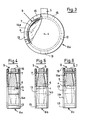
- Fig. 1 is a round, form-fitting hand magnifier case (8) in Supervision shown.
- the handheld magnifier (9) consists of a handle (5), a lens holder (7) and a lens (6) with its center (4).
- the hand-held magnifier (9) lies in the lower part (ie that part of the lens which, seen from the handle (5), lies below the center point (4)) firmly against the side wall (2) of the case (8) along a semicircle.
- the side walls (2) on both sides of the stem (5) center (4) connecting line run obliquely outwards. At the end of the side walls (2) they have such an elastic insert (3) that the elastic insert (3) comes into contact with the lens frame (7) again.
- the space between the two drawn-in auxiliary lines (10a, b) is occupied by the lens frame (7).
- the protruding elastic inserts (3) at the end of the side walls (2) must deform so that this space is available to the lens frame (7) when it is pulled out.
- the elastic insert (3) in the way is printed in the empty space between the beginning of the insert and the beginning of the round half-shell. The easiest way to achieve this is with an elastic, deformable insert (3).
- the degree of elasticity determines the force that is required to separate the magnifying glass (9) from its case (8).
- FIG. 2 shows the side view of FIG. 1.
- the magnifying glass (9) with the handle (5), the lens holder (7) and the lens (6) is in her case (8).
- the two case covers (1a, 1b) limit the magnifying glass (9) to the side here, while the side walls (2) are hardly visible from this view.
- the elastic inserts (3) of the side walls (2) are located at the end thereof above the center of the lens (4).
- the inside of the two case covers (1a, b) are provided with a smooth, fabric-like cover (11), while the outside of the two case covers (1a, b) have an elastic, shock-absorbing cover (12).
- Fig. 3 is also a round magnifying glass case (8a) can be seen, which this time does not enclose the lens form-fitting, but has a fixation (15) of the stem (5).
- the lens holder (7) lies in the lower part (below the center point (4) from the stem (5)) on three magnifying glass contact surfaces (13). Since all three supports (13) (there may also be two magnifying supports (13) which, together with the fixing (15) of the stem (5), divide the pitch circle described by the lens (6) into three sectors of equal size) on one Are semicircle, a fixed position of the magnifying glass (9) in the case (8a) is only ensured by the handle fixing (15) on both sides of the handle (5).
- the covers (14a) of the case (8a) limit this laterally, the magnifying glass (9) not reaching to the side edge here.
- the connection of the two side covers (14a) is made by the three magnifying glass supports (13), since the two fixings (15) are each only attached to one cover (14a).
- the upper part of the cover (14a) can yield elastically when the lens is removed or inserted into the case.
- Fig. 4 the case (8) is shown in a side view.
- the definitions (15) are located on both lids (14a) of the case (8a), a lateral attachment of a definition (15) to only one lid (14a) would be sufficient to hold the magnifying glass (9) securely in the case (8a) .
- the fixings (15) were attached to the inside of both covers (14a). The space between the individual magnifying glass supports (13) is left open in this case (8a).
- the stipulations (15) are designed such that they have a flatter wedge shape on the outside than on the inside in order to ensure that the magnifying glass (9) is securely inserted into the case (8a), on the other hand the magnifying glass (9) in the case (8a) to give a secure hold. Due to the elasticity of the two covers (14a), the fixings (15) can remove the magnifying glass (9) when it is removed or pushed in without it being able to hit the lens (6) after passing through the lens holder (7).
- Fig. 5 the only difference from Fig. 4 is that the space between the magnifying glasses (13) has been closed. This closure of the intermediate space can leave the space between the lens frame (7) and the case (8a) free, but there is also the possibility of completely closing this space up to the lens frame (7).
- Fig. 6 the difference to Fig. 5 is that the two specifications (15) are supplemented by two further specifications (15a). Between these definitions (15, 15a), the lens frame (7) is now defined by the distance between the definitions (between 15 and 15a).
- Fig. 7 is a case (8d) for a round hand magnifier (9) shown, which has a rectangular outer shape and has a fixing (15b) of the magnifying stem (5).
- the inside of this case (8d) corresponds essentially to the case (8) from FIGS. 1 and 2.
- the only differences are in the elastic full foaming of the area (17) between the lens frame (7) and the stiffened outer surfaces (16) of the Cases (8d). Due to the full foam (17), the area around the elastic inserts (3a) is elastic enough to give way to the deformations that occur during handling (removing and inserting) the magnifying glass (9) by the movement of the lens frame (7) in such a way that an empty space in contrast to Fig. 1 here with the elastic inserts (3a) need not be provided.
- the elastic inserts (3a) can consist of the material of the fully foamed area (17).
- the resilience of the area (17) fully foamed with elastic material is a feature for the secure hold of the lens. Therefore, it should not be too high.
- the stems (5) of the magnifying glass (9) can be brought into a defined position by means of the definitions (15b).
- These definitions (15b) can have the shape shown in FIG. 7 and are only outside the circle of the lens frame, or, according to FIG. 6, on both sides of the lens frame (7) of the magnifying glass (9) located in the case (8d) be attached.
- the elastic inserts (3a) should be located above the center of the lens (4) in order to hold the magnifying glass (9) through their wedge effect.
- FIG. 8 shows a case (8f) for a rectangular hand magnifier (9a).
- This rectangular hand magnifier (9a) has a handle (23) on the lens holder (18) of the lens (24).
- the magnifying glass (9a) is held on the boundary sides (20, 21) of the case (8f), on which it lies well. Nevertheless, there is so much space between the lens frame (18) and the lens (24) to the boundary sides (20, 21) that the magnifying glass (9a) is not held in the case (8f) by friction. Rather, the magnifying glass (9a) is held in the case (8f) by the fixing (22) above the lens frame (18).
- the magnifying glass (9a) is here positively housed in the case (8f).
- the innovation also allows the handle (23) to be extended and thus to protrude from the case (8f).
- Fig. 9 the case (8f) of Fig. 8 is shown from the side.
- the elasticity of the side walls (19) of the case (8f) is so great here that no extra space has to be taken into account here either for the determinations (22).
- FIGS. 10 and 11 show an example of the use of the case (8) from FIGS. 1 and 2 as a storage container for other aids (26), the shape of which resembles the shape of a hand magnifier.
- the case is a box-shaped body (26) for storing the body.
- the box-shaped body (26) has the same round outer shape (25) of magnifying glass frames, but has a bottom (28). As a result, other objects can be stored in the interior (29) of this box-shaped body (26).
- the box-shaped body (26) can be removed from the case (8) using a handle (27).
- the case can have the inner and outer covers (11 and 12) described in Fig. 2.
Landscapes
- Physics & Mathematics (AREA)
- Astronomy & Astrophysics (AREA)
- General Physics & Mathematics (AREA)
- Optics & Photonics (AREA)
- Lenses (AREA)
- Details Of Rigid Or Semi-Rigid Containers (AREA)
- Purses, Travelling Bags, Baskets, Or Suitcases (AREA)
- Packaging Frangible Articles (AREA)
Applications Claiming Priority (2)
| Application Number | Priority Date | Filing Date | Title |
|---|---|---|---|
| DE8715127U DE8715127U1 (de) | 1987-11-13 | 1987-11-13 | Etui für Hilfsmittel vorzugsweise Handlupen |
| DE8715127U | 1987-11-13 |
Publications (2)
| Publication Number | Publication Date |
|---|---|
| EP0316794A2 true EP0316794A2 (fr) | 1989-05-24 |
| EP0316794A3 EP0316794A3 (fr) | 1990-05-16 |
Family
ID=6814091
Family Applications (1)
| Application Number | Title | Priority Date | Filing Date |
|---|---|---|---|
| EP88118809A Withdrawn EP0316794A3 (fr) | 1987-11-13 | 1988-11-11 | Etui pour dispositif auxiliaire |
Country Status (3)
| Country | Link |
|---|---|
| EP (1) | EP0316794A3 (fr) |
| JP (1) | JPH01124121U (fr) |
| DE (1) | DE8715127U1 (fr) |
Family Cites Families (3)
| Publication number | Priority date | Publication date | Assignee | Title |
|---|---|---|---|---|
| GB302494A (en) * | 1927-12-10 | 1928-12-20 | Harold Thomas Shakespeare | A new or improved holder or clip for cups and like articles |
| GB679212A (en) * | 1950-01-17 | 1952-09-17 | Lucas Ltd Joseph | Improvements relating to pocket lenses |
| US2644471A (en) * | 1950-02-11 | 1953-07-07 | Howard S Brown | Coin holder |
-
1987
- 1987-11-13 DE DE8715127U patent/DE8715127U1/de not_active Expired
-
1988
- 1988-11-10 JP JP14604188U patent/JPH01124121U/ja active Pending
- 1988-11-11 EP EP88118809A patent/EP0316794A3/fr not_active Withdrawn
Also Published As
| Publication number | Publication date |
|---|---|
| EP0316794A3 (fr) | 1990-05-16 |
| DE8715127U1 (de) | 1988-01-07 |
| JPH01124121U (fr) | 1989-08-23 |
Similar Documents
| Publication | Publication Date | Title |
|---|---|---|
| DE2411495C3 (de) | Behälter mit Stülpdeckel und Schnappverschluß | |
| DE69414397T2 (de) | Einsatz für einen müllbehälter | |
| EP0178406A1 (fr) | Ensemble fourreau pour stylographes | |
| DE202013002265U1 (de) | Behälter zur Aufnahme von Kleinteilen | |
| EP0274742B1 (fr) | Récipient en matière plastique | |
| EP2905244B1 (fr) | Couvercle pour un récipient collecteur et récipient collecteur, en particulier collecteur de déchets, doté d'un couvercle | |
| DE102009011435B4 (de) | Griffelement für Sterilisierbehälter | |
| DE2745004C2 (de) | Spender für stabförmige Kleinteile | |
| DE8715127U1 (de) | Etui für Hilfsmittel vorzugsweise Handlupen | |
| DE4005573A1 (de) | Box fuer schraubendrehereinsaetze | |
| DE8620396U1 (de) | Kassette zur Aufbewahrung von länglichen Gegenständen | |
| DE2835165C2 (de) | Behälter zum Aufbewahren von fotografischen Bildern | |
| DE4224217C2 (de) | Behälter | |
| DE102013214791A1 (de) | Spenderbox | |
| DE2706062A1 (de) | Behaelter fuer zahnbuersten | |
| DE3621341A1 (de) | Behaelter | |
| DE19721943A1 (de) | Behälterverschluß und dazu ausgewählte Behälter | |
| DE60210320T2 (de) | Aufbewahrungsbehälter | |
| DE202025102478U1 (de) | Kastenartiger Gegenstand zum einfachen Austauschen von Typenschildern | |
| DE9108514U1 (de) | Haltevorrichtung | |
| DE8324492U1 (de) | Schuhcremedose mit abnehmbarem Verschlussdeckel | |
| DE20012495U1 (de) | Transportbehälter | |
| DE1536279C (de) | Aufnahme und Transportbehälter fur Uhrfedern | |
| DE9303300U1 (de) | Transport- und Lagerbehälter | |
| CH634270A5 (en) | Dispenser for small items |
Legal Events
| Date | Code | Title | Description |
|---|---|---|---|
| PUAI | Public reference made under article 153(3) epc to a published international application that has entered the european phase |
Free format text: ORIGINAL CODE: 0009012 |
|
| AK | Designated contracting states |
Kind code of ref document: A2 Designated state(s): CH DE FR GB IT LI |
|
| PUAL | Search report despatched |
Free format text: ORIGINAL CODE: 0009013 |
|
| AK | Designated contracting states |
Kind code of ref document: A3 Designated state(s): CH DE FR GB IT LI |
|
| 17P | Request for examination filed |
Effective date: 19901012 |
|
| 17Q | First examination report despatched |
Effective date: 19920129 |
|
| STAA | Information on the status of an ep patent application or granted ep patent |
Free format text: STATUS: THE APPLICATION IS DEEMED TO BE WITHDRAWN |
|
| 18D | Application deemed to be withdrawn |
Effective date: 19940126 |