EP0316824A2 - Rohrförmiger Pflugrahmen - Google Patents
Rohrförmiger Pflugrahmen Download PDFInfo
- Publication number
- EP0316824A2 EP0316824A2 EP88118891A EP88118891A EP0316824A2 EP 0316824 A2 EP0316824 A2 EP 0316824A2 EP 88118891 A EP88118891 A EP 88118891A EP 88118891 A EP88118891 A EP 88118891A EP 0316824 A2 EP0316824 A2 EP 0316824A2
- Authority
- EP
- European Patent Office
- Prior art keywords
- plow frame
- plow
- shaped
- frame according
- legs
- Prior art date
- Legal status (The legal status is an assumption and is not a legal conclusion. Google has not performed a legal analysis and makes no representation as to the accuracy of the status listed.)
- Granted
Links
Images
Classifications
-
- A—HUMAN NECESSITIES
- A01—AGRICULTURE; FORESTRY; ANIMAL HUSBANDRY; HUNTING; TRAPPING; FISHING
- A01B—SOIL WORKING IN AGRICULTURE OR FORESTRY; PARTS, DETAILS, OR ACCESSORIES OF AGRICULTURAL MACHINES OR IMPLEMENTS, IN GENERAL
- A01B15/00—Elements, tools, or details of ploughs
- A01B15/12—Beams; Handles
Definitions
- the invention relates to a tubular plow frame for multi-blade plows, which consists of U-shaped molded parts welded to one another at the free edge of their legs.
- a known plow frame of this type (DE-PS 20 24 951) the legs of the moldings are aligned horizontally.
- the plow frame is composed of several sections of molded parts welded together, which are provided at their front ends with connecting plates for a screw connection.
- the shaped parts In the front area of each frame section, the shaped parts have an unchanged cross section over the length of this area. This area of unchanged cross section is followed by a U-shaped special pressed part with legs widening in a wedge shape with respect to the direction of travel from the front to the rear, in order to form fastening means integrated into the plow frame for the plow of plow bodies.
- the invention has for its object to provide a particularly simple, inexpensive to manufacture and high loads grown plow frame.
- the invention solves this problem by means of a tubular plow frame with the features of claim 1.
- claims 2 to 8 referred.
- the tubular plow frame according to the invention has a constant increase in cross-section in height when viewed in the direction of travel and forms a support with the same bending stress in the vertical plane. It is particularly easy to manufacture from flat sheet metal, particularly in the case of a preferred design of the molded parts with central webs of constant width over the length of the plow frame, as a result of which, in contrast to conventional rolled profiles, a wide selection of materials including high-quality steels is available and the possibility of specifying finely graded wall thicknesses consists. Based on its strength, the plow frame according to the invention is therefore particularly light. It can also be produced inexpensively by simple bending and welding work.
- the plow illustrated in FIG. 1, which is designed, for example, only as a rotary plow, comprises in particular a plow front frame 1 with which a plow frame 2 is pivotally connected about an approximately vertical joint axis 1 ′ in the working position of the plow.
- the plow frame 2 has a tubular basic shape and consists of two U-shaped molded parts 3, 4, which have the same design as each other, and a fork-shaped articulated connection head 5.
- the U-shaped molded parts 3, 4 each have legs 6 which are in the direction of travel, ie from the rear end to the front End of the plow frame 2, widen continuously and run horizontally in the working position of the plow frame, so that the plow frame 2 has a cross-sectional profile, the height of which increases in the direction of travel.
- the central webs 7 of the molded parts 3, 4 preferably have a constant width over the length of the plow frame 2, so that the width of the plow frame 2 remains unchanged over its length with a uniform wall thickness of the molded parts 3, 4.
- the molded parts 3, 4 are preferably formed from bent or folded flat sheet metal blanks which are in one piece over the length of the plow frame 2.
- the molded parts 3, 4 are connected to one another at the free edge edges of their legs 6 by a weld seam 8, which is very easy to create as a straight, continuous seam.
- transverse walls 12 can be welded in the area 9 of the outrigger 9 for fastening pegs 10 of plow bodies 11 in the molded parts 3, 4, which counteract bulging phenomena under load.
- the joint connection head 5 at the front end of the frame has a box-shaped rear connection part 13, the rear edge of which is flush with the front edges of the molded parts 3, 4 and is connected to them by a circumferential V-welded seam.
- the hinge axis 1 ′ defined by the receiving bores 14 of the joint connection head 5 intersects the central axis 15 of the plow frame 2.
Landscapes
- Life Sciences & Earth Sciences (AREA)
- Engineering & Computer Science (AREA)
- Mechanical Engineering (AREA)
- Soil Sciences (AREA)
- Environmental Sciences (AREA)
- Soil Working Implements (AREA)
- Hinges (AREA)
- Wing Frames And Configurations (AREA)
- Medicines Containing Material From Animals Or Micro-Organisms (AREA)
- Acyclic And Carbocyclic Compounds In Medicinal Compositions (AREA)
- Cosmetics (AREA)
- Catalysts (AREA)
- Preparation Of Compounds By Using Micro-Organisms (AREA)
- Micro-Organisms Or Cultivation Processes Thereof (AREA)
- Cultivation Receptacles Or Flower-Pots, Or Pots For Seedlings (AREA)
Abstract
Description
- Die Erfindung bezieht sich auf einen rohrförmigen Pflugrahmen für mehrscharige Pflüge, der aus U-förmigen, untereinander an den freien Randkanten ihrer Schenkel verschweißten Formteilen besteht.
- Bei einem bekannten Pflugrahmen dieser Art (DE-PS 20 24 951) sind die Schenkel der Formteile horizontal ausgerichtet. Der Pflugrahmen setzt sich aus mehreren Abschnitten von untereinander verschweißten Formteilen zusammen, die an ihren Stirnenden mit Anschlußplatten für eine Schraubverbindung versehenen sind. Im vorderen Bereich eines jeden Rahmenabschnitts haben die Formteile einen über die Länge dieses Bereiches unveränderten Querschnitt. An diesen Bereich unveränderten Querschnitts schließt sich ein U-förmiges Sonderpreßteil mit in bezug auf die Fahrtrichtung von vorne nach hinten sich keilförmig verbreiternden Schenkeln an, um in den Pflugrahmen integrierte Befestigungsmittel für die Grindel von Pflugkörpern zu bilden.
- Der Erfindung liegt die Aufgabe zugrunde, einen besonders einfachen, preisgünstig herstellbaren und hohen Belastungen gewachsenen Pflugrahmen zu schaffen. Die Erfindung löst diese Aufgabe durch einen rohrförmigen Pflugrahmen mit den Merkmalen des Anspruchs 1. Hinsichtlich wesentlicher weiterer Ausgestaltungen wird auf die Ansprüche 2 bis 8 verwiesen.
- Der rohrförmige Pflugrahmen nach der Erfindung weist in Fahrtrichtung gesehen eine stetige Querschnittszunahme in der Höhe auf und bildet einen Träger mit in vertikaler Ebene gleicher Biegebeanspruchung. Er ist insbesondere auch bei einer bevorzugten Ausbildung der Formteile mit Mittelstegen von über die Länge des Pflugrahmens gleichbleibender Breite besonders einfach aus Flachblech herstellbar, wodurch im Gegensatz zu üblichen Walzprofilen eine breite, auch hochwertige Stähle einschließende Materialauswahl zur Verfügung steht und die Möglichkeit zur Vorgabe feingestufter Wandstärken besteht. Bezogen auf seine Festigkeit ist der erfindungsgemäße Pflugrahmen daher besonders leicht. Er ist auch durch einfache Biege- und Schweißarbeiten günstig herstellbar.
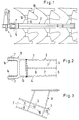
- Weitere Einzelheiten und Vorteile ergeben sich aus der nachfolgenden Beschreibung und der Zeichnung, in der ein Ausführungsbeispiel des Gegenstands der Erfindung näher veranschaulicht ist. In der Zeichnung zeigen:
- Fig. 1 eine schematische Seitenansicht eines Drehpfluges mit einem Pflugrahmen nach der Erfindung,
- Fig. 2 eine abgebrochene Seitenansicht des vorderen Pflugrahmenbereiches in Vergrößerung, und
- Fig. 3 eine Draufsicht auf einen Abschnitt eines Pflugrahmens im Bereich eines Auslegers für die Grindelbefestigung.
- Der in Fig. 1 veranschaulichte, lediglich beispielsweise als Drehpflug ausgebildete Pflug umfaßt im einzelnen ein Pflugvordergestell 1, mit dem ein Pflugrahmen 2 um eine in Arbeitsstellung des Pfluges etwa lotrechte Gelenkachse 1′schwenkbar verbunden ist.
- Der Pflugrahmen 2 hat eine rohrförmige Grundgestalt und besteht aus zwei U-förmigen Formteilen 3,4, die eine untereinander gleiche Ausbildung haben, sowie aus einem gabelförmigen Gelenkanschlußkopf 5. Die U-förmigen Formteile 3,4 weisen jeweils Schenkel 6 auf, die sich in Fahrtrichtung, d.h. vom rückwärtigen Ende zum vorderen Ende des Pflugrahmens 2 hin, stetig verbreitern und dabei in Arbeitsstellung des Pflugrahmens horizontal verlaufen, so daß der Pflugrahmen 2 ein Querschnittsprofil aufweist, dessen Höhe sich in Fahrtrichtung vergrößert.
- Die Mittelstege 7 der Formteile 3,4 haben bevorzugt eine über die Länge des Pflugrahmens 2 gleichbleibende Breite, so daß bei einheitlicher Wanddicke der Formteile 3,4 der Pflugrahmen 2 über seine Länge in der Breite unverändert bleibt.
- Die Formteile 3,4 sind bevorzugt aus formgebogenen bzw. abgekanteten Flachblechzuschnitten gebildet, die über die Länge des Pflugrahmens 2 einstückig sind.
- Die Formteile 3,4 sind an den freien Randkanten ihrer Schenkel 6 untereinander durch eine Schweißnaht 8 verbunden, die als gerade, durchgehende Naht sehr einfach zu erstellen ist. Vor dem Verschweißen der Formteile 3,4 können im Bereich der Ausleger 9 für die Befestigung von Grindeln 10 von Pflugkörpern 11 in den Formteilen 3,4 Querwände 12 eingeschweißt werden, die Ausbeulerscheinungen unter Belastung entgegenwirken.
- Der Gelenkanschlußkopf 5 am vorderen Rahmenende weist ein kastenförmiges rückwärtiges Anschlußteil 13 auf, dessen rückwärtiger Rand den vorderen Rändern der Formteile 3,4 fluchtend gegenüberliegt und mit diesen durch eine umlaufende V-Schweißnaht verbunden ist. Bei dieser Gestaltung schneidet die durch die Aufnahmebohrungen 14 des Gelenkanschlußkopfes 5 definierte Gelenkachse l′die Mittelachse 15 des Pflugrahmens 2.
Claims (8)
Priority Applications (1)
| Application Number | Priority Date | Filing Date | Title |
|---|---|---|---|
| AT88118891T ATE77530T1 (de) | 1987-11-18 | 1988-11-12 | Rohrfoermiger pflugrahmen. |
Applications Claiming Priority (2)
| Application Number | Priority Date | Filing Date | Title |
|---|---|---|---|
| DE8715283U DE8715283U1 (de) | 1987-11-18 | 1987-11-18 | Rohrförmiger Pflugrahmen |
| DE8715283U | 1987-11-18 |
Publications (3)
| Publication Number | Publication Date |
|---|---|
| EP0316824A2 true EP0316824A2 (de) | 1989-05-24 |
| EP0316824A3 EP0316824A3 (en) | 1990-08-08 |
| EP0316824B1 EP0316824B1 (de) | 1992-06-24 |
Family
ID=6814208
Family Applications (1)
| Application Number | Title | Priority Date | Filing Date |
|---|---|---|---|
| EP88118891A Expired - Lifetime EP0316824B1 (de) | 1987-11-18 | 1988-11-12 | Rohrförmiger Pflugrahmen |
Country Status (5)
| Country | Link |
|---|---|
| EP (1) | EP0316824B1 (de) |
| AT (1) | ATE77530T1 (de) |
| DE (2) | DE8715283U1 (de) |
| ES (1) | ES2034119T3 (de) |
| NO (1) | NO885138L (de) |
Family Cites Families (2)
| Publication number | Priority date | Publication date | Assignee | Title |
|---|---|---|---|---|
| GB1585521A (en) * | 1977-10-05 | 1981-03-04 | Dowdeswell C | Plough beam |
| GB8617490D0 (en) * | 1986-07-17 | 1986-08-28 | Dowdeswell C V R | Reversible point mounting |
-
1987
- 1987-11-18 DE DE8715283U patent/DE8715283U1/de not_active Expired
-
1988
- 1988-11-12 ES ES198888118891T patent/ES2034119T3/es not_active Expired - Lifetime
- 1988-11-12 DE DE8888118891T patent/DE3872353D1/de not_active Expired - Fee Related
- 1988-11-12 EP EP88118891A patent/EP0316824B1/de not_active Expired - Lifetime
- 1988-11-12 AT AT88118891T patent/ATE77530T1/de not_active IP Right Cessation
- 1988-11-17 NO NO88885138A patent/NO885138L/no unknown
Also Published As
| Publication number | Publication date |
|---|---|
| ES2034119T3 (es) | 1993-04-01 |
| EP0316824A3 (en) | 1990-08-08 |
| NO885138D0 (no) | 1988-11-17 |
| DE3872353D1 (de) | 1992-07-30 |
| DE8715283U1 (de) | 1988-01-21 |
| NO885138L (no) | 1989-05-19 |
| ATE77530T1 (de) | 1992-07-15 |
| EP0316824B1 (de) | 1992-06-24 |
Similar Documents
| Publication | Publication Date | Title |
|---|---|---|
| DE2521805A1 (de) | Ausleger | |
| DE3129098A1 (de) | Tragendes chassis fuer ein bewegliches arbeitsgeraet mit einem mittelteil und laengstraegern | |
| DE3510590C2 (de) | ||
| EP3456888B1 (de) | Baggerausleger und bagger | |
| AT389621B (de) | Balkenfoermiger ausleger, insbesondere als spruehrahmen fuer pflanzenschutzgeraete | |
| DE756237C (de) | Selbsttragender Wagenkasten | |
| EP0316824B1 (de) | Rohrförmiger Pflugrahmen | |
| DE60309091T2 (de) | Dreieckskonfiguration für einen Gitterträger | |
| EP3715557A1 (de) | Knickmast mit mastsegmenten und verfahren zur herstellung eines mastsegmentes | |
| DE3116365A1 (de) | Foerderkette | |
| DE689352C (de) | Metallstrasse | |
| DE2703539A1 (de) | Teleskopischer kranausleger | |
| DE767715C (de) | Rahmen, insbesondere fuer Kraftfahrzeuge | |
| DE2756643A1 (de) | Schaufel fuer einen schaufelbagger | |
| DE3632067A1 (de) | Ladebordplattform fuer kraftfahrzeuge | |
| DE69204672T2 (de) | Rahmenteil für ein fahrzeug. | |
| DE1122024B (de) | Kappe aus Kastenprofil | |
| DE833935C (de) | An einem Traegerprofil anzubringendes Schlossteil fuer durch Schloesser miteinander zu verbindende Ausbautraeger | |
| DE60212516T2 (de) | Gitterträger | |
| DE2253567A1 (de) | Fuehrung fuer einen hobel od. dgl | |
| DE2308296A1 (de) | Zahn fuer erdbewegungsmaschinen, beispielsweise exkavatoren | |
| DE420535C (de) | Haengebock aus gestanzten Blechen | |
| DE617073C (de) | Laschenverbindung mittels Schweissung | |
| DE1813247A1 (de) | Schneidglied fuer Saegeketten | |
| DE960715C (de) | Grubenausbauprofil |
Legal Events
| Date | Code | Title | Description |
|---|---|---|---|
| PUAI | Public reference made under article 153(3) epc to a published international application that has entered the european phase |
Free format text: ORIGINAL CODE: 0009012 |
|
| AK | Designated contracting states |
Kind code of ref document: A2 Designated state(s): AT CH DE ES FR GB LI NL SE |
|
| PUAL | Search report despatched |
Free format text: ORIGINAL CODE: 0009013 |
|
| AK | Designated contracting states |
Kind code of ref document: A3 Designated state(s): AT CH DE ES FR GB LI NL SE |
|
| 17P | Request for examination filed |
Effective date: 19900912 |
|
| 17Q | First examination report despatched |
Effective date: 19911122 |
|
| GRAA | (expected) grant |
Free format text: ORIGINAL CODE: 0009210 |
|
| AK | Designated contracting states |
Kind code of ref document: B1 Designated state(s): AT CH DE ES FR GB LI NL SE |
|
| REF | Corresponds to: |
Ref document number: 77530 Country of ref document: AT Date of ref document: 19920715 Kind code of ref document: T |
|
| REF | Corresponds to: |
Ref document number: 3872353 Country of ref document: DE Date of ref document: 19920730 |
|
| ET | Fr: translation filed | ||
| GBT | Gb: translation of ep patent filed (gb section 77(6)(a)/1977) | ||
| REG | Reference to a national code |
Ref country code: ES Ref legal event code: FG2A Ref document number: 2034119 Country of ref document: ES Kind code of ref document: T3 |
|
| PLBE | No opposition filed within time limit |
Free format text: ORIGINAL CODE: 0009261 |
|
| STAA | Information on the status of an ep patent application or granted ep patent |
Free format text: STATUS: NO OPPOSITION FILED WITHIN TIME LIMIT |
|
| 26N | No opposition filed | ||
| EAL | Se: european patent in force in sweden |
Ref document number: 88118891.6 |
|
| PGFP | Annual fee paid to national office [announced via postgrant information from national office to epo] |
Ref country code: CH Payment date: 19951117 Year of fee payment: 8 |
|
| PG25 | Lapsed in a contracting state [announced via postgrant information from national office to epo] |
Ref country code: LI Effective date: 19961130 Ref country code: CH Effective date: 19961130 |
|
| REG | Reference to a national code |
Ref country code: CH Ref legal event code: PL |
|
| PGFP | Annual fee paid to national office [announced via postgrant information from national office to epo] |
Ref country code: SE Payment date: 19980917 Year of fee payment: 11 |
|
| PGFP | Annual fee paid to national office [announced via postgrant information from national office to epo] |
Ref country code: DE Payment date: 19981002 Year of fee payment: 11 |
|
| PGFP | Annual fee paid to national office [announced via postgrant information from national office to epo] |
Ref country code: GB Payment date: 19981104 Year of fee payment: 11 |
|
| PGFP | Annual fee paid to national office [announced via postgrant information from national office to epo] |
Ref country code: AT Payment date: 19981119 Year of fee payment: 11 |
|
| PGFP | Annual fee paid to national office [announced via postgrant information from national office to epo] |
Ref country code: ES Payment date: 19981124 Year of fee payment: 11 |
|
| PGFP | Annual fee paid to national office [announced via postgrant information from national office to epo] |
Ref country code: NL Payment date: 19981130 Year of fee payment: 11 Ref country code: FR Payment date: 19981130 Year of fee payment: 11 |
|
| PG25 | Lapsed in a contracting state [announced via postgrant information from national office to epo] |
Ref country code: GB Free format text: LAPSE BECAUSE OF NON-PAYMENT OF DUE FEES Effective date: 19991112 Ref country code: AT Free format text: LAPSE BECAUSE OF NON-PAYMENT OF DUE FEES Effective date: 19991112 |
|
| PG25 | Lapsed in a contracting state [announced via postgrant information from national office to epo] |
Ref country code: SE Free format text: LAPSE BECAUSE OF NON-PAYMENT OF DUE FEES Effective date: 19991113 Ref country code: ES Free format text: LAPSE BECAUSE OF NON-PAYMENT OF DUE FEES Effective date: 19991113 |
|
| PG25 | Lapsed in a contracting state [announced via postgrant information from national office to epo] |
Ref country code: NL Free format text: LAPSE BECAUSE OF NON-PAYMENT OF DUE FEES Effective date: 20000601 |
|
| GBPC | Gb: european patent ceased through non-payment of renewal fee |
Effective date: 19991112 |
|
| EUG | Se: european patent has lapsed |
Ref document number: 88118891.6 |
|
| PG25 | Lapsed in a contracting state [announced via postgrant information from national office to epo] |
Ref country code: FR Free format text: LAPSE BECAUSE OF NON-PAYMENT OF DUE FEES Effective date: 20000731 |
|
| NLV4 | Nl: lapsed or anulled due to non-payment of the annual fee |
Effective date: 20000601 |
|
| PG25 | Lapsed in a contracting state [announced via postgrant information from national office to epo] |
Ref country code: DE Free format text: LAPSE BECAUSE OF NON-PAYMENT OF DUE FEES Effective date: 20000901 |
|
| REG | Reference to a national code |
Ref country code: FR Ref legal event code: ST |
|
| REG | Reference to a national code |
Ref country code: ES Ref legal event code: FD2A Effective date: 20001214 |