EP0316876B1 - Digitalsignalempfangsschaltung mit Baudabtastphasensteuerung durch eine Leistung von abgetasteten Signalen - Google Patents
Digitalsignalempfangsschaltung mit Baudabtastphasensteuerung durch eine Leistung von abgetasteten Signalen Download PDFInfo
- Publication number
- EP0316876B1 EP0316876B1 EP88119033A EP88119033A EP0316876B1 EP 0316876 B1 EP0316876 B1 EP 0316876B1 EP 88119033 A EP88119033 A EP 88119033A EP 88119033 A EP88119033 A EP 88119033A EP 0316876 B1 EP0316876 B1 EP 0316876B1
- Authority
- EP
- European Patent Office
- Prior art keywords
- signal
- sampling
- receiving circuit
- series
- calculating
- Prior art date
- Legal status (The legal status is an assumption and is not a legal conclusion. Google has not performed a legal analysis and makes no representation as to the accuracy of the status listed.)
- Expired - Lifetime
Links
Images


Classifications
-
- H—ELECTRICITY
- H04—ELECTRIC COMMUNICATION TECHNIQUE
- H04L—TRANSMISSION OF DIGITAL INFORMATION, e.g. TELEGRAPHIC COMMUNICATION
- H04L7/00—Arrangements for synchronising receiver with transmitter
- H04L7/0054—Detection of the synchronisation error by features other than the received signal transition
-
- H—ELECTRICITY
- H04—ELECTRIC COMMUNICATION TECHNIQUE
- H04L—TRANSMISSION OF DIGITAL INFORMATION, e.g. TELEGRAPHIC COMMUNICATION
- H04L7/00—Arrangements for synchronising receiver with transmitter
- H04L7/02—Speed or phase control by the received code signals, the signals containing no special synchronisation information
- H04L7/033—Speed or phase control by the received code signals, the signals containing no special synchronisation information using the transitions of the received signal to control the phase of the synchronising-signal-generating means, e.g. using a phase-locked loop
- H04L7/0334—Processing of samples having at least three levels, e.g. soft decisions
Definitions
- the present invention relates to a receiving circuit for use in a transmission system of a digital signal with a transmission baud rate, and in particular, to such a receiving circuit of a baud rate sampling type wherein the digital signal is sampled as a received signal at a sampling rate equal to the transmission baud rate.
- Such a receiver comprises a baud rate sampler for sampling the received signal at a sampling rate equal to the transmission baud rate to produce a series of sampled signals and a decision circuit for deciding the series of the sampled signals.
- the sampling manner using the sampling rate equal to the transmission baud rate is called a baud rate sampling.
- Another sampling manner is also possible wherein the received signal is sampled at a sampling rate twice or more of the transmission baud rate.
- the former enables to reduce a signal processing time and a filter tap number in, for example, a line equalizer and is therefore superior to the latter.
- a synchroniser for analogue modulation transmitted data operates on digital information transmitted by analogue modulation and comprises a receiver clock supplying a first reception clock signal at a frequency which is a multiple at the information transmission frequency. This signal is applied to a dephasing control.
- the analogue signal is rectified and a sampler takes the rectified signal with the aid of the clock signal, N groups of M successive samples being stored.
- An adder sums the amplitudes of N samples at the same value M a variable integer from 1 to M within each group of M samples, and the dephaser is controlled to dephase the clock as a function of the results from the adder for various values of M.
- a difficulty which the baud rate sampling suffers from is control of the sampling phase, that is, timing control for sampling.
- Müller et al proposed to utilize an impulse response of the series of received signals and a decided result at the decision circuit in their paper "Timing Recovery in Digital Synchronous Data Receiver", IEEE Transaction on communication, VOL. COM-24, NO. 5, MAY 1976 (Reference 1).
- this technique has a problem that correct operation is not expected when the decided result includes many errors, for example, at a training phase of the receiver operation.
- the present invention can be applicable to a receiving circuit for use in a transmission system of a digital signal at a transmission baud rate, the receiving circuit comprising a baud rate sampling circuit for sampling the digital signal as a received signal by a sampling signal of a sampling rate equal to the transmission baud rate to produce a series of sampled signals.
- the receiving circuit comprises calculating means coupled with the baud rate sampling circuit for calculating a linear summation of predetermined elements of an autocorrelation function of the series of sampled signals as a power of the series of sampled signals, and sampling control means responsive to the power for controlling a sampling phase of the sampling signal so that the power of the series of sampled signals is maximized.
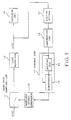
- the receiving circuit shown therein receives a data signal r(t) transmitted through a transmission line (not shown) at a transmission baud rate.
- the receiving circuit comprises a baud rate sampling circuit 11 for sampling the received data signal by a sampling signal to produce a series of sampled signal, a sampling signal generator 12 for generating the sampling signal with a sampling rate equal to the transmission baud rate, a line equalizer 13 for equalizing the series of sampled signals, and a decision circuit 14 for deciding the series of sampled signals after equalized.
- baud rate sampling circuit 11, sampling signal generating circuit 12, line equalizer 13, and decision circuit 14 are known in the prior art. Therefore, description thereto is omitted herein for the purpose of simplification of the description.
- the receiving circuit further comprises a digital filter 15, a calculating circuit 16, and a control circuit 17 for controlling a phase of the sampling signal, that is, a sampling phase at the baud rate sampling circuit 11.
- the series of sampled and equalized signals x(t) at an output of the line equalizer 13 is well known in the prior art to be given by: where T represents an inverse of the baud rate or the sampling rate and is corresponding to a sampling interval, n being an integer.
- C(iT) E[x(t) ⁇ x(t - iT)] (2)
- E[X] represents an expectation of X, i being an integer.
- Equation (1) Equation (1)
- Equation (3) Providing that x(kt + ⁇ ) and h(kT + ⁇ ) are represented by x k, ⁇ and h k, ⁇ , Equation (3) is rewritten into:
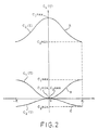
- a ratio (C1max/C1min and C2max/C2min) of the maximum and the minimum of each of C1( ⁇ ) and C2( ⁇ ) is larger than that (C0max/C0min) of C0( ⁇ ). Therefore, it will be appreciated that use of summation of two or more elements of the autocorrelation function C i ( ⁇ ) prefers to use of C0( ⁇ ) alone for detecting the optimum sampling phase.
- a linear summation P of the autocorrelation function C i ( ⁇ ) is given by the following equation (6): where gi is a weight coefficient. Optimization of gi depends on transmitted pulse duty and some other transmission parameter.
- the digital filter 15 and the calculating circuit 16 are for obtaining P.
- the digital filter 15 has a filtering characteristic of (1 - Z ⁇ 1)
- the digital filter 15 is placed in the portion of the line equalizer.
- control circuit 17 previously controls the sampling signal generating circuit 12 to thereby change the sampling phase in various phases.
- the control circuit 17 detects the maximum one of powers calculated by the calculating circuit 16 at the various phases and controls the sampling phase to hold the maximum power.
- the optimum sampling phase can be detected without use of C0( ⁇ ) but with use of other elements, for example, C1( ⁇ ) and C2( ⁇ ) of the autocorrelation function. In that case, the digital filter 15 is not necessary.
- the receiving circuit is similar to that of Fig. 1 but is different in that the digital filter is not used.
- the calculating circuit 16 calculates a linear summation of predetermined elements of the autocorrelation function C i ( ⁇ ).
- the first portion 20 comprises two delay circuits 23 and 24 each for delaying an input signal by a time period of T and two multipliers 26 and 27.
- the delay circuit 23 produces x k-1, ⁇ which are supplied to the other delay circuit 24 and the multiplier 26.
- the second portion 21 comprises a summing circuit 28 and the third portion 22 comprises an adder 29 and a delay circuit 30 connected in series with each other.
- An output of the summing circuit 28 is added to an output from the delay circuit 30 to produce an added result which is delayed by the delay circuit 30 to produce a delayed signal as the output from the delay circuit 30.
- the delayed signal is integration of the output from the summing circuit 28.
- the delay circuit 30 is reset after the predetermined time period or when integration is performed by M times.
- the calculating circuit 16 can be constructed for calculating a linear summation of desired elements of the autocorrelation function C i ( ⁇ ) by use of known delay circuits, multipliers and summing circuits in the manner analogous to Fig. 4.
- the calculated result M ⁇ P 1,2 is supplied to the control circuit 17.
- the control circuit 17 controls the sampling phase of the sampling signal in the manner as described above in connection with Fig. 1.
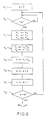
- the calculating circuit 16 can also be realized by a combination of a processor 31 for executing calculation of P, a read only memory (ROM) 32 for memorizing a program for the calculation and the weight coefficients gi, and a random access memory (RAM) 33 for storing the series of sampled and equalized signals x(t).
- a processor 31 for executing calculation of P
- ROM read only memory
- RAM random access memory
- x in is supplied as a first one
- the processor 31 stores x in as x1 in RAM 33 as shown in step S3.
- the processor 31 stores the second one of x in as x1 in RAM 33 and rewrites the previous one of x1 into x2 at step S2.
- the processor 31 rewrites x1, x2, and x3 into a current one of x in , a previous one of x1, and a previous one of x2, respectively, each supply of x in .
- calculating circuit of Fig. 5 can also be formed to calculate a linear summation of desired elements of the autocorrelation function C i ( ⁇ ) by modifying the program.
Landscapes
- Engineering & Computer Science (AREA)
- Computer Networks & Wireless Communication (AREA)
- Signal Processing (AREA)
- Synchronisation In Digital Transmission Systems (AREA)
- Digital Transmission Methods That Use Modulated Carrier Waves (AREA)
- Cable Transmission Systems, Equalization Of Radio And Reduction Of Echo (AREA)
- Peptides Or Proteins (AREA)
Claims (7)
- Empfangsschaltung zur Verwendung in einem Übertragungssystem eines Digitalsignals mit einer Übertragungs-Baudrate, wobei die Empfangsschaltung eine Baudrate-Abtastschaltung (11) zum Abtasten des Digitalsignals als ein empfangenes Signal durch ein Abtastsignal (12) mit einer Abtastrate, die gleich der Übertragungs-Baudrate ist, umfaßt, um eine Reihe abgetasteter Signale zu erzeugen, die gekennzeichnet ist durch:
eine mit der Baudrate-Abtastschaltung (11) verbundene Berechnungseinrichtung (16) zur Berechnung einer linearen Gesamtsumme von bestimmten Elementen einer Autokorrelationsfunktion der Reihe abgetasteter Signale als eine Leistung der Reihe abgetasteter Signale; und
eine auf die Leistung ansprechende Abtaststeuereinrichtung (17) zur Steuerung der Abtastphase des Abtastsignals, so daß die Leistung maximiert wird. - Empfangsschaltung nach Anspruch 1, die ferner einen Digitalfilter (15) umfaßt, um die Reihe abgetasteter Signale zu filtern und sie der Berechnungseinrichtung (16) zu übergeben.
- Empfangsschaltung nach Anspruch 2, wobei der Digitalfilter (15) eine Filtriercharakteristik (1 - Z⁻¹) besitzt.
- Empfangsschaltung nach Anspruch 1, wobei die Berechnungseinrichtung (16) eine erste Einrichtung (20) zur Berechnung der bestimmten Elemente der Autokorrelationsfunktion der Reihe abgetasteter Signale, um berechnete Datensignale zu erzeugen, eine zweite Einrichtung (21) zur Summation des berechneten Datensignals, um ein summiertes Datensignal zu erzeugen, und eine dritte Einrichtung (22) zur Integration des summierten Datensignals über eine bestimmte Zeitdauer umfaßt, um ein integriertes Signal als eine lineare Gesamtsumme zu erzeugen.
- Empfangsschaltung nach Anspruch 4, wobei die erste Einrichtung (20) eine bestimmte Anzahl an Verzögerungseinrichtungen (23, 24), von denen jede eine Verzögerungszeit besitzt, die gleich einer der Abtastrate entsprechenden Abtastperiode ist, und die in einer Kaskade zur Verzögerung der Reihe abgetasteter Signale verbunden ist, wobei jede Verzögerungseinrichtung (23, 24) verzögerte Signale übergibt, und mehrere jeweils mit den Verzögerungseinrichtungen (23, 24) verbundene Multipliziereinrichtungen (26, 27) zur Multiplikation der verzögerten Signale mit der Reihe abgetasteter Signale umfaßt, um jeweils berechnete Daten-signale zu erzeugen.
- Empfangsschaltung nach Anspruch 4, wobei die dritte Einrichtung (22) eine Addiereinrichtung (29) zur Addition des summierten Datensignals und eines Additionssignals, um ein addiertes Signal zu erzeugen, und eine Verzögerungseinrichtung (30) zur Verzögerung des addierten Signals umfaßt, um das integrierte Signal zu erzeugen, wobei das integrierte Signal der Addiereinrichtung (29) als das Additionssignal zugeführt wird.
- Empfangsschaltung nach Anspruch 1, wobei die Berechnungseinrichtung (16) einen Festspeicher (ROM) (32) zur Speicherung eines Programms, das die lineare Gesamtsumme berechnet, einen Random-Speicher (RAM) (33) zur Speicherung der Reihe abgetasteter Signale und eine Verarbeitungseinrichtung (31) zur Ausführung des Berechnungsprogramms umfaßt, um die lineare Gesamtsumme als die Leistung unter Mitwirkung des Festspeichers (32) und des Random-Speichers (33) zu erzeugen.
Applications Claiming Priority (2)
| Application Number | Priority Date | Filing Date | Title |
|---|---|---|---|
| JP288940/87 | 1987-11-16 | ||
| JP28894087 | 1987-11-16 |
Publications (3)
| Publication Number | Publication Date |
|---|---|
| EP0316876A2 EP0316876A2 (de) | 1989-05-24 |
| EP0316876A3 EP0316876A3 (de) | 1991-05-08 |
| EP0316876B1 true EP0316876B1 (de) | 1994-01-26 |
Family
ID=17736778
Family Applications (1)
| Application Number | Title | Priority Date | Filing Date |
|---|---|---|---|
| EP88119033A Expired - Lifetime EP0316876B1 (de) | 1987-11-16 | 1988-11-15 | Digitalsignalempfangsschaltung mit Baudabtastphasensteuerung durch eine Leistung von abgetasteten Signalen |
Country Status (5)
| Country | Link |
|---|---|
| US (1) | US5048060A (de) |
| EP (1) | EP0316876B1 (de) |
| AU (1) | AU610658B2 (de) |
| CA (1) | CA1305768C (de) |
| DE (1) | DE3887459T2 (de) |
Families Citing this family (54)
| Publication number | Priority date | Publication date | Assignee | Title |
|---|---|---|---|---|
| GB9019491D0 (en) * | 1990-09-06 | 1990-10-24 | Ncr Co | Clock recovery for a wireless local area network station |
| US5263026A (en) * | 1991-06-27 | 1993-11-16 | Hughes Aircraft Company | Maximum likelihood sequence estimation based equalization within a mobile digital cellular receiver |
| US5214675A (en) * | 1991-07-02 | 1993-05-25 | Motorola, Inc. | System and method for calculating channel gain and noise variance of a communication channel |
| US5309483A (en) * | 1991-09-16 | 1994-05-03 | Motorola, Inc. | Data recovery device |
| FR2685486B1 (fr) * | 1991-12-19 | 1994-07-29 | Inst Francais Du Petrole | Methode et dispositif pour mesurer les niveaux d'amplitude successifs de signaux recus sur une voie de transmission. |
| US5353312A (en) * | 1991-12-27 | 1994-10-04 | At&T Bell Laboratories | Equalizer-based timing recovery |
| US5318533A (en) * | 1992-02-21 | 1994-06-07 | Scimed Life Systems, Inc. | Balloon catheter inflation device including apparatus for monitoring and wireless transmission of inflation data, and system |
| US5247544A (en) * | 1992-03-26 | 1993-09-21 | Motorola, Inc. | Phase adjustment method and apparatus for use in a clock recovery circuit |
| US5742189A (en) * | 1994-09-16 | 1998-04-21 | Kabushiki Kaisha Toshiba | Frequency conversion circuit and radio communication apparatus with the same |
| US5581585A (en) * | 1994-10-21 | 1996-12-03 | Level One Communications, Inc. | Phase-locked loop timing recovery circuit |
| US5499273A (en) * | 1995-05-11 | 1996-03-12 | Motorola, Inc. | Method and apparatus for symbol clock recovery from signal having wide frequency possibilities |
| US5802118A (en) * | 1996-07-29 | 1998-09-01 | Cirrus Logic, Inc. | Sub-sampled discrete time read channel for computer storage systems |
| DE19724027C2 (de) * | 1997-06-06 | 1999-09-30 | Siemens Ag | Verfahren und Anordnung zum Empfang von Daten |
| US6266172B1 (en) * | 1997-11-06 | 2001-07-24 | Agere Systems Optoelectronics Guardian Corp. | Signal bit rate and performance measurement for optical channel signals |
| EP1116356B1 (de) | 1998-09-23 | 2008-03-12 | Infineon Technologies AG | Vorrichtung und verfahren zur regelung des abtasttaktes in einem datenübertragungssystem |
| KR100525548B1 (ko) * | 2000-12-29 | 2005-10-31 | 엘지전자 주식회사 | 범용 비동기화 송수신기의 전송률 검출회로 |
| EP1453238A1 (de) * | 2003-02-25 | 2004-09-01 | CoreOptics, Inc., c/o The Corporation Trust Center | Verfahren und Schaltung zur Einstellung der Abtastphase in einem überabgetasteten Empfänger |
| US20040223567A1 (en) * | 2003-05-09 | 2004-11-11 | Ming-Kang Liu | Clock recovery system |
| US20040223568A1 (en) * | 2003-05-09 | 2004-11-11 | Ming-Kang Liu | Phase sampling determination system |
| WO2005122460A1 (en) * | 2004-06-04 | 2005-12-22 | Opelcomm, Inc. | Clock recovery system and phase sampling determination system |
| US7775966B2 (en) | 2005-02-24 | 2010-08-17 | Ethicon Endo-Surgery, Inc. | Non-invasive pressure measurement in a fluid adjustable restrictive device |
| US7658196B2 (en) | 2005-02-24 | 2010-02-09 | Ethicon Endo-Surgery, Inc. | System and method for determining implanted device orientation |
| US7927270B2 (en) | 2005-02-24 | 2011-04-19 | Ethicon Endo-Surgery, Inc. | External mechanical pressure sensor for gastric band pressure measurements |
| US7775215B2 (en) | 2005-02-24 | 2010-08-17 | Ethicon Endo-Surgery, Inc. | System and method for determining implanted device positioning and obtaining pressure data |
| US7699770B2 (en) | 2005-02-24 | 2010-04-20 | Ethicon Endo-Surgery, Inc. | Device for non-invasive measurement of fluid pressure in an adjustable restriction device |
| US8066629B2 (en) | 2005-02-24 | 2011-11-29 | Ethicon Endo-Surgery, Inc. | Apparatus for adjustment and sensing of gastric band pressure |
| US8016744B2 (en) | 2005-02-24 | 2011-09-13 | Ethicon Endo-Surgery, Inc. | External pressure-based gastric band adjustment system and method |
| US8152710B2 (en) | 2006-04-06 | 2012-04-10 | Ethicon Endo-Surgery, Inc. | Physiological parameter analysis for an implantable restriction device and a data logger |
| US8870742B2 (en) | 2006-04-06 | 2014-10-28 | Ethicon Endo-Surgery, Inc. | GUI for an implantable restriction device and a data logger |
| US8187163B2 (en) | 2007-12-10 | 2012-05-29 | Ethicon Endo-Surgery, Inc. | Methods for implanting a gastric restriction device |
| US8100870B2 (en) | 2007-12-14 | 2012-01-24 | Ethicon Endo-Surgery, Inc. | Adjustable height gastric restriction devices and methods |
| US8142452B2 (en) | 2007-12-27 | 2012-03-27 | Ethicon Endo-Surgery, Inc. | Controlling pressure in adjustable restriction devices |
| US8377079B2 (en) | 2007-12-27 | 2013-02-19 | Ethicon Endo-Surgery, Inc. | Constant force mechanisms for regulating restriction devices |
| US8192350B2 (en) | 2008-01-28 | 2012-06-05 | Ethicon Endo-Surgery, Inc. | Methods and devices for measuring impedance in a gastric restriction system |
| US8337389B2 (en) | 2008-01-28 | 2012-12-25 | Ethicon Endo-Surgery, Inc. | Methods and devices for diagnosing performance of a gastric restriction system |
| US8591395B2 (en) | 2008-01-28 | 2013-11-26 | Ethicon Endo-Surgery, Inc. | Gastric restriction device data handling devices and methods |
| US8221439B2 (en) | 2008-02-07 | 2012-07-17 | Ethicon Endo-Surgery, Inc. | Powering implantable restriction systems using kinetic motion |
| US7844342B2 (en) | 2008-02-07 | 2010-11-30 | Ethicon Endo-Surgery, Inc. | Powering implantable restriction systems using light |
| US8114345B2 (en) | 2008-02-08 | 2012-02-14 | Ethicon Endo-Surgery, Inc. | System and method of sterilizing an implantable medical device |
| US8057492B2 (en) | 2008-02-12 | 2011-11-15 | Ethicon Endo-Surgery, Inc. | Automatically adjusting band system with MEMS pump |
| US8591532B2 (en) | 2008-02-12 | 2013-11-26 | Ethicon Endo-Sugery, Inc. | Automatically adjusting band system |
| US8034065B2 (en) | 2008-02-26 | 2011-10-11 | Ethicon Endo-Surgery, Inc. | Controlling pressure in adjustable restriction devices |
| US8233995B2 (en) | 2008-03-06 | 2012-07-31 | Ethicon Endo-Surgery, Inc. | System and method of aligning an implantable antenna |
| US8187162B2 (en) | 2008-03-06 | 2012-05-29 | Ethicon Endo-Surgery, Inc. | Reorientation port |
| WO2010019169A1 (en) * | 2008-08-15 | 2010-02-18 | Lsi Corporation | Rom list-decoding of near codewords |
| EP2307960B1 (de) | 2009-04-21 | 2018-01-10 | Avago Technologies General IP (Singapore) Pte. Ltd. | Error-floor-senkung von codes mit schreibverifikation |
| EP2252003A1 (de) | 2009-05-12 | 2010-11-17 | CoreOptics Inc. | Phasenbestimmungsverfahren und Phasendetektor |
| US9537578B2 (en) * | 2009-12-15 | 2017-01-03 | Multiphy Ltd. | Method and system for coherent equalization of chromatic dispersion of optical signals in a fiber |
| US8464142B2 (en) | 2010-04-23 | 2013-06-11 | Lsi Corporation | Error-correction decoder employing extrinsic message averaging |
| US8499226B2 (en) | 2010-06-29 | 2013-07-30 | Lsi Corporation | Multi-mode layered decoding |
| US8458555B2 (en) | 2010-06-30 | 2013-06-04 | Lsi Corporation | Breaking trapping sets using targeted bit adjustment |
| US8504900B2 (en) * | 2010-07-02 | 2013-08-06 | Lsi Corporation | On-line discovery and filtering of trapping sets |
| US8768990B2 (en) | 2011-11-11 | 2014-07-01 | Lsi Corporation | Reconfigurable cyclic shifter arrangement |
| RU2012146685A (ru) | 2012-11-01 | 2014-05-10 | ЭлЭсАй Корпорейшн | База данных наборов-ловушек для декодера на основе разреженного контроля четности |
Family Cites Families (7)
| Publication number | Priority date | Publication date | Assignee | Title |
|---|---|---|---|---|
| FR2493646A1 (fr) * | 1980-10-31 | 1982-05-07 | Thomson Csf | Dispositif de synchronisation de donnees numeriques |
| FR2534426A1 (fr) * | 1982-10-11 | 1984-04-13 | Trt Telecom Radio Electr | Egaliseur auto-adaptatif pour signal de donnees en bande de base |
| DE3335417A1 (de) * | 1983-09-29 | 1985-04-18 | Siemens AG, 1000 Berlin und 8000 München | Empfangseinrichtung fuer eine bitserielle, asynchrone uebertragungsstrecke fuer hohe datenraten |
| US4815103A (en) * | 1987-10-29 | 1989-03-21 | American Telephone And Telegraph Company | Equalizer-based timing recovery |
| GB8800739D0 (en) * | 1988-01-13 | 1988-02-10 | Ncr Co | Multipoint modem system having fast synchronization |
| NL8800490A (nl) * | 1988-02-26 | 1989-09-18 | At & T & Philips Telecomm | Ontvanger van een stelsel voor het met gegeven baudsnelheid overdragen van datasymbolen. |
| US4856030A (en) * | 1988-07-20 | 1989-08-08 | Itt Defense Communications | Apparatus and methods of locking a receiving modem to a transmitting modem employing a burst signal |
-
1988
- 1988-11-15 EP EP88119033A patent/EP0316876B1/de not_active Expired - Lifetime
- 1988-11-15 CA CA000583093A patent/CA1305768C/en not_active Expired
- 1988-11-15 DE DE88119033T patent/DE3887459T2/de not_active Expired - Fee Related
- 1988-11-16 US US07/271,979 patent/US5048060A/en not_active Expired - Fee Related
- 1988-11-16 AU AU25612/88A patent/AU610658B2/en not_active Ceased
Also Published As
| Publication number | Publication date |
|---|---|
| AU2561288A (en) | 1989-05-18 |
| EP0316876A3 (de) | 1991-05-08 |
| EP0316876A2 (de) | 1989-05-24 |
| DE3887459T2 (de) | 1994-05-11 |
| DE3887459D1 (de) | 1994-03-10 |
| US5048060A (en) | 1991-09-10 |
| AU610658B2 (en) | 1991-05-23 |
| CA1305768C (en) | 1992-07-28 |
Similar Documents
| Publication | Publication Date | Title |
|---|---|---|
| EP0316876A2 (de) | Digitalsignalempfangsschaltung mit Baudabtastphasensteuerung durch eine Leistung von abgetasteten Signalen | |
| AU662087B2 (en) | A method and an arrangement of estimating transmitted symbols at a receiver in digital signal transmission | |
| US4789994A (en) | Adaptive equalizer using precursor error signal for convergence control | |
| US5285482A (en) | Timing recovery device for receiver installation using adaptive equalization and oversampling associated with differentially coherent demodulation | |
| EP0426026B1 (de) | Entzerrer | |
| EP0300449B1 (de) | Digitaler automatischer Leitungsentzerrer mit Mitteln zur Regelung der Anzapfungsverstärkung in Abhängigkeit der mittleren Filterausgangsleistung | |
| US5790598A (en) | Block decision feedback equalizer | |
| EP0023056B1 (de) | Vorrichtung mit einem nichtrekursiven Filter | |
| US4328585A (en) | Fast adapting fading channel equalizer | |
| EP0052362B1 (de) | System für die schnelle Voreinstellung von Transversalentzerrern | |
| US4766589A (en) | Data transmission system | |
| US5175747A (en) | Equalizer | |
| US5870438A (en) | Fast resynchronization system for high-speed data transmission | |
| US5369668A (en) | Fast response matched filter receiver with decision feedback equalizer | |
| CN1070666C (zh) | 一种时钟恢复电路及方法 | |
| EP0228771A2 (de) | Datenübertragungssystem | |
| US5272727A (en) | Adaptive maximum likelihood sequence estimator using channel estimators of respective order of impulse response | |
| JPH05183456A (ja) | 制御信号発生装置 | |
| EP0567211A2 (de) | Adaptiver Empfänger für Mehrwegkanäle mit Fading | |
| US4146840A (en) | Technique for obtaining symbol timing for equalizer weights | |
| EP0216183A2 (de) | Entscheidungsrückgekoppelter Entzerrer mit Musterdetektor | |
| EP0781481A1 (de) | Anordnung zur blindentzerrung | |
| US4225832A (en) | Self-adapting equalizer | |
| EP0413875B1 (de) | Taktsteuerung für Modemempfänger | |
| US4672637A (en) | Adaptive bit synchronizer |
Legal Events
| Date | Code | Title | Description |
|---|---|---|---|
| PUAI | Public reference made under article 153(3) epc to a published international application that has entered the european phase |
Free format text: ORIGINAL CODE: 0009012 |
|
| 17P | Request for examination filed |
Effective date: 19881115 |
|
| AK | Designated contracting states |
Kind code of ref document: A2 Designated state(s): DE FR GB |
|
| PUAL | Search report despatched |
Free format text: ORIGINAL CODE: 0009013 |
|
| AK | Designated contracting states |
Kind code of ref document: A3 Designated state(s): DE FR GB |
|
| 17Q | First examination report despatched |
Effective date: 19920904 |
|
| GRAA | (expected) grant |
Free format text: ORIGINAL CODE: 0009210 |
|
| AK | Designated contracting states |
Kind code of ref document: B1 Designated state(s): DE FR GB |
|
| REF | Corresponds to: |
Ref document number: 3887459 Country of ref document: DE Date of ref document: 19940310 |
|
| ET | Fr: translation filed | ||
| PG25 | Lapsed in a contracting state [announced via postgrant information from national office to epo] |
Ref country code: GB Effective date: 19941115 |
|
| PLBE | No opposition filed within time limit |
Free format text: ORIGINAL CODE: 0009261 |
|
| STAA | Information on the status of an ep patent application or granted ep patent |
Free format text: STATUS: NO OPPOSITION FILED WITHIN TIME LIMIT |
|
| 26N | No opposition filed | ||
| GBPC | Gb: european patent ceased through non-payment of renewal fee |
Effective date: 19941115 |
|
| PGFP | Annual fee paid to national office [announced via postgrant information from national office to epo] |
Ref country code: FR Payment date: 20021108 Year of fee payment: 15 |
|
| PGFP | Annual fee paid to national office [announced via postgrant information from national office to epo] |
Ref country code: DE Payment date: 20021121 Year of fee payment: 15 |
|
| PG25 | Lapsed in a contracting state [announced via postgrant information from national office to epo] |
Ref country code: DE Free format text: LAPSE BECAUSE OF NON-PAYMENT OF DUE FEES Effective date: 20040602 |
|
| PG25 | Lapsed in a contracting state [announced via postgrant information from national office to epo] |
Ref country code: FR Free format text: LAPSE BECAUSE OF NON-PAYMENT OF DUE FEES Effective date: 20040730 |
|
| REG | Reference to a national code |
Ref country code: FR Ref legal event code: ST |