EP0316888A1 - Dispositif de mesure de distance et de vitesse pour des véhicules guidés sur une voie - Google Patents
Dispositif de mesure de distance et de vitesse pour des véhicules guidés sur une voie Download PDFInfo
- Publication number
- EP0316888A1 EP0316888A1 EP88119054A EP88119054A EP0316888A1 EP 0316888 A1 EP0316888 A1 EP 0316888A1 EP 88119054 A EP88119054 A EP 88119054A EP 88119054 A EP88119054 A EP 88119054A EP 0316888 A1 EP0316888 A1 EP 0316888A1
- Authority
- EP
- European Patent Office
- Prior art keywords
- wheel
- circuit
- acceleration
- speed
- inertial
- Prior art date
- Legal status (The legal status is an assumption and is not a legal conclusion. Google has not performed a legal analysis and makes no representation as to the accuracy of the status listed.)
- Granted
Links
- 230000001133 acceleration Effects 0.000 claims abstract description 37
- 238000005259 measurement Methods 0.000 claims abstract description 23
- 238000001514 detection method Methods 0.000 claims abstract description 12
- 238000012545 processing Methods 0.000 claims abstract description 3
- 238000011156 evaluation Methods 0.000 claims description 23
- 238000006073 displacement reaction Methods 0.000 claims description 16
- 238000012937 correction Methods 0.000 claims description 15
- 238000011144 upstream manufacturing Methods 0.000 claims description 2
- 239000000872 buffer Substances 0.000 claims 2
- 238000004590 computer program Methods 0.000 claims 1
- 230000001419 dependent effect Effects 0.000 abstract description 12
- 230000003287 optical effect Effects 0.000 abstract description 3
- 241001609370 Puschkinia scilloides Species 0.000 abstract description 2
- 230000010354 integration Effects 0.000 abstract description 2
- 238000000034 method Methods 0.000 abstract description 2
- 230000001105 regulatory effect Effects 0.000 abstract 1
- 238000009987 spinning Methods 0.000 abstract 1
- 239000013589 supplement Substances 0.000 abstract 1
- 238000007664 blowing Methods 0.000 description 1
- 238000011109 contamination Methods 0.000 description 1
- 238000012544 monitoring process Methods 0.000 description 1
- 230000035945 sensitivity Effects 0.000 description 1
- 239000000758 substrate Substances 0.000 description 1
Images
Classifications
-
- G—PHYSICS
- G01—MEASURING; TESTING
- G01C—MEASURING DISTANCES, LEVELS OR BEARINGS; SURVEYING; NAVIGATION; GYROSCOPIC INSTRUMENTS; PHOTOGRAMMETRY OR VIDEOGRAMMETRY
- G01C22/00—Measuring distance traversed on the ground by vehicles, persons, animals or other moving solid bodies, e.g. using odometers, using pedometers
- G01C22/02—Measuring distance traversed on the ground by vehicles, persons, animals or other moving solid bodies, e.g. using odometers, using pedometers by conversion into electric waveforms and subsequent integration, e.g. using tachometer generator
Definitions
- the invention relates to a device for distance and speed measurement according to the preamble of patent claim 1.
- Such a device is known from DE-PS 28 13 078. It works satisfactorily as long as slip occurs only temporarily, when accelerating or braking, as is the case with the rail vehicles in use today.
- a known, wheel-independent measuring device e.g. a Doppler radar device or a device working with the aid of an optical correlation method
- disadvantages and inadequacies of the wheel-independent measuring device are compensated by the accelerometer and the wheel-dependent measuring system.
- disadvantages include the uncertainty in the detection of the direction of travel, the failure of the measurement on certain substrates (e.g. checker plates) and the sensitivity to external influences (e.g. pretending movement in snow drifts).
- optical position measuring systems in addition to the disadvantage mentioned last, there is above all the risk of failure due to contamination or icing of the optics.
- Embodiments of the device according to the invention are described in the subclaims:
- An embodiment described in claim 2 contains simple, discrete logic circuit arrangements for correcting the inertial acceleration in the two evaluation channels.
- Claim 3 specifies a possibility to protect the value of the slope acceleration from adulteration by slippage.
- Claim 4 relates to a possibility for automatic calibration of the wheel-dependent measuring system with the help of the wheel-independent measuring system. Regular checks of the wheel diameter and corresponding readjustment of the wheel pulse generator can thus be omitted.
- the subject matter of claim 5 enables a safe direction of travel specification for the second evaluation channel.
- Claim 6 finally, provides for the replacement of the discrete circuit parts by a computer which carries out the individual circuit functions according to a program designed according to the function of the device.
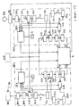
- a wheel-dependent displacement pulse generator RA an inertial accelerometer BM and a wheel-independent displacement measuring device WG are shown, which are located on the same vehicle.
- the output signals of the wheel-dependent displacement pulse generator RA and of the wheel-independent displacement measuring device WG are each fed to an evaluation channel AK1, AK2, those of the wheel-dependent transmitter being passed beforehand via a wheel diameter correction circuit RD, which changes the sequence of displacement pulses obtained from the wheel rotation in such a way that that measurement errors are compensated for by wear-related changes in the wheel diameter.
- the structure of the two evaluation channels corresponds to each other. In Both channels are obtained from an acceleration value a measured by the inertial acceleration sensor BM by two integration in series-connected integrating circuits JS1, JS2; JS3, JS4 obtained a value V K 1, V K 2 for the speed and a value S K 1, S K 2 for the distance covered by the vehicle.
- the acceleration value a is divided into two subtracting circuits SU2, SU3 ,. SU6, SU7 subjected to corrections. In doing so, it is first freed from falsification by the slope inclination, the so-called slope acceleration C1, C2, and then subjected to a drift correction.
- the slope acceleration C1 is obtained as the difference between the acceleration a measured by the inertial accelerometer and the acceleration b1 calculated from the pulse train of the wheel-dependent displacement pulse generator in a subtraction circuit SU1.
- the acceleration a measured by the accelerometer is fed directly to the subtracting circuit, the output signal of the wheel-dependent displacement pulse generator RA, after correction in the wheel diameter correction circuit RD, is previously fed to two differentiating circuits DF1, DF2 connected in series, of which it converts the first into a speed signal where the second wins the acceleration signal.
- the value of the slope acceleration C1 present at the output of the subtraction circuit SU1 is fed to the subtraction circuit SU2 via a limiter circuit BG1, a switch S1 and a low-pass filter TP1, where it is subtracted from the acceleration value a supplied by the inertial accelerometer.
- the simply corrected acceleration b K 1 remaining after the subtraction is then subjected to the drift correction in the subtracting circuit SU3 and finally fed to the integrating circuit JS1.
- the drift correction is carried out by subtracting a value d1, which is obtained in a further subtracting circuit SU4 and is proportional to the difference between corrected speed V K 1 and the speed obtained by the wheel pulse generator, from the simply corrected acceleration b K 1.
- the value d1 becomes from Stubtrating circuit SU4 is fed to the subtracting circuit SU3 via a further limiter circuit BG2, a further switch S2 and an amplifier VS1.
- the switch S2 which, like the switch S1, is controlled by a slip detection circuit SE1, the drift correction can be switched off when slip is detected.
- the switch S1 simultaneously disconnects the signal C1 which reproduces the slope acceleration from the input of the low pass TP1. At the output of the low pass, the signal that was last output then continues to appear for a certain time. If the cut-off frequency of the low-pass filter is selected to be very low, the low-pass filter acts like a memory from which slip occurring in phases, during which no useful value for the acceleration of the slope can be obtained from the number of wheel revolutions, or the value determined before the occurrence of the slip for slope acceleration and can be supplied to the subtraction circuit SU2.
- the slip detection circuit SE1 consists essentially of comparators and an OR gate.
- a first pair of comparators compares the value of the slope acceleration C1 with predetermined ones maximum positive and maximum negative slope values. If one of these values is exceeded, slip is displayed.
- Another comparator evaluates the difference between the corrected vehicle speed and the speed determined by the wheel pulse generator (value d1) and reports slip if it exceeds a predetermined tolerance value.
- Each slip message regardless of whether it occurs through one or more comparators at the same time, leads to the opening of switches S1 and S2, which can be contacts of a relay S, for example, as shown in the figure.
- the second evaluation channel works completely analogously to the described first evaluation channel.
- the circuits DF3 and DF4 accordingly correspond to the circuits DF1 and DF2 in the first evaluation channel AK1.
- the subtracting circuits SU5 to SU8 correspond to the subtracting circuits SU1 to SU4
- the integrating circuits JS3 and JS4 correspond to the integrating circuits JS1 and JS2
- the limiter circuits BG3 and BG4 to the limiter circuits BG1 and BG2.
- the amplifier circuit VS2 corresponds to the amplifier circuit VS1 and the switches T1 and T2 (for example contacts of a relay T) have the same function as the switches S1 and S2 in the evaluation channel AK1.
- an incorrect measurement detector SE2 is provided, which, like the slip detection circuit, opens the switches S1 and S2 in the first evaluation channel when switches T1 and T2 in the second Evaluation channel determined Slope acceleration C2 assumes a value that exceeds the maximum inclination of the track, or if the corrected speed differs from the speed determined with the aid of the wheel-independent measuring device by more than a permissible tolerance value.
- a comparison of the corrected values S K 1, S K 2, V K 1, V K 2 for distance and speed determined in both evaluation channels AK1, AK2 is expediently carried out by a computer R, which is used both for vehicle control tasks in the course of influencing the line train
- the computer provided can also be an upstream separate computer.
- the computer R is also connected to the outputs of the slip detection circuit SE1 and the incorrect measurement detector SE2. Accordingly, he knows the current driving state of the vehicle and, depending on this driving state, can select the measured values of one or the other channel for further processing.
- the computer is also connected to the wheel diameter correction circuit RD and specifies the value by which the pulse train of the wheel pulse generator has to be changed in order to compensate for measurement errors caused by changing the wheel diameter.
- the computer can e.g.
- the wheel-dependent displacement pulse encoder reliably detects the direction of travel, information about the wheel-independent displacement measuring device can be transmitted via a connection FR.
Landscapes
- Physics & Mathematics (AREA)
- Engineering & Computer Science (AREA)
- General Physics & Mathematics (AREA)
- Radar, Positioning & Navigation (AREA)
- Remote Sensing (AREA)
- Measurement Of Distances Traversed On The Ground (AREA)
- Length Measuring Devices With Unspecified Measuring Means (AREA)
- Electric Propulsion And Braking For Vehicles (AREA)
- Radar Systems Or Details Thereof (AREA)
Priority Applications (1)
| Application Number | Priority Date | Filing Date | Title |
|---|---|---|---|
| AT88119054T ATE73229T1 (de) | 1987-11-20 | 1988-11-16 | Einrichtung zur weg- und geschwindigkeitsmessung bei spurgebundenen fahrzeugen. |
Applications Claiming Priority (2)
| Application Number | Priority Date | Filing Date | Title |
|---|---|---|---|
| DE3739271 | 1987-11-20 | ||
| DE19873739271 DE3739271A1 (de) | 1987-11-20 | 1987-11-20 | Einrichtung zur weg- und geschwindigkeitsmessung bei spurgebundenen fahrzeugen |
Publications (2)
| Publication Number | Publication Date |
|---|---|
| EP0316888A1 true EP0316888A1 (fr) | 1989-05-24 |
| EP0316888B1 EP0316888B1 (fr) | 1992-03-04 |
Family
ID=6340832
Family Applications (1)
| Application Number | Title | Priority Date | Filing Date |
|---|---|---|---|
| EP19880119054 Expired - Lifetime EP0316888B1 (fr) | 1987-11-20 | 1988-11-16 | Dispositif de mesure de distance et de vitesse pour des véhicules guidés sur une voie |
Country Status (4)
| Country | Link |
|---|---|
| EP (1) | EP0316888B1 (fr) |
| AT (1) | ATE73229T1 (fr) |
| DE (2) | DE3739271A1 (fr) |
| ES (1) | ES2031213T3 (fr) |
Cited By (7)
| Publication number | Priority date | Publication date | Assignee | Title |
|---|---|---|---|---|
| EP0362389A4 (en) * | 1987-12-28 | 1991-11-27 | Aisin Aw Co., Ltd. | Vehicle navigation system |
| DE19714126C2 (de) * | 1996-04-11 | 2000-04-06 | Sigma Elektro Gmbh | Vorrichtung und Verfahren zur Bestimmung von Fahrdaten eines Rollschuhläufers |
| EP1094299A3 (fr) * | 1999-10-21 | 2003-11-26 | Visteon Global Technologies, Inc. | Méthode et dispositif pour améliorer le calcul de la distance dans un système de position à l'estime véhiculaire |
| GB2454594A (en) * | 2007-11-09 | 2009-05-13 | Hitachi Ltd | Vehicle Speed Detection Apparatus |
| WO2015154857A1 (fr) * | 2014-04-08 | 2015-10-15 | HARTMANN JüRGEN | Dispositif pour la mesure de la fréquence d'oscillation d'une courroie de transmission tendue et procédé pour l'exécution de la mesure de fréquence d'oscillation |
| CN113588984A (zh) * | 2021-06-29 | 2021-11-02 | 通号城市轨道交通技术有限公司 | 列车测速测距方法、装置、电子设备及存储介质 |
| CN116105596A (zh) * | 2022-12-02 | 2023-05-12 | 河钢乐亭钢铁有限公司 | 一种转炉自动出钢钢车位置测量方法及系统 |
Families Citing this family (6)
| Publication number | Priority date | Publication date | Assignee | Title |
|---|---|---|---|---|
| DE19601301A1 (de) * | 1996-01-16 | 1997-07-17 | Linke Hofmann Busch | Verfahren zur Spurführung von Fahrzeugen |
| DE19858298C2 (de) * | 1998-12-17 | 2001-05-31 | Daimler Chrysler Ag | Verwendung einer Einrichtung in einem Fahrzeug, mit der die Umgebung des Fahrzeuges mittels Radarstrahlen erkannt werden kann |
| DE102007061811A1 (de) * | 2007-12-20 | 2009-06-25 | Valeo Schalter Und Sensoren Gmbh | Verfahren und Vorrichtung zur Fahrtrichtungserkennung eines Fahrzeugs |
| DE102013210361A1 (de) * | 2013-06-04 | 2014-12-04 | Siemens Aktiengesellschaft | Verfahren zur Ermittlung zumindest einer Geschwindigkeit bei einem Schienenfahrzeug |
| DE102019211934B4 (de) * | 2019-08-08 | 2021-05-27 | Knorr-Bremse Systeme für Schienenfahrzeuge GmbH | Verfahren zur Bestimmung einer Zuggeschwindigkeit eines Zugs mit mindestens einem Wagen |
| CN111516908B (zh) * | 2020-02-26 | 2021-12-07 | 上海航天控制技术研究所 | 一种适用于火星探测器推进系统的故障诊断方法 |
Citations (4)
| Publication number | Priority date | Publication date | Assignee | Title |
|---|---|---|---|---|
| DE2401363A1 (de) * | 1974-01-11 | 1975-07-17 | Siemens Ag | Einrichtung zur wegmessung auf schienenfahrzeugen |
| DE2741883A1 (de) * | 1977-09-17 | 1979-03-22 | Standard Elektrik Lorenz Ag | Einrichtung zur gesicherten weg- und geschwindigkeitsmessung bei automatisch gesteuerten spurgebundenen verkehrsmitteln |
| DE2813078B1 (de) * | 1978-03-25 | 1979-04-19 | Standard Elek K Lorenz Ag | Einrichtung zur Weg- und Geschwindigkeitsmessung bei spurgebundenen Fahrzeugen |
| DE2751012A1 (de) * | 1977-11-15 | 1979-05-17 | Esg Elektronik System Gmbh | Einrichtung zur messung der geschwindigkeit ueber grund eines gelaendefahrzeugs |
-
1987
- 1987-11-20 DE DE19873739271 patent/DE3739271A1/de not_active Withdrawn
-
1988
- 1988-11-16 DE DE8888119054T patent/DE3868863D1/de not_active Expired - Lifetime
- 1988-11-16 EP EP19880119054 patent/EP0316888B1/fr not_active Expired - Lifetime
- 1988-11-16 AT AT88119054T patent/ATE73229T1/de not_active IP Right Cessation
- 1988-11-16 ES ES198888119054T patent/ES2031213T3/es not_active Expired - Lifetime
Patent Citations (4)
| Publication number | Priority date | Publication date | Assignee | Title |
|---|---|---|---|---|
| DE2401363A1 (de) * | 1974-01-11 | 1975-07-17 | Siemens Ag | Einrichtung zur wegmessung auf schienenfahrzeugen |
| DE2741883A1 (de) * | 1977-09-17 | 1979-03-22 | Standard Elektrik Lorenz Ag | Einrichtung zur gesicherten weg- und geschwindigkeitsmessung bei automatisch gesteuerten spurgebundenen verkehrsmitteln |
| DE2751012A1 (de) * | 1977-11-15 | 1979-05-17 | Esg Elektronik System Gmbh | Einrichtung zur messung der geschwindigkeit ueber grund eines gelaendefahrzeugs |
| DE2813078B1 (de) * | 1978-03-25 | 1979-04-19 | Standard Elek K Lorenz Ag | Einrichtung zur Weg- und Geschwindigkeitsmessung bei spurgebundenen Fahrzeugen |
Cited By (11)
| Publication number | Priority date | Publication date | Assignee | Title |
|---|---|---|---|---|
| EP0362389A4 (en) * | 1987-12-28 | 1991-11-27 | Aisin Aw Co., Ltd. | Vehicle navigation system |
| DE19714126C2 (de) * | 1996-04-11 | 2000-04-06 | Sigma Elektro Gmbh | Vorrichtung und Verfahren zur Bestimmung von Fahrdaten eines Rollschuhläufers |
| US6062080A (en) * | 1996-04-11 | 2000-05-16 | Sigma-Elektro Gmbh | Apparatus and method for determining travel data of a travel device |
| EP1094299A3 (fr) * | 1999-10-21 | 2003-11-26 | Visteon Global Technologies, Inc. | Méthode et dispositif pour améliorer le calcul de la distance dans un système de position à l'estime véhiculaire |
| GB2454594A (en) * | 2007-11-09 | 2009-05-13 | Hitachi Ltd | Vehicle Speed Detection Apparatus |
| GB2454594B (en) * | 2007-11-09 | 2010-05-19 | Hitachi Ltd | Vehicle speed detection apparatus |
| WO2015154857A1 (fr) * | 2014-04-08 | 2015-10-15 | HARTMANN JüRGEN | Dispositif pour la mesure de la fréquence d'oscillation d'une courroie de transmission tendue et procédé pour l'exécution de la mesure de fréquence d'oscillation |
| US10591350B2 (en) | 2014-04-08 | 2020-03-17 | Juergen Hartmann | Device for measuring the frequency of vibrations on a tight drive belt and a method for carrying out the vibration frequency measurement |
| CN113588984A (zh) * | 2021-06-29 | 2021-11-02 | 通号城市轨道交通技术有限公司 | 列车测速测距方法、装置、电子设备及存储介质 |
| CN113588984B (zh) * | 2021-06-29 | 2024-03-26 | 通号城市轨道交通技术有限公司 | 列车测速测距方法、装置、电子设备及存储介质 |
| CN116105596A (zh) * | 2022-12-02 | 2023-05-12 | 河钢乐亭钢铁有限公司 | 一种转炉自动出钢钢车位置测量方法及系统 |
Also Published As
| Publication number | Publication date |
|---|---|
| ES2031213T3 (es) | 1992-12-01 |
| ATE73229T1 (de) | 1992-03-15 |
| EP0316888B1 (fr) | 1992-03-04 |
| DE3739271A1 (de) | 1989-06-01 |
| DE3868863D1 (de) | 1992-04-09 |
Similar Documents
| Publication | Publication Date | Title |
|---|---|---|
| EP0316888B1 (fr) | Dispositif de mesure de distance et de vitesse pour des véhicules guidés sur une voie | |
| DE3342553C2 (fr) | ||
| EP0289803A2 (fr) | Procédé et dispositif pour déterminer le cap d'un véhicule terrestre | |
| WO2015075093A1 (fr) | Procédé, filtre de fusion et système de fusion de signaux de détection avec différents retards de sortie de signal pour former un jeu de données de fusion | |
| DE2411549A1 (de) | Vorrichtung zur kontrolle von sich laengs einer vorbestimmten bahn bewegenden fahrzeugen | |
| DE19542370A1 (de) | Positionsdetektorsystem für gelenkte Fahrzeuge | |
| EP3384354A1 (fr) | Système d'entraînement électrique comprenant une unité d'accouplement soumise à un glissement | |
| DE2813078C2 (de) | Einrichtung zur Weg- und Geschwindigkeitsmessung bei spurgebundenen Fahrzeugen | |
| EP3789264B1 (fr) | Procédé et dispositif par la detection de glissement et véhicule ferroviaire | |
| DE10338234A1 (de) | Verfahren zur Ortung eines bewegten Objekts | |
| EP2544935A1 (fr) | Procédé et dispositif de détection d'un écart d'un signal de vitesse de rotation d'un capteur de vitesse de rotation | |
| EP4079595B1 (fr) | Dispositif et procédé de détermination de la position pour un véhicule ferroviaire | |
| EP0703431A2 (fr) | Dispositif de saisi de processus de mouvement | |
| DE2741883A1 (de) | Einrichtung zur gesicherten weg- und geschwindigkeitsmessung bei automatisch gesteuerten spurgebundenen verkehrsmitteln | |
| DE102017222324A1 (de) | Verfahren und Vorrichtung zum Ermitteln eines Verschleißzustandes von Rädern eines Schienenfahrzeugs | |
| DE3201293C2 (de) | Einrichtung zur Überwachung des Frei- oder Besetztzustandes eines Gleisabschnittes | |
| DE3720653C2 (fr) | ||
| DE2547057C2 (de) | Vorrichtung zur Messung der Ausrichtung bzw. Ausfluchtung von Gleisen, insbesondere Eisenbahngleisen | |
| WO2024074535A1 (fr) | Procédé de détermination d'un signal d'impulsion erroné lors de la mesure de la vitesse d'un véhicule | |
| DE2652233B2 (de) | Einrichtung zur selbsttätigen Korrektur von Zählfehlern in Achszähleinrichtungen | |
| DE102017212179A1 (de) | Korrektur eines gemessenen Positionswerts eines schienengebundenen Fahrzeugs | |
| DE2927325C2 (fr) | ||
| DE102019212555A1 (de) | Verfahren zur Kalibrierung eines Geschwindigkeitssensors eines Schienenfahrzeugs | |
| DE102005030731B4 (de) | Vorrichtung zum Überprüfen der Drehzahl eines Kraftfahrzeugrades | |
| DE2039527C3 (de) | Schaltungsanordnung zur Erfassung des Schleuderns und Gleitens der Triebachsen von Triebfahrzeugen |
Legal Events
| Date | Code | Title | Description |
|---|---|---|---|
| PUAI | Public reference made under article 153(3) epc to a published international application that has entered the european phase |
Free format text: ORIGINAL CODE: 0009012 |
|
| AK | Designated contracting states |
Kind code of ref document: A1 Designated state(s): AT DE ES IT |
|
| 17P | Request for examination filed |
Effective date: 19890728 |
|
| 17Q | First examination report despatched |
Effective date: 19910228 |
|
| ITF | It: translation for a ep patent filed | ||
| GRAA | (expected) grant |
Free format text: ORIGINAL CODE: 0009210 |
|
| AK | Designated contracting states |
Kind code of ref document: B1 Designated state(s): AT DE ES IT |
|
| REF | Corresponds to: |
Ref document number: 73229 Country of ref document: AT Date of ref document: 19920315 Kind code of ref document: T |
|
| REF | Corresponds to: |
Ref document number: 3868863 Country of ref document: DE Date of ref document: 19920409 |
|
| RAP4 | Party data changed (patent owner data changed or rights of a patent transferred) |
Owner name: ALCATEL SEL AKTIENGESELLSCHAFT |
|
| REG | Reference to a national code |
Ref country code: ES Ref legal event code: FG2A Ref document number: 2031213 Country of ref document: ES Kind code of ref document: T3 |
|
| PLBE | No opposition filed within time limit |
Free format text: ORIGINAL CODE: 0009261 |
|
| STAA | Information on the status of an ep patent application or granted ep patent |
Free format text: STATUS: NO OPPOSITION FILED WITHIN TIME LIMIT |
|
| 26N | No opposition filed | ||
| ITPR | It: changes in ownership of a european patent |
Owner name: CAMBIO RAGIONE SOCIALE;ALCATEL SEL AKTIENGESELLSCH |
|
| PGFP | Annual fee paid to national office [announced via postgrant information from national office to epo] |
Ref country code: AT Payment date: 19991021 Year of fee payment: 12 |
|
| PGFP | Annual fee paid to national office [announced via postgrant information from national office to epo] |
Ref country code: DE Payment date: 19991025 Year of fee payment: 12 |
|
| PGFP | Annual fee paid to national office [announced via postgrant information from national office to epo] |
Ref country code: ES Payment date: 19991117 Year of fee payment: 12 |
|
| PG25 | Lapsed in a contracting state [announced via postgrant information from national office to epo] |
Ref country code: AT Free format text: LAPSE BECAUSE OF NON-PAYMENT OF DUE FEES Effective date: 20001116 |
|
| PG25 | Lapsed in a contracting state [announced via postgrant information from national office to epo] |
Ref country code: ES Free format text: LAPSE BECAUSE OF NON-PAYMENT OF DUE FEES Effective date: 20001117 |
|
| PG25 | Lapsed in a contracting state [announced via postgrant information from national office to epo] |
Ref country code: DE Free format text: LAPSE BECAUSE OF NON-PAYMENT OF DUE FEES Effective date: 20010801 |
|
| REG | Reference to a national code |
Ref country code: ES Ref legal event code: FD2A Effective date: 20011214 |
|
| PG25 | Lapsed in a contracting state [announced via postgrant information from national office to epo] |
Ref country code: IT Free format text: LAPSE BECAUSE OF NON-PAYMENT OF DUE FEES;WARNING: LAPSES OF ITALIAN PATENTS WITH EFFECTIVE DATE BEFORE 2007 MAY HAVE OCCURRED AT ANY TIME BEFORE 2007. THE CORRECT EFFECTIVE DATE MAY BE DIFFERENT FROM THE ONE RECORDED. Effective date: 20051116 |