EP0316936B1 - AC-WIG-Schweissgerät mit heissem Draht - Google Patents
AC-WIG-Schweissgerät mit heissem Draht Download PDFInfo
- Publication number
- EP0316936B1 EP0316936B1 EP88119216A EP88119216A EP0316936B1 EP 0316936 B1 EP0316936 B1 EP 0316936B1 EP 88119216 A EP88119216 A EP 88119216A EP 88119216 A EP88119216 A EP 88119216A EP 0316936 B1 EP0316936 B1 EP 0316936B1
- Authority
- EP
- European Patent Office
- Prior art keywords
- wire
- arc
- current
- electrode
- unconsumable
- Prior art date
- Legal status (The legal status is an assumption and is not a legal conclusion. Google has not performed a legal analysis and makes no representation as to the accuracy of the status listed.)
- Expired - Lifetime
Links
- 238000003466 welding Methods 0.000 title claims description 123
- 239000000945 filler Substances 0.000 claims description 61
- 239000010953 base metal Substances 0.000 claims description 50
- 238000010438 heat treatment Methods 0.000 claims description 42
- 229910052782 aluminium Inorganic materials 0.000 claims description 19
- XAGFODPZIPBFFR-UHFFFAOYSA-N aluminium Chemical compound [Al] XAGFODPZIPBFFR-UHFFFAOYSA-N 0.000 claims description 19
- 238000001514 detection method Methods 0.000 claims description 6
- 229910000838 Al alloy Inorganic materials 0.000 claims description 5
- 238000006243 chemical reaction Methods 0.000 claims 1
- 238000000034 method Methods 0.000 description 29
- 230000008569 process Effects 0.000 description 28
- WFKWXMTUELFFGS-UHFFFAOYSA-N tungsten Chemical compound [W] WFKWXMTUELFFGS-UHFFFAOYSA-N 0.000 description 22
- 239000010937 tungsten Substances 0.000 description 22
- 229910052721 tungsten Inorganic materials 0.000 description 22
- 230000007274 generation of a signal involved in cell-cell signaling Effects 0.000 description 16
- 238000010586 diagram Methods 0.000 description 15
- 229910052751 metal Inorganic materials 0.000 description 9
- 239000002184 metal Substances 0.000 description 9
- 230000000694 effects Effects 0.000 description 8
- 239000011324 bead Substances 0.000 description 6
- 239000011261 inert gas Substances 0.000 description 5
- 238000002844 melting Methods 0.000 description 5
- 230000008018 melting Effects 0.000 description 5
- 229910000906 Bronze Inorganic materials 0.000 description 4
- 239000010974 bronze Substances 0.000 description 4
- 238000004140 cleaning Methods 0.000 description 4
- KUNSUQLRTQLHQQ-UHFFFAOYSA-N copper tin Chemical compound [Cu].[Sn] KUNSUQLRTQLHQQ-UHFFFAOYSA-N 0.000 description 4
- 230000009471 action Effects 0.000 description 3
- 239000003990 capacitor Substances 0.000 description 3
- 239000007789 gas Substances 0.000 description 3
- 230000001360 synchronised effect Effects 0.000 description 3
- XKRFYHLGVUSROY-UHFFFAOYSA-N Argon Chemical compound [Ar] XKRFYHLGVUSROY-UHFFFAOYSA-N 0.000 description 2
- 229910000975 Carbon steel Inorganic materials 0.000 description 2
- 239000010962 carbon steel Substances 0.000 description 2
- 230000007797 corrosion Effects 0.000 description 2
- 238000005260 corrosion Methods 0.000 description 2
- 230000004927 fusion Effects 0.000 description 2
- 238000009499 grossing Methods 0.000 description 2
- 230000001105 regulatory effect Effects 0.000 description 2
- 230000004044 response Effects 0.000 description 2
- 239000010935 stainless steel Substances 0.000 description 2
- 229910001220 stainless steel Inorganic materials 0.000 description 2
- 230000001131 transforming effect Effects 0.000 description 2
- 229910000851 Alloy steel Inorganic materials 0.000 description 1
- OKTJSMMVPCPJKN-UHFFFAOYSA-N Carbon Chemical compound [C] OKTJSMMVPCPJKN-UHFFFAOYSA-N 0.000 description 1
- RYGMFSIKBFXOCR-UHFFFAOYSA-N Copper Chemical compound [Cu] RYGMFSIKBFXOCR-UHFFFAOYSA-N 0.000 description 1
- 229910000881 Cu alloy Inorganic materials 0.000 description 1
- 229910001209 Low-carbon steel Inorganic materials 0.000 description 1
- 229910045601 alloy Inorganic materials 0.000 description 1
- 239000000956 alloy Substances 0.000 description 1
- 229910052786 argon Inorganic materials 0.000 description 1
- 229910052790 beryllium Inorganic materials 0.000 description 1
- ATBAMAFKBVZNFJ-UHFFFAOYSA-N beryllium atom Chemical compound [Be] ATBAMAFKBVZNFJ-UHFFFAOYSA-N 0.000 description 1
- 230000015572 biosynthetic process Effects 0.000 description 1
- 229910052799 carbon Inorganic materials 0.000 description 1
- 230000001276 controlling effect Effects 0.000 description 1
- 238000001816 cooling Methods 0.000 description 1
- 229910052802 copper Inorganic materials 0.000 description 1
- 239000010949 copper Substances 0.000 description 1
- 238000005520 cutting process Methods 0.000 description 1
- 238000013016 damping Methods 0.000 description 1
- 230000008021 deposition Effects 0.000 description 1
- 230000009977 dual effect Effects 0.000 description 1
- 230000005611 electricity Effects 0.000 description 1
- 238000002474 experimental method Methods 0.000 description 1
- 150000002500 ions Chemical class 0.000 description 1
- 238000004519 manufacturing process Methods 0.000 description 1
- 150000002739 metals Chemical class 0.000 description 1
- 230000000087 stabilizing effect Effects 0.000 description 1
- 230000009466 transformation Effects 0.000 description 1
- XLYOFNOQVPJJNP-UHFFFAOYSA-N water Substances O XLYOFNOQVPJJNP-UHFFFAOYSA-N 0.000 description 1
- 238000003079 width control Methods 0.000 description 1
Images





Classifications
-
- B—PERFORMING OPERATIONS; TRANSPORTING
- B23—MACHINE TOOLS; METAL-WORKING NOT OTHERWISE PROVIDED FOR
- B23K—SOLDERING OR UNSOLDERING; WELDING; CLADDING OR PLATING BY SOLDERING OR WELDING; CUTTING BY APPLYING HEAT LOCALLY, e.g. FLAME CUTTING; WORKING BY LASER BEAM
- B23K9/00—Arc welding or cutting
- B23K9/16—Arc welding or cutting making use of shielding gas
-
- B—PERFORMING OPERATIONS; TRANSPORTING
- B23—MACHINE TOOLS; METAL-WORKING NOT OTHERWISE PROVIDED FOR
- B23K—SOLDERING OR UNSOLDERING; WELDING; CLADDING OR PLATING BY SOLDERING OR WELDING; CUTTING BY APPLYING HEAT LOCALLY, e.g. FLAME CUTTING; WORKING BY LASER BEAM
- B23K9/00—Arc welding or cutting
- B23K9/10—Other electric circuits therefor; Protective circuits; Remote controls
- B23K9/1093—Consumable electrode or filler wire preheat circuits
-
- B—PERFORMING OPERATIONS; TRANSPORTING
- B23—MACHINE TOOLS; METAL-WORKING NOT OTHERWISE PROVIDED FOR
- B23K—SOLDERING OR UNSOLDERING; WELDING; CLADDING OR PLATING BY SOLDERING OR WELDING; CUTTING BY APPLYING HEAT LOCALLY, e.g. FLAME CUTTING; WORKING BY LASER BEAM
- B23K9/00—Arc welding or cutting
- B23K9/09—Arrangements or circuits for arc welding with pulsed current or voltage
- B23K9/091—Arrangements or circuits for arc welding with pulsed current or voltage characterised by the circuits
-
- B—PERFORMING OPERATIONS; TRANSPORTING
- B23—MACHINE TOOLS; METAL-WORKING NOT OTHERWISE PROVIDED FOR
- B23K—SOLDERING OR UNSOLDERING; WELDING; CLADDING OR PLATING BY SOLDERING OR WELDING; CUTTING BY APPLYING HEAT LOCALLY, e.g. FLAME CUTTING; WORKING BY LASER BEAM
- B23K9/00—Arc welding or cutting
- B23K9/10—Other electric circuits therefor; Protective circuits; Remote controls
Definitions
- the present invention relates to an unconsumable electrode welding apparatus such as a hot-wire TIG (Tungsten Inert Gas) welding apparatus, or more in particular to an AC TIG welding apparatus using a hot wire suitable for efficient AC arc welding of aluminum or the like.
- TIG Tungsten Inert Gas
- the AC TIG welding process is usually used for a thin plate less than about 5 mm in thickness and the MIG (Metal Inert Gas) welding process for thicker plates.
- the MIG welding process which is high in welding rate and small in heat input as compared with the TIG welding process, may have a narrower heat-affected zone with a smaller softened zone and thermal strain. Nevertheless, this welding process has the disadvantage that a blowhole is liable to develop and the corrosion resistance of the deposited metal is comparatively low. Further, this process is not applicable to the welding of a thin plate in view of arc stability and bead formation.
- the TIG welding process in spite of a comparatively low welding rate and a large heat input resulting in a wide heat-affected zone with an increased softened zone and thermal strain, has the advantages of superior bead shape, less blowholes and high corrosion resistance of the deposited metal.
- a large arc current cannot be used for thin plates due to the problem of melt down, and therefore it is desirable to improve the welding rate without increasing the arc current to reduce the softened zone and thermal strain.
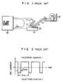
- Fig. 1 is a diagram schematically showing a welding apparatus conventionally used for automatic TIG welding of aluminum or aluminum alloys.
- an AC arc 7 is formed with a base metal 6 by an AC arc power supply 16, a TIG torch 4 and tungsten electrode 5, and a filler wire 9 is guided to the weld zone through a conduit 10 by use of a wire supply unit 8.
- the weld zone is thus fused by the arc 7 thereby to form a deposited bead 13.
- a water cooling system and a shield gas system for the torch 4 are not shown.
- An inert gas such as argon gas is caused to flow out of the torch 4 to shield the weld zone.
- the AC arc 7 is used to allow a period to form a negative pole of the arc at the base metal 6 and an oxide in the surface of the base metal 6 is broken by the impact of ions entering the negative pole in what is called "the cleaning action".
- the TIG welding process conducted while removing an oxide film this way is the most common practice for welding aluminum.
- the TIG welding of copper or copper alloys commonly uses a DC electrode negative polarity.
- the welding process is facilitated by the use of an AC arc producing the cleaning action.
- a deposited metal is generally formed by melting with the arc a filler wire made of what is called a "cold wire" which is not heated by conduction of electricity.
- An AC TIC arc power supply for producing a square wave AC current by switching a DC current is often used as a power supply for arc.
- An example of such an arc current designated by i A is shown in Fig. 2.
- the period of this waveform is set to 7 ms, of which the term of, say, 1 ms of the half wave of the electrode positive polarity, forming a negative pole of the base metal, is adjusted to approximately 1.5 ms length thereby regulating the degree of the cleaning action of the arc.
- the hot wire TIG welding process is often used in combination with the DC TIG welding process for carbon steel, stainless steel or the like.
- This process uses as a wire heating current a DC or AC (Reference: Hot Wire; J.F. Saenger; Welding and Metal Fabrication, June 1971, or a DC pulse (USP. 4,614,856) for protection against arc magnetic blow.
- a mere combination of a hot-wire heating power supply with the AC TIG arc poses the problem of unstable arc and the resulting inapplicability of the hot-wire welding.
- a study of the cause of this problem in aluminum welding has revealed that when the unconsumable electrode is positive producing the cleaning effect, the arc wanders seeking an oxide in the base metal surface (Reference: Welding Arc Phenomena; Kohei Ando, et al.; July 1962, p. 141 to 144), and if the wire is supplied with current during this time, the magnetic blow of the arc due to the magnetic field generated by the wire current aggravates the arc instability with the result that the arc is liable to be interrupted.
- EP-A-0139249 discloses a hot-wire TIG welding method and an apparatus therefor, wherein only D.C. arc power supply is used.
- the wire heating electric power is detected and the output of the wire heating power supply is controlled while making a reference to the detected value of the wire heating electric power such that the latter commensurate with the wire feed speed is obtained.
- said power is controlled through the control of the time of supply of the wire heating current in each base arc current period in which the arc current takes the base level.
- the primary object of the present invention is to provide an unconsumable-electrode welding apparatus which is efficient, high in welding rate and superior in practical applications without any unstable phenomenon such as arc interruptions or magnetic blow.
- Another object of the present invention is to provide an unconsumable-electrode welding apparatus which is high in both quality and economic value with an improved welded joint by narrower heat-affected zone.
- an unconsumable-electrode welding apparatus such as a hot-wire AC TIG welding apparatus comprising an unconsumable electrode such as tungsten arranged in opposedly spaced relationship with a base metal to be welded, an AC arc welding power supply connected between the base metal and the unconsumable electrode, a filler wire such as aluminum fed toward an arc-generated part formed between the base metal and the unconsumable electrode, and wire feed means for feeding the filler wire.
- the welding apparatus described above further comprises a wire-heating power supply for producing a pulsed current.
- This heating power supply is adapted to heat the filler wire by applying a pulsed current thereto in response to a synchronous signal from the AC arc power supply or a signal produced by detection of an arc current or an arc voltage of the AC arc power supply.
- a heating current in pulse form is applied to the filler wire thereby to heat the same during the period when the unconsumable electrode remains negative due to the AC arc formed between the unconsumable electrode and the base metal.
- the wire is not supplied with any current, or is heated with a sufficiently small current as not to substantially cause any magnetic blow.
- FIG. 3 A configuration of an AC TIG welding apparatus using hot wire according to a first embodiment of the present invention is shown schematically in Fig. 3.
- Numeral 1 designates a welding power supply including a square wave AC arc current generation circuit 2 and a wire current generation circuit 3 for producing a pulsed current.
- the wire current generation circuit 3 makes up a wire heating power supply for producing a pulsed current in synchronism with the AC arc current generation circuit 2.
- Numeral 4 designates a TIG torch, and numeral 5 a tungsten electrode constituting an unconsumable electrode which forms an arc 7 with a base metal 6.
- Numeral 8 designates a wire feeder unit for feeding a filler wire 9 which is guided to a weld zone by a conduit 10 into contact with the base metal 6.
- the conduit 10 has at the forward end thereof a contact tip 11 connected to one of the wire current output terminals of the welding power supply 1.
- FIG. 4 is a diagram showing a specific circuit of the welding power supply 1 in Fig. 3.
- An output circuit for a square wave AC arc current i A includes a DC voltage generation circuit 21 having a full-wave rectification diode DA1 and a capacitor C1, a primary transistor switching circuit 22 with transistors Tr1 to Tr4 for switching and converting a voltage generated by the DC voltage generation circuit 21 into an alternating current of appoximately 20 kHz, a large current DC circuit 23 with a transformer T1 for transforming the alternating current from the switching circuit 22, diodes D1, D2 for rectifying the transformed voltage and a coil L1 for smoothing the rectified voltage thereby to produce a large direct current, a secondary transistor switching circuit 24 with a bridge of transistors Tr5 to Tr8 for producing a square wave alternating current of about 100 Hz from the DC output of the large direct current circuit 23, a primary control signal generation circuit 25 for producing a control signal for the primary transistor switching circuit 22, and a secondary control signal generation circuit 26 for producing a
- the DC pulsed current output circuit for the wire heating power supply includes a primary transistor switching circuit 28 with transistors Tr9 and Tr10 for switching and converting the voltage from the DC voltage generation circuit 27 into an AC voltage of about 20 kHz, a DC pulsed current generation circuit 29 with a transformer T2 for transforming the AC voltage from the primary transistor switching circuit 28, diodes D3, D4 for rectifying the transformed voltage and a coil L2 for smoothing the rectified voltage thereby to produce a DC pulsed current, and a control signal generation circuit 30 for producing a control signal for the primary transistor switching circuit 28.
- the arc current i A and an output waveform thereof are controlled by the primary control signal generation circuit 25 for the primary transistor switching circuit 22 and the secondary control signal generation circuit 26 for the secondary transistor switching circuit 24.
- the energization period of a positive half wave and a negative half wave of a square wave alternating current is determined in producing an output.
- An associated synchronous signal is applied also to a control signal generation circuit 30 for the primary transistor switching circuit 28 of the wire heating output circuit thereby to produce a pulsed current i W for wire energization in synchronism with the arc current waveform.
- the primary control signal generation circuit 25 for the primary transistor switching circuit 22 is mainly comprised of integrated circuits for a switching regulator and produces a pulse width control signal for producing an arc current corresponding to a reference voltage from an external source.
- Fig. 5 is a diagram schematically showing a configuration of the secondary control signal generation circuit 26 and the control signal generation circuit 30 shown in Fig. 4.
- the secondary control signal generation circuit 26 includes an astable multivibrator 26-1 and a monostable multivibrator 26-2 as main components.
- the "high” and “low” periods of this circuit are regulated by variable resistors 31, 32.
- Corresponding energization periods of the positive and negative half waves of the square wave alternating current are determined and applied to the secondary transistor switching circuit 24. Also, this signal is applied to the control signal generation circuit 30.
- the control signal generation circuit 30 in order to obtain an effective current suitable for a wire feed rate, generates at a sawtooth waveform generation circuit 33-3 thereof a sawtooth wave synchronous with the phase of the AC arc current from the signal of the secondary control signal generation circuit 26, which sawtooth wave is compared with the output from a pulse width regulation variable resistor 33 at a comparator 33-1.
- a high frequency of such as 20 kHz is generated by a oscillator 33-4 and a D-type flip-flop 33-2 and the logical product of this high frequency and the output of the comparator 33-1 is produced from NAND gates 33-5 and 33-6.
- a turn-on signal is produced from the control signal generation circuit 30 to the primary transistor switching circuit 28 in synchronism with the phase of the AC arc current when the tungsten electrode turns negative thereby to produce a pulse current for heating the wire.
- Figs. 6(a) and (b) show examples of an arc current waveform i A (Fig. 6(a)) and a wire current waveform i W (Fig. 6(b)) respectively produced at the time of hot-wire welding of aluminum by a welding apparatus according to the present invention.
- An aluminum wire 1.2 mm in diameter is used as a filler wire 9 with the effective current set at 200 A, electrode negative period of the arc current at 7 ms and the period of electrode positive polarity at 3 ms.
- the wire current i W is provided by a pulsed current with a peak value of 500 A which is supplied for a period of 1.5 ms from the time point when the arc reaches an electrode negative state.
- the wire is energized this way only when the arc is electrode negative polarity, so that arc interruptions during wire energization are eliminated and a satisfactory welding bead is formed with the an aluminum wire of 1.2 mm in diameter fed at the rate of 4 m/min.
- Table 1 shows a specification of the butt welding conducted on an aluminum plate 3 mm in thickness by use of the welding apparatus shown in Fig. 3 to determine conditions capable of welding while forming a beautiful reverse side bead with the same arc current. As a seen, a welding rate as high as 1.3 times higher is attained for the hot-wire welding process than for the cold TIG welding process.
- Table 1 Item Cold TIG Hot-wire TIG Arc current 180 A 180 A Wire current (effective value) 0 A 94 A Wire feed rate 1.0 m/min 1.5 m/min Welding rate 300 mm/min 400 mm/min Base metal 5083-0, 3 mm thick Wire 4043 WY, ⁇ 1.6 mm
- the arc current takes an AC waveform of almost a simple square wave. Since the arc current has a high value during the wire energization period, the arc is subjected to a magnetic blow for a longer time with the lengthening of the wire energization period as a result of an increased wire feed rate, thus preventing the fusion of the base metal to a greater degree.
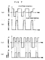
- Figs. 7(a), (b), (c) and (d) are diagrams showing an arc current waveform i A and a wire current waveform i W according to a second embodiment of the invention comprising means for protection against the above-mentioned problem.
- the arc current is kept at about 50 A or a low current value barely maintaining an arc during a part, say, 3 ms of the wire energization period contained in an electrode negative wave.
- the wire is supplied with a current with as high a peak as required for melting the wire, while during the period when the wire is not energized, the arc current is increased to produce an arc current i A for melting the base metal.
- the welding work is not substantially affected by a sharp magnetic blow which may occur while the arc current is low.
- the hot-wire AC TIG welding process is accomplished even with a high wire melting rate.
- the wire begins to be energized immediately after the arc current takes an electrode negative half waveform.
- the wire is energized some time after an arc is formed such as that shown in Fig. 7(c) and Fig. 7(d), with an arc current of an electrode negative half wave.
- the filler wire is energized at all times during the period when an unconsumable electrode forms a negative pole.
- the present invention is not limited to such a case, but a very small current not causing a magnetic blow may be supplied when an unconsumable electrode turns positive with a similar effect.
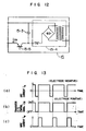
- FIG. 8A and 8B show examples of an arc current waveforms (Fig. 8A(a), Fig. 8B(a)) and wire current waveforms (Figs. 8A(b), Fig. 8B(b)) with the wire energized by a current of such a value as to not substantially cause a magnetic blow during a half wave period of electrode positive polarity.
- the first embodiment has been explained with reference to a case in which an AC arc welding power supply is integrally constructed with a wire heating power supply.
- the wire heating power supply may be formed as a circuit independent of the arc power supply so that a wire heating current may be produced in synchronism with an arc current in response to an AC output of the sync signal from the arc power supply without departing from the spirit of the present invention.
- an output voltage or an output current may be detected from an arc power supply, and a wire current may be produced in synchronism with the arc current.
- Fig. 9 is a diagram for explaining a third embodiment of the present invention, in which an arc current is detected from an arc power supply 16 by an arc current detector 14 including a Hall element, and the output of a wire heating power supply 15 is controlled in synchronism with the detected signal.
- This configuration permits the existing AC arc power supply 16 to be used and a hot-wire AC TIG welding apparatus is very economically constructed only by adding a wire heating power supply 15.
- the filler wire 9 is in contact with the base metal 6.
- an arc current flows through a route including the tungsten electrode 5, the arc 7 and the base metal 6 in that order and also through a route including the tungsten electrode 5, the filler wire 9, the DC pulsed current generation circuit 29 and the base metal 6.
- an arc is caused also from the filler wire 9, thereby disturbing the arc and hampering a smooth progress of the welding operation.
- Fig. 10 shows a configuration of the wire heating power supply 15 for solving the above-mentioned problem according to a fourth embodiment of the present invention.
- a transistor 15-5 is connected making up a switching element at the output of a DC pulse current generation circuit 29.
- Character B designates an arc current cut-off circuit which turns off the transistor 15-5 to prevent the arc current from flowing into the filler wire 9 when the filler wire 9 is separated from the base metal 6.
- Figs. 11A, 11B and 11C show other configurations of the wire heating power supply 15 according to the fourth embodiment of Fig. 10.
- the configuration of Fig. 11A has inserted therein thyristors 15-1 which are capable of performing dual functions as diodes of the DC pulse current generation circuit 29 and as transistor 15-5.
- the circuit of Fig. 11B is configured to be controlled by a triac 15-2 making up a phase control device for generating a wire pulse current.
- Fig. 11C shows a circuit configured with only of the thyristors 15-1 after transformation of an input at a transformer. All these configurations attain the same effect as the fourth embodiment shown in Fig. 10.
- Fig. 12 shows another configuration of the wire heating power supply 15 according to the fourth embodiment.
- the output of a DC generation circuit 15-4 is charged in a capacitor 15-3, and the transistor 15-5 is switched to form a pulsed current through the discharge of the capacitor 15-3.
- the same effect as in the fourth embodiment shown in Fig. 10 is attained also by this embodiment.
- Figs. 13(a), (b) and (c) show an arc current (Fig. 13(a)), a control signal for the transistor 15-5 (Fig. 13(b)) and a wire current (Fig. 13(c)) respectively for the hot-wire welding process using the welding apparatus shown in Fig. 10.
- An AC TIG welding apparatus of a square waveform is used as the arc power supply 16 in Fig. 10, and a negative output of the wire heating power supply 15 is connected to the filler wire 9 and a positive output thereof to the base metal 6.
- the wire is controlled to be energized only during the negative stage of the tungsten electrode 5.
- the filler wire 9 is away from the base metal 6 when the tungsten electrode 5 is positive, an arc current is ready to flow into the wire 6 through a route including the tungsten electrode 5, filler wire 9, DC pulse current generation circuit 29 and the base metal 6.
- the transistor 15-5 is thus controlled to turn off during this period (when the tungsten electrode 5 is positive).
- the route including the tungsten electrode 5, filler wire 9, DC pulse current generation circuit 29 and the base metal in that order is cut off, so that even when the filler 9 separated from 6 and floats in the arc 7, the arc current is prevented from flowing into the filler wire 9.
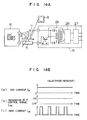
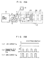
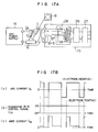
- Figs. 14A, 15A and 16A show the routes of the arc current i A with the filler wire 9 separated from the base metal 6 under the conditions mentioned below in Fig. 10, and Figs. 14B, 15B and 16B an arc current waveform (a), a transistor 15-5 control signal (b) and a wire current waveform (b) respectively associated therewith.
- a DC TIG welding apparatus is used as an arc power supply of Fig. 10 with the tungsten electrode 5 connected to a negative terminal and the base metal 6 to a positive terminal.
- the negative output terminal of the wire heating power supply 15 is connected to the filler wire 9, and the positive terminal thereof to the base metal 6.
- the filler wire 9 is separated from the base metal 6 when the transistor 15-5 is turned on in this connection.
- the transistor 15-5 is not required to turn on/off but may always be kept on.
- a DC TIG welding apparatus is used as an arc power supply 16 of Fig. 10 with the tungsten electrode 5 connected to the negative terminal and the base metal to the positive terminal.
- the positive output terminal of the wire heating power supply 15 is connected to the filler wire 9, and the negative terminal thereof to the base metal 6. If the filler wire 9 is separated from the base metal 6 with the transistor 15-5 turned on in this connection, the arc current i A is liable to flow through the route including the base metal 6, DC pulse current generation circuit 20, transistor 15-5, filler wire 9 and the tungsten electrode 5 in that order.
- the transistor 15-5 is kept off.
- an AC TIG welding apparatus is used as an arc power supply 16 in Fig. 10 with the negative output terminal of the wire heating power supply 15 connected to the filler wire 9 and the positive terminal thereof to the base metal 6. If the filler wire 9 is separated from the base metal 6 with the transistor 15-5 turned on in this connection during the positive state of the tungsten electrode 5, the arc current i A is liable to flow into the filler wire 9 through a route including the tungsten electrode 5, filler wire 9, DC pulse current generation circuit 29, transistor 15-5 and the base metal 6 in that order. As a result, during the period when it is not desirable to heat the wire by energization with the filler wire 9 separated from the base metal 6, for instance, the transistor 15-5 is turned off.
- an AC TIG welding apparatus is used as an arc power supply of Fig. 10 with the positive output terminal of the wire heating power supply 15 connected to the filler wire 9 and the negative output terminal thereof to the base metal 6. If the filler wire 9 is detached from the base metal when the transistor is turned on with the tungsten electrode 5 in negative state, part of the arc current i A is liable to flow into the filler wire 9 through the route including the base metal 6, DC pulse current generation circuit 29, transistor 15-5, filler wire 9 and the tungsten electrode 5 in that order.
- the diodes inserted in the DC pulse current generation circuit 29 prevent the arc current i A from flowing into the filler wire 9 and therefore the welding process is not effected substantially.
- the transistor 15-5 is turned off.
- the aforementioned embodiments refer principally to the case of aluminum welding.
- the base metal and the filler wire according to the present invention are not limited to aluminum, aluminum bronze or bellyrium bronze, but are applicable with equal effect to the hot-wire AC TIG welding process for welding mild steel, carbon steel, low-alloy steel, stainless steel or other high alloys.
- the arc in an inert gas ambient wanders seeking an oxide liable to form a negative pole during the half wave period of electrode positive polarity. The arc is therefore stabilized more by cutting off wire current during such a period.
- the present invention is not confined to the tungsten electrode used as an unconsumable electrode in the above-mentioned embodiments. Instead, other unconsumable electrodes such as carbon may be also used with equal effect.
- the present invention has been described above with reference to the AC TIG welding process, but is also applicable to the AC arc welding processes such as MAG (Metal Active Gas), MIG (Metal Inert Gas) or submerged arc welding for a hot-wire welding with high operating efficiency.
- MAG Metal Active Gas
- MIG Metal Inert Gas
- submerged arc welding for a hot-wire welding with high operating efficiency.
- the arc current flowing in the molten metal and the wire current flowing in pulse form function to vibrate the molten pool, so that the blowholes in the molten pool are liable to rise thereby reducing the case of blowholes being formed.
Landscapes
- Engineering & Computer Science (AREA)
- Physics & Mathematics (AREA)
- Plasma & Fusion (AREA)
- Mechanical Engineering (AREA)
- Arc Welding Control (AREA)
- Arc Welding In General (AREA)
Claims (15)
- Nichtabschmelzelektroden-Schweißvorrichtung mit einer Nichtabschmelzelektrode (5), die mit Abstand gegenüber einem zu schweißenden Basismetall (6) angeordnet ist, einer Wechselstrombogenschweißstromquelle (2), die zwischen dem Basismetall (6) und der Nichtabschmelzelektrode (5) angeschlossen ist, einem Fülldraht (9), der zu einem zwischen dem Basismetall (6) und der Nichtabschmelzelektrode (5) geformten Bogenerzeugungsteil gefördert wird, Drahtfördermitteln (8) zum Fördern des Fülldrahtes (9) und einer Wechselstrom-TIG-Schweißeinrichtung mit einer Drahterhitzungsstromquelle (3) zum Speisen des Fülldrahtes (9),
dadurch gekennzeichnet,
daß die Drahterhitzungsstromquelle (3) den Fülldraht (9) durch Zuführen eines gepulsten Stroms synchron mit der Phase des Wechselstrombogenstroms iA erhitzt, der zwischen der Nichtabschmelzelektrode (5) und dem Basismetall (6) gebildet wird, der Fülldraht (9) durch Zuführen eines Drahterhitzungsstroms iW während der Periode erhitzt wird, wenn die Nichtabschmelzelektrode (5) durch einen zwischen der Nichtabschmelzelektrode (5) und dem Basismetall (6) gebildeten Wechselstrombogen (7) bei negativer Polarität gehalten wird, und wahlweise der Drahterhitzungsstrom iW unterbrochen oder der Fülldraht (9) durch Zuführen eines genügend schwachen Stroms, um keine wesentliche magnetische Blaswirkung zu verursachen, während der Periode erhitzt wird, wenn die Nichtabschmelzelektrode (5) durch den Wechselstrombogen (7) bei positiver Polarität gehalten wird. - Wechselstrom-TIG-Schweißeinrichtung mit Verwendung eines heißen Drahtes nach Anspruch 1,
dadurch gekennzeichnet,
daß die Länge der Zeit der Speisung des Fülldrahts (9) mit dem Impulsstrom kürzer als die Periode ist, wenn die Nichtabschmelzelektrode (5) bei negativer Polarität gehalten wird. - Wechselstrom-TIG-Schweißeinrichtung mit Verwendung eines heißen Drahtes nach Anspruch 1,
dadurch gekennzeichnet,
daß der Fülldraht (9) im wesentlichen zu der gleichen Zeit zu speisen ist, wenn die Nichtabschmelzelektrode (5) von negativer Polarität wird. - Wechselstrom-TIG-Schweißeinrichtung mit Verwendung eines heißen Drahtes nach Anspruch 1,
dadurch gekennzeichnet,
daß die Impulsbreite des von der Drahterhitzungsstromquelle (3) erzeugten gepulsten Stroms entsprechend den Schweißbedingungen einstellbar ist. - Wechselstrom-TIG-Schweißeinrichtung mit Verwendung eines heißen Drahtes nach Anspruch 1,
dadurch gekennzeichnet,
daß die Periode, wenn die Nichtabschmelzelektrode (5) bei negativer Polarität gehalten wird, in eine Basisperiode eines niedrigen Bogenstromwertes und eine Spitzenperiode hohen Bogenstromwertes unterteilt wird, wobei der Fülldraht (9) während der Basisperiode gespeist wird. - Wechselstrom-TIG-Schweißeinrichtung mit Verwendung eines heißen Drahtes nach Anspruch 1,
dadurch gekennzeichnet,
daß ein gepulster Strom von der Drahterhitzungsstromquelle entsprechend einem Synchronsignal von der Wechselstrombogenschweißstromquelle (2) erzeugt wird. - Wechselstrom-TIG-Schweißeinrichtung mit Verwendung eines heißen Drahtes nach Anspruch 1,
dadurch gekennzeichnet,
daß sie weiter Erfassungsmittel zum wahlweisen Erfassen eines Bogenstroms oder einer Bogenspannung der Wechselstrombogenschweißstromquelle (2) aufweist, wobei die Drahterhitzungsstromquelle (3) einen gepulsten Strom synchron mit dem Erfassungssignal von den Erfassungsmitteln erzeugt. - Wechselstrom-TIG-Schweißeinrichtung mit Verwendung eines heißen Drahtes nach Anspruch 1,
dadurch gekennzeichnet,
daß der Fülldraht (9) wahlweise aus Aluminium oder einer Aluminiumlegierung besteht. - Wechselstrom-TIG-Schweißeinrichtung mit Verwendung eines heißen Drahtes nach Anspruch 1,
dadurch gekennzeichnet,
daß die Drahterhitzungsstromquelie (3) einen Bogenstromsperrkreis zum Verhindern eines Fließens des Bogenstroms iA in den Fülldraht (9) aufweist. - Wechselstrom-TIG-Schweißeinrichtung mit Verwendung eines heißen Drahtes nach Anspruch 2,
dadurch gekennzeichnet,
daß der Fülldraht (9) im wesentlichen zu der gleichen Zeit zu speisen ist, wenn die Nichtabschmelzelektrode (5) von negativer Polarität wird. - Wechselstrom-TIG-Schweißeinrichtung mit Verwendung eines heißen Drahtes nach Anspruch 9,
dadurch gekennzeichnet,
daß der Bogenstromsperrkreis so betrieben wird, daß der Bogenstrom iA unterbrochen wird, nachdem der Strom zum Speisen des Fülldrahtes (9) auf Null verringert ist. - Nichtabschmelzelektroden-Schweißvorrichtung nach Anspruch 1,
dadurch gekennzeichnet,
daß die Drahterhitzungsstromquelle (3) Speisungssteuerelemente (Tr₉ und Tr₁₀, 15-1, 15-2) und Steuermittel (30) aufweist, denen ein Phasenumformungssignal der Wechselstrombogenschweißstromquelle (2) zugeführt wird;
der Fülldraht (9) mit der Einschaltperiode der gesteuerten Speisungssteuerelemente während der Periode erhitzt wird, wenn die Nichtabschmelzelektrode (5) bei negativer Polarität bleibt; und
die Speisungssteuerelemente wahlweise zum Unterbrechen der Speisung des Fülldrahtes (9) oder zum Speisen des Fülldrahtes (9) mit einem genügend schwachen Strom, um keine wesentliche magnetische Blaswirkung zu verursachen, gesteuert werden. - Wechselstrom-TIG-Schweißeinrichtung mit Verwendung eines heißen Drahtes nach Anspruch 1,
dadurch gekennzeichnet,
daß die Dauer negativer Polarität der Nichtabschmelzelektrode der Wechselstrombogenschweißstromquelle in eine Basisperiode mit einem niedrigen Bogenstromwert und eine Spitzenperiode mit einem hohen Bogenstromwert unterteilt wird, wobei die Speisungssteuerelemente durch die Steuermittel in solcher Weise gesteuert werden, um den Fülldraht (9) durch dessen Speisung während der Basisperiode zu erhitzen. - Wechselstrom-TIG-Schweißeinrichtung mit Verwendung eines heißen Drahtes nach Anspruch 1,
dadurch gekennzeichnet,
daß sie weiter Erfassungsmittel (14) zum wahlweisen Erfassen des Bogenstroms oder der Bogenspannung der Wechselstrombogenschweißstromquelle aufweist, wobei die Steuermittel die Speisungssteuerelemente auf der Basis eines diesen von den Erfassungsmitteln zugeführten Ausgangs steuern. - Wechselstrom-TIG-Schweißeinrichtung mit Verwendung eines heißen Drahtes nach Anspruch 1,
dadurch gekennzeichnet,
daß die Drahterhitzungsstromquelle (3) einen Bogenstromsperrkreis mit Speisungssteuerelementen (15-5, 15-1, 15-2) aufweist, die dadurch abgeschaltet werden, um den Stromeingang zum Draht während der Periode, wenn die Nichtabschmelzelektrode bei positiver Polarität bleibt, zu unterbrechen, wobei die Speisungssteuermittel (15-5, 15-1, 15-2) nur während der negativen Polarität der Nichtabschmelzelektrode eingeschaltet werden, wenn der Bogenstrom nicht in den Draht fließt.
Applications Claiming Priority (2)
| Application Number | Priority Date | Filing Date | Title |
|---|---|---|---|
| JP290550/87 | 1987-11-19 | ||
| JP62290550A JPH01133680A (ja) | 1987-11-19 | 1987-11-19 | 非消耗電極溶接装置 |
Publications (3)
| Publication Number | Publication Date |
|---|---|
| EP0316936A2 EP0316936A2 (de) | 1989-05-24 |
| EP0316936A3 EP0316936A3 (en) | 1989-07-05 |
| EP0316936B1 true EP0316936B1 (de) | 1992-08-26 |
Family
ID=17757481
Family Applications (1)
| Application Number | Title | Priority Date | Filing Date |
|---|---|---|---|
| EP88119216A Expired - Lifetime EP0316936B1 (de) | 1987-11-19 | 1988-11-18 | AC-WIG-Schweissgerät mit heissem Draht |
Country Status (5)
| Country | Link |
|---|---|
| US (1) | US4904843A (de) |
| EP (1) | EP0316936B1 (de) |
| JP (1) | JPH01133680A (de) |
| KR (1) | KR910003861B1 (de) |
| DE (1) | DE3874091T2 (de) |
Families Citing this family (52)
| Publication number | Priority date | Publication date | Assignee | Title |
|---|---|---|---|---|
| GB9021237D0 (en) * | 1990-09-29 | 1990-11-14 | Rolls Royce Plc | A method of welding,a method of applying a metallic wear resistant coating to a metallic substrate and a method of sealing a hole in a metallic substrate |
| US5466905A (en) * | 1994-04-05 | 1995-11-14 | General Electric Company | Low electric D.C., low time rate polarity reversing arc welding method |
| US5464958A (en) * | 1994-04-05 | 1995-11-07 | General Electric Company | Arc welding apparatus with variable polarity reversing device and control |
| US5601741A (en) * | 1994-11-18 | 1997-02-11 | Illinois Tool Works, Inc. | Method and apparatus for receiving a universal input voltage in a welding power source |
| JP3565985B2 (ja) * | 1996-04-26 | 2004-09-15 | 愛知産業株式会社 | 半自動tig溶接装置 |
| JP3284930B2 (ja) * | 1997-07-09 | 2002-05-27 | 株式会社日立製作所 | 高周波パルスアーク溶接法とその装置及び用途 |
| US6111216A (en) * | 1999-01-19 | 2000-08-29 | Lincoln Global, Inc. | High current welding power supply |
| AT411442B (de) * | 2001-02-09 | 2004-01-26 | Fronius Schweissmasch Prod | Verfahren zum löten von werkstücken |
| US6689988B2 (en) * | 2001-09-28 | 2004-02-10 | Illinois Tool Works Inc. | Welding gun having a plated tip and method for making same |
| US20040179923A1 (en) * | 2002-12-23 | 2004-09-16 | Lockheed Martin Corporation | Automated transportation mechanism for conveyence and positioning of test containers |
| US9956639B2 (en) * | 2005-02-07 | 2018-05-01 | Lincoln Global, Inc | Modular power source for electric ARC welding and output chopper |
| US8581147B2 (en) * | 2005-03-24 | 2013-11-12 | Lincoln Global, Inc. | Three stage power source for electric ARC welding |
| US8785816B2 (en) | 2004-07-13 | 2014-07-22 | Lincoln Global, Inc. | Three stage power source for electric arc welding |
| US8269141B2 (en) | 2004-07-13 | 2012-09-18 | Lincoln Global, Inc. | Power source for electric arc welding |
| US9855620B2 (en) | 2005-02-07 | 2018-01-02 | Lincoln Global, Inc. | Welding system and method of welding |
| FR2882670A1 (fr) * | 2005-03-04 | 2006-09-08 | Air Liquide | Procede et installation de soudage mig pulse a forte intensite |
| US9647555B2 (en) * | 2005-04-08 | 2017-05-09 | Lincoln Global, Inc. | Chopper output stage for arc welder power source |
| US9259796B2 (en) * | 2006-01-17 | 2016-02-16 | Lincoln Global, Inc. | Synergic TIG welding system |
| KR100829545B1 (ko) * | 2007-05-23 | 2008-05-14 | 웰메이트 주식회사 | 비소모식 아크 용접 장치 및 용접 동작 프로파일 프로그램방법 |
| US10086461B2 (en) | 2009-01-13 | 2018-10-02 | Lincoln Global, Inc. | Method and system to start and use combination filler wire feed and high intensity energy source for welding |
| US9085041B2 (en) | 2009-01-13 | 2015-07-21 | Lincoln Global, Inc. | Method and system to start and use combination filler wire feed and high intensity energy source for welding |
| JP5581008B2 (ja) * | 2009-04-28 | 2014-08-27 | バブ日立工業株式会社 | Tig溶接装置 |
| CN102470474B (zh) * | 2010-02-23 | 2015-07-08 | 松下电器产业株式会社 | 交流电弧焊接方法及交流电弧焊接装置 |
| JP5234042B2 (ja) * | 2010-04-07 | 2013-07-10 | 株式会社デンソー | アーク溶接方法およびその装置 |
| US9283635B2 (en) * | 2012-03-02 | 2016-03-15 | Lincoln Global, Inc. | Synchronized hybrid gas metal arc welding with TIG/plasma welding |
| JP6043969B2 (ja) * | 2012-03-07 | 2016-12-14 | パナソニックIpマネジメント株式会社 | 溶接方法 |
| US9862050B2 (en) * | 2012-04-03 | 2018-01-09 | Lincoln Global, Inc. | Auto steering in a weld joint |
| US10239145B2 (en) * | 2012-04-03 | 2019-03-26 | Lincoln Global, Inc. | Synchronized magnetic arc steering and welding |
| US10183351B2 (en) | 2012-06-27 | 2019-01-22 | Lincoln Global, Inc. | Parallel state-based controller for a welding power supply |
| US20140001168A1 (en) * | 2012-06-27 | 2014-01-02 | Lincoln Global, Inc. | Parallel state-based controller for a welding power supply |
| BR112015000607A2 (pt) * | 2012-07-12 | 2017-06-27 | Lincoln Global Inc | método e sistema para iniciar e usar em combinação um alimentador de fio de adição e uma fonte de geração de arco para soldagem |
| BR112015003409B1 (pt) * | 2012-08-14 | 2018-12-04 | Esab Ab | método e sistema para soldagem por arco submerso |
| US10035211B2 (en) * | 2013-03-15 | 2018-07-31 | Lincoln Global, Inc. | Tandem hot-wire systems |
| US20140263231A1 (en) * | 2013-03-15 | 2014-09-18 | Lincoln Global, Inc. | Tandem hot-wire systems |
| US10086465B2 (en) * | 2013-03-15 | 2018-10-02 | Lincoln Global, Inc. | Tandem hot-wire systems |
| US10399172B2 (en) * | 2013-06-26 | 2019-09-03 | Lincoln Global, Inc. | System and method for hot wire arc steering |
| KR101698802B1 (ko) * | 2013-08-20 | 2017-01-24 | 부경대학교 산학협력단 | 티그 용접용 용가재 |
| US10464168B2 (en) | 2014-01-24 | 2019-11-05 | Lincoln Global, Inc. | Method and system for additive manufacturing using high energy source and hot-wire |
| CN104308327A (zh) * | 2014-10-27 | 2015-01-28 | 西安航空动力股份有限公司 | 一种防止零件堆焊耐磨层缺陷的工艺方法 |
| CN104907716B (zh) * | 2015-07-02 | 2017-03-01 | 哈尔滨工业大学(威海) | 一种等离子弧与mig电弧距离可调式智能复合焊炬 |
| US10675699B2 (en) * | 2015-12-10 | 2020-06-09 | Illinois Tool Works Inc. | Systems, methods, and apparatus to preheat welding wire |
| WO2017135080A1 (ja) * | 2016-02-04 | 2017-08-10 | パナソニックIpマネジメント株式会社 | パルスアーク溶接制御方法およびパルスアーク溶接装置 |
| US10994371B2 (en) * | 2016-02-24 | 2021-05-04 | Mitsubishi Electric Research Laboratories, Inc. | System and method for depositing a metal to form a three-dimensional part |
| US11027362B2 (en) | 2017-12-19 | 2021-06-08 | Lincoln Global, Inc. | Systems and methods providing location feedback for additive manufacturing |
| US20200246901A1 (en) * | 2019-02-06 | 2020-08-06 | Lincoln Global, Inc. | Tig welding arc initiation |
| KR20200102880A (ko) | 2019-02-22 | 2020-09-01 | 강성귀 | 인버터식 아르곤가스 용접기 |
| CN110508909B (zh) * | 2019-08-07 | 2021-07-09 | 哈电集团(秦皇岛)重型装备有限公司 | 不锈钢管对接自动叠加脉冲单道焊的焊接系统和方法 |
| US20210060685A1 (en) * | 2019-08-30 | 2021-03-04 | Illinois Tool Works Inc. | Methods and apparatus to provide welding-type power and preheating power |
| CN111515499A (zh) * | 2020-01-02 | 2020-08-11 | 北京理工大学 | 一种不锈钢电弧增材制造装置及其工艺 |
| DE102020207573A1 (de) * | 2020-06-18 | 2021-12-23 | Kjellberg-Stiftung | Verfahren zum Schweißen mit einem drahtförmigen Zusatzwerkstoff und mindestens einem Laserstrahl |
| USD952011S1 (en) * | 2020-11-17 | 2022-05-17 | Harry Wong | Tig feeder |
| CN114633005A (zh) * | 2022-04-02 | 2022-06-17 | 山东电力工业锅炉压力容器检验中心有限公司 | 一种钨极氩弧焊的冷热丝焊枪和焊接方法 |
Family Cites Families (6)
| Publication number | Priority date | Publication date | Assignee | Title |
|---|---|---|---|---|
| JPS56131071A (en) * | 1980-03-18 | 1981-10-14 | Ishikawajima Harima Heavy Ind Co Ltd | All position tig welding method |
| DE3213278A1 (de) * | 1981-04-10 | 1982-11-18 | Mitsubishi Denki K.K., Tokyo | Mit kurzschluss arbeitende lichtbogen-uebertragschweissmaschine |
| JPS58119471A (ja) * | 1982-01-11 | 1983-07-15 | Mitsubishi Electric Corp | ホツトワイヤ式ア−ク溶接機 |
| DE3482097D1 (de) * | 1983-09-27 | 1990-06-07 | Babcock Hitachi Kk | Vorrichtung zum wolfram-inert-gas-schweissen mit erwaermtem zufuehrdraht. |
| JPS6082278A (ja) * | 1983-10-07 | 1985-05-10 | Babcock Hitachi Kk | ホツトワイヤtig溶接装置 |
| JP2610819B2 (ja) * | 1985-12-04 | 1997-05-14 | バブコツク日立株式会社 | ホツトワイヤtig溶接装置 |
-
1987
- 1987-11-19 JP JP62290550A patent/JPH01133680A/ja active Pending
-
1988
- 1988-10-29 KR KR1019880014146A patent/KR910003861B1/ko not_active Expired
- 1988-11-16 US US07/271,880 patent/US4904843A/en not_active Expired - Lifetime
- 1988-11-18 DE DE8888119216T patent/DE3874091T2/de not_active Expired - Fee Related
- 1988-11-18 EP EP88119216A patent/EP0316936B1/de not_active Expired - Lifetime
Also Published As
| Publication number | Publication date |
|---|---|
| DE3874091D1 (de) | 1992-10-01 |
| EP0316936A3 (en) | 1989-07-05 |
| KR910003861B1 (ko) | 1991-06-15 |
| EP0316936A2 (de) | 1989-05-24 |
| US4904843A (en) | 1990-02-27 |
| DE3874091T2 (de) | 1993-04-01 |
| JPH01133680A (ja) | 1989-05-25 |
| KR890007831A (ko) | 1989-07-06 |
Similar Documents
| Publication | Publication Date | Title |
|---|---|---|
| US4904843A (en) | AC TIG welding apparatus using hot wire | |
| JP4739641B2 (ja) | 短絡アーク溶接用電源装置及びロボット溶接装置 | |
| US5932121A (en) | Welding method in the overhead and vertical positions | |
| Hori et al. | Development of hot wire TIG welding methods using pulsed current to heat filler wire–research on pulse heated hot wire TIG welding processes | |
| JP2000158132A (ja) | 短絡溶接機 | |
| JPWO1997043073A1 (ja) | 横向溶接方法及びその溶接装置 | |
| AU7220700A (en) | Arc welder and torch for same | |
| US9463521B2 (en) | Methods and apparatus for improved low current AC/DC TIG welding and starting | |
| US3071680A (en) | Arc welding | |
| JPS61186172A (ja) | ホットワイヤtig溶接方法および溶接装置 | |
| Street | Pulsed arc welding: an introduction | |
| JP2610819B2 (ja) | ホツトワイヤtig溶接装置 | |
| JPS6313672A (ja) | ホツトワイヤ溶接装置 | |
| JPS60223661A (ja) | ア−ク溶接法 | |
| JP3229014B2 (ja) | 交流非消耗電極アーク溶接装置および方法 | |
| JPH0679466A (ja) | ホツトワイヤ溶接装置 | |
| JPS5868474A (ja) | パルスア−ク溶接用電源 | |
| JPS58224070A (ja) | ア−ク溶接法 | |
| JPH0356146B2 (de) | ||
| JPS5927779A (ja) | ガスメタルア−ク溶接方法 | |
| JPS6356029B2 (de) | ||
| JPH0952175A (ja) | アルミニウムのアーク溶接方法及び装置 | |
| JPH0221909B2 (de) | ||
| JP2025068841A (ja) | 非消耗電極アーク溶接の溶接開始方法 | |
| JPH04123873A (ja) | ホツトワイヤtig溶接電源 |
Legal Events
| Date | Code | Title | Description |
|---|---|---|---|
| PUAI | Public reference made under article 153(3) epc to a published international application that has entered the european phase |
Free format text: ORIGINAL CODE: 0009012 |
|
| PUAL | Search report despatched |
Free format text: ORIGINAL CODE: 0009013 |
|
| AK | Designated contracting states |
Kind code of ref document: A2 Designated state(s): DE FR GB SE |
|
| AK | Designated contracting states |
Kind code of ref document: A3 Designated state(s): DE FR GB SE |
|
| 17P | Request for examination filed |
Effective date: 19890801 |
|
| 17Q | First examination report despatched |
Effective date: 19900918 |
|
| GRAA | (expected) grant |
Free format text: ORIGINAL CODE: 0009210 |
|
| RBV | Designated contracting states (corrected) |
Designated state(s): DE GB SE |
|
| AK | Designated contracting states |
Kind code of ref document: B1 Designated state(s): DE GB SE |
|
| REF | Corresponds to: |
Ref document number: 3874091 Country of ref document: DE Date of ref document: 19921001 |
|
| PLBE | No opposition filed within time limit |
Free format text: ORIGINAL CODE: 0009261 |
|
| STAA | Information on the status of an ep patent application or granted ep patent |
Free format text: STATUS: NO OPPOSITION FILED WITHIN TIME LIMIT |
|
| 26N | No opposition filed | ||
| EAL | Se: european patent in force in sweden |
Ref document number: 88119216.5 |
|
| REG | Reference to a national code |
Ref country code: GB Ref legal event code: IF02 |
|
| PGFP | Annual fee paid to national office [announced via postgrant information from national office to epo] |
Ref country code: GB Payment date: 20031112 Year of fee payment: 16 |
|
| PGFP | Annual fee paid to national office [announced via postgrant information from national office to epo] |
Ref country code: SE Payment date: 20031117 Year of fee payment: 16 |
|
| PGFP | Annual fee paid to national office [announced via postgrant information from national office to epo] |
Ref country code: DE Payment date: 20040130 Year of fee payment: 16 |
|
| PG25 | Lapsed in a contracting state [announced via postgrant information from national office to epo] |
Ref country code: GB Free format text: LAPSE BECAUSE OF NON-PAYMENT OF DUE FEES Effective date: 20041118 |
|
| PG25 | Lapsed in a contracting state [announced via postgrant information from national office to epo] |
Ref country code: SE Free format text: LAPSE BECAUSE OF NON-PAYMENT OF DUE FEES Effective date: 20041119 |
|
| PG25 | Lapsed in a contracting state [announced via postgrant information from national office to epo] |
Ref country code: DE Free format text: LAPSE BECAUSE OF NON-PAYMENT OF DUE FEES Effective date: 20050601 |
|
| EUG | Se: european patent has lapsed | ||
| GBPC | Gb: european patent ceased through non-payment of renewal fee |
Effective date: 20041118 |