EP0317032A1 - Crochet pour la fixation de gouttières - Google Patents
Crochet pour la fixation de gouttières Download PDFInfo
- Publication number
- EP0317032A1 EP0317032A1 EP88202589A EP88202589A EP0317032A1 EP 0317032 A1 EP0317032 A1 EP 0317032A1 EP 88202589 A EP88202589 A EP 88202589A EP 88202589 A EP88202589 A EP 88202589A EP 0317032 A1 EP0317032 A1 EP 0317032A1
- Authority
- EP
- European Patent Office
- Prior art keywords
- bracket
- bore
- nut
- supporting
- supporting part
- Prior art date
- Legal status (The legal status is an assumption and is not a legal conclusion. Google has not performed a legal analysis and makes no representation as to the accuracy of the status listed.)
- Granted
Links
- 238000003780 insertion Methods 0.000 claims abstract description 17
- 230000037431 insertion Effects 0.000 claims abstract description 17
- 230000004308 accommodation Effects 0.000 claims abstract description 4
- 230000013011 mating Effects 0.000 claims abstract 3
- 230000014759 maintenance of location Effects 0.000 claims abstract 2
- 230000008878 coupling Effects 0.000 claims description 8
- 238000010168 coupling process Methods 0.000 claims description 8
- 238000005859 coupling reaction Methods 0.000 claims description 8
- 230000002787 reinforcement Effects 0.000 description 2
- 230000000717 retained effect Effects 0.000 description 2
- 125000006850 spacer group Chemical group 0.000 description 2
- 238000006073 displacement reaction Methods 0.000 description 1
- 238000009826 distribution Methods 0.000 description 1
- 238000004519 manufacturing process Methods 0.000 description 1
- 239000000463 material Substances 0.000 description 1
- 238000000034 method Methods 0.000 description 1
- 238000009827 uniform distribution Methods 0.000 description 1
- XLYOFNOQVPJJNP-UHFFFAOYSA-N water Substances O XLYOFNOQVPJJNP-UHFFFAOYSA-N 0.000 description 1
Images

Classifications
-
- E—FIXED CONSTRUCTIONS
- E04—BUILDING
- E04D—ROOF COVERINGS; SKY-LIGHTS; GUTTERS; ROOF-WORKING TOOLS
- E04D13/00—Special arrangements or devices in connection with roof coverings; Protection against birds; Roof drainage ; Sky-lights
- E04D13/04—Roof drainage; Drainage fittings in flat roofs, balconies or the like
- E04D13/064—Gutters
- E04D13/072—Hanging means
- E04D13/0722—Hanging means extending mainly under the gutter
Definitions
- the invention relates to a bracket unit according to the preamble of Claim 1.
- bracket unit is known from German Patent Application 2,945,503.
- the supporting part comprises first and second parallel-running plate pieces for forming an insertion area for the end part of the bracket part, the distance between the first and second plate pieces being equal to the thickness of the end part of the bracket part.
- a downward-bent lip goes out from the second, top plate piece, in order to prevent displacement of the bracket part inserted into the supporting part.
- the second and third plate pieces have opposite the end with the spacer a bore for allowing through the bolt via the bore formed in the eaves section.
- the disadvantage of the known bracket unit is that when the distance between the second and third plate pieces is such that the bracket unit can be pushed easily over the eaves section after obtaining the correct positioning, in which the bores for the bolt are in line, in order to maintain the correct positioning, the bracket unit must be held fast, the bolt must be inserted through the bores, the bolt must be tightened in the nut, and the bolt or the nut must be retained to prevent them from turning at the same time. Since the user has to carry out various actions at the same time, often standing on a ladder, this constitutes an unsafe situation, while fixing the bracket unit to the roof takes a relatively long time.
- the bracket unit If the distance between the second and third plate pieces is such that the bracket unit is difficult to slide over the eaves section, the user will have difficulty in finding the correct position in which the bores for the bolt are in line with each other. This is relatively time-consuming and, in order to save time, the user could put his head above or below the eaves section to see whether and to what extent the bores are in line. However, this also constitutes an unsafe situation.
- bracket unit is suitable only for use on eaves sections which are of essentially the same thicknesses, so that a relatively large number of bracket units of various dimensions have to be manufactured and held in stock, which makes the cost of the known bracket unit relatively high.
- the object of the invention is to eliminate the disadvantages of the known bracket unit.
- bracket unit of the type referred to in the preamble to Claim 1 by means of the measures mentioned in the characterizing part of Claim 1. Since the nut is fitted in the supporting part in advance and cannot turn therein or be lost therefrom, the user needs only two parts when fitting the bracket unit on the roof: the bolt and the supporting part. Since the user can insert the bolt first through the bore in the eaves section, the user can quickly find the correct positioning of the supporting part. This means that the bracket unit can be fixed easily, safely and quickly to the roof.
- the bore of the supporting part for the passage of the bolt is preferably formed by a slot whose longitudinal axis runs essentially parallel to the longitudinal axis of the supporting part, and in which the nut nesting space extends below the slot for taking the nut so that it can slide in the lengthwise direction of the supporting part.
- a bore in an end part of the bracket part to be inserted into the supporting part can be designed as a slot, in order to permit sliding of the supporting part and/or the bracket part in the lengthwise direction of the supporting part and this end part before the bolt is tightened.
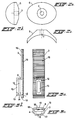
- the bracket unit according to the invention shown in Fig. 1, which is used with a corrugated sheet 1 of a roof, comprises an elongated supporting part 3 which is fitted against the bottom side of a corrugated ridge 2 of the corrugated sheet 1 and a bracket part 10 which is inserted into the supporting part 3, and a bottom end (not shown) of which is suitable for supporting a gutter (not shown).
- a nut 4 is fitted in the supporting part 3 in a manner which means that it cannot be turned or lost, as explained below.
- the corrugated ridge 2 has a hole (not shown), on which a washer 5 with a central bore 7 is placed when the bracket unit is being fixed to the corrugated sheet 1, for the purpose of passing through from the top a bolt 6 which can be screwed in the nut 4.
- the bottom side of the washer 5 is of a shape which is adapted to the top side of the corrugated ridge 2, in order to ensure uniform distribution of the pressure caused by tightening of the bolt 6.
- the projection of the washer in a plane running parallel to the corrugated sheet 1 is preferably an oval shape with a long main axis running at right angles to the corrugations of the corrugated sheet 1.
- the supporting part 3 has a first bore 8 (Fig. 3) which runs in the lengthwise direction of the supporting part 3 and has an insertion space for an elongated end part 9 of the bracket part 10.
- the end part 9 can be pushed so far into the bore 8 of the supporting part 3 that a bore 11 formed in the end part 9 is in line with the bore formed in the corrugated ridge 2 and a bore formed in the supporting part 3 (explained below) to allow the bolt 6 to pass through.
- the bore 11 is preferably an elongated shape in the lengthwise direction of the end part 9.
- Reinforcement and guide flanges 19 extend from the top side of the supporting part 3 which forms a supporting surface.
- the supporting part 3 has on the top side a recess 12 running in the lengthwise direction thereof (Figs. 1 and 3a).
- the bottom 13 of the recess 12 runs below the level of the bottom 14 of the bore 8.
- the dimensions of the recess 12 are suitable for placing on the bottom 13 thereof the nut 4 which, as shown, can have a square periphery, and which is retained at its other side by the end part 9 of the bracket part 10 inserted through the bore 8, in such a way that the nut 4 is accommodated in the recess 12 under the end part 9 so that it cannot turn or be lost.
- a bore 15 for passing through the bottom end of the bolt 6 is preferably provided in the bottom 13 of the recess 12, depending on the length of the bolt 6 used and the height of the supporting part 3.
- the recess 12 and the bore 15, if present, are preferably elongated in shape in the lengthwise direction of the supporting part 3, so that the nut 4 can be pushed between the end part 9 of the bracket part 10 inserted in the bore 8 and the bottom 13 of the recess 12 for easily obtaining a desired position of the supporting part 3 and/or of the bracket part 10 relative to the corrugated sheet 1.
- the bore 11 of the end part 9 of the bracket part 10 could then have a circular circumference.
- the top side of the supporting part 3 is preferably, as shown in Fig. 3, provided with a number of sharply projecting ribs such as 16, running transversely to the direction of the corrugations of the corrugated sheet 1, for improvement of the contact of the supporting part 3 with the bottom side of the corrugated ridge 2.
- Downward-running reinforcement flanges 19 extend on either side of the top side (supporting surface) of the supporting part 3.
- the user can slide the supporting part 3 together with the bracket part 10 relative to the corrugated sheet 1 until the bolt 6 can be inserted through the bore (not shown) formed in the corrugated ridge 2 and through the bores 8, 11, 12, 15 of the component parts 3, 10 with the nut 4 therein.
- the parts can be displaced further relative to each other, so that good positioning of the bracket part 10 relative to the corrugated sheet 1, and in particular relative to other bracket parts 10 fixed to the corrugated sheet, can be obtained.
- bracket unit according to the invention suitable for many applications, it may be necessary to use different designs of the bracket part 10, for example depending on the slope of the roof, but the same supporting part 3 can always be used. It is therefore possible when manufacturing to produce beforehand a number of combinations of supporting parts 3 containing a nut 4 and bracket parts 10 of different shapes.
- the end part 9 of the bracket part 10 is preferably held in the bore 8 by friction, so that inadvertent slipping, and consequently loss, is prevented during transportation or fixing of the bracket unit. This can be achieved in a simple manner by means of a projection 18 provided locally in the first bore 8. This means that a large number of bracket units 3, 10 can be fixed simply and safely within a short period of time on the corrugated sheet 1, and all bracket units can be set accurately in line.
- Figs. 4 to 7 For reducing the number of parts of the bracket unit according to the invention, and for obtaining even better possibilities for setting a desired position of a bracket part relative to the corrugated sheet 1 and relative to each other, the two embodiments shown in Figs. 4 to 7 can be used.
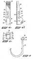
- Figs. 4a, 4b and 4c show a top view, a side view and a front view respectively of a supporting part 20 according to a second embodiment of the bracket unit according to the invention.
- the supporting part 20 has sharply projecting ribs 21, corresponding to the ribs 16 of the first embodiment shown in Fig. 3, on the top side of the supporting part 20 forming a supporting surface.
- the supporting part 20 has flanges 22 which run downwards from the top side (supporting surface) and which run parallel to each other at a distance d, and at one end each have a bore 23 for the passage of a hinge pin (not shown) which runs at right angles to the supporting part 20 and can be formed by a bolt and a nut, which can be accommodated in a polygonal recess 24 in such a way that they cannot turn.
- a bore 25 formed by a slot running in the lengthwise direction of the supporting part 20 is suitable for the passage of a bolt 6 (Fig. 1).
- the bore 25 passes through a chamber 26 which runs in the lengthwise direction of the supporting part 20 and the width of which is greater than the width of the slot 25, and which is suitable for accommodation of a nut, such as a nut 4, in such a way that it can slide and cannot turn therein.
- the chamber or nut nesting space 26 is bounded at one end by a wall 27 and at another end by a projection 28. The nut 4 can be pushed over the projection 28 into the chamber 26, in which process the projection 28 is elastically deformed and subsequent loss of the nut 4 from the chamber 26 is prevented.
- the end of the supporting part 20 at the bores 23 for a hinge pin has between the flanges 22 an insertion space 29 for a coupling part 30 at one end of a bracket part 31, the other, bottom end of which can support therein in clamping fashion a gutter (not shown).
- the coupling part 30 is of a width which is equal to the distance d between the flanges 22 of the supporting part 20 and has a bore 32 for the passage of the hinge pin after the coupling part 30 is inserted into the insertion space 29.
- arc parts 33, 34 with the hinge pin as the centre point provision is made on the inside of the flanges 22 and on the outside of the coupling part 30 for raised parts and recesses which engage with each other after the coupling part 30 has been inserted. in the insertion space 29.
- the bracket part 31 before or after the bracket unit is fastened to the roof 1, the bracket part 31 can be turned into a desired angular position and locked therein, so that the bracket unit can be used in a simple manner for roofs with different slopes. This means that relatively few different parts need to be produced and held in stock, so that the cost of this second embodiment can be relatively low.
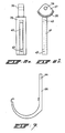
- Figs. 6 and 7 show another embodiment of the bracket part 31 shown in Fig. 5 for use with the supporting part 20 shown in Fig. 4.
- the bracket part shown in Figs. 6 and 7 comprises two sub-parts 35, 36, of which the sub-part 35 has a head part 37, like the head part 30 of the bracket part 31 of Fig. 5, with a similar arc part 38 with raised parts and recesses for engaging in the arched part 33 of the supporting part 20, and with a bore 39 for the hinge pin conveyed through the bores 23 of the supporting part 20.
- the sub-part 35 has a slot-type bore 40 which goes through a chamber 41 which is wider than the slot 40.
- the chamber 41 is bounded at one end by a wall 42 and at the other end by a projection 43.
- the chamber 41 can take a nut (not shown) in such a way that it slides and cannot turn therein. This nut can be pushed through an aperture at the projection 43 into the chamber 41, the projection 43 then being elastically deformed, following which loss of the nut from the chamber 41 is prevented.
- a top end of the sub-bracket part 36 has a bore 44 for the passage of a bolt (not shown). After the sub-bracket parts 35 and 36 are placed against each other, said bolt can be screwed via the bore 44 into the nut disposed in the chamber 41, and the sub-part 36 can be tightened with an adjustable distance relative to the head part 37 and thus relative to the corrugated sheet 1.
- a scale division 45 is provided on the outside of a flange of the supporting part 20.
- the bores 12, 15, 25 for the bolt 6 of the supporting part 3, 20 are preferably provided so close to the end of the supporting part 3, 20 where the bracket part 10, 31, 35 is inserted into the supporting part 3, 20 in order to ensure that as strong a fastening as possible of the bracket unit to the eaves section 1 can be obtained, in which the bracket unit, in particular the supporting part 3, will not sag undesirably through the weight of the gutter and the water which it contains, so that damage to the eaves section is avoided.
Landscapes
- Architecture (AREA)
- Civil Engineering (AREA)
- Structural Engineering (AREA)
- Engineering & Computer Science (AREA)
- Roof Covering Using Slabs Or Stiff Sheets (AREA)
- Investigating Or Analysing Materials By The Use Of Chemical Reactions (AREA)
- Building Awnings And Sunshades (AREA)
- Transition And Organic Metals Composition Catalysts For Addition Polymerization (AREA)
- Supports For Pipes And Cables (AREA)
- Mutual Connection Of Rods And Tubes (AREA)
- Fittings On The Vehicle Exterior For Carrying Loads, And Devices For Holding Or Mounting Articles (AREA)
- Load-Engaging Elements For Cranes (AREA)
- Rear-View Mirror Devices That Are Mounted On The Exterior Of The Vehicle (AREA)
Priority Applications (1)
| Application Number | Priority Date | Filing Date | Title |
|---|---|---|---|
| AT88202589T ATE65819T1 (de) | 1987-11-19 | 1988-11-17 | Halter zum befestigen von dachrinnen. |
Applications Claiming Priority (2)
| Application Number | Priority Date | Filing Date | Title |
|---|---|---|---|
| NL8702770A NL8702770A (nl) | 1987-11-19 | 1987-11-19 | Stelsel voor het bevestigen van een gootbevestigingsbeugel aan een dak. |
| NL8702770 | 1987-11-19 |
Publications (2)
| Publication Number | Publication Date |
|---|---|
| EP0317032A1 true EP0317032A1 (fr) | 1989-05-24 |
| EP0317032B1 EP0317032B1 (fr) | 1991-07-31 |
Family
ID=19850941
Family Applications (1)
| Application Number | Title | Priority Date | Filing Date |
|---|---|---|---|
| EP88202589A Expired - Lifetime EP0317032B1 (fr) | 1987-11-19 | 1988-11-17 | Crochet pour la fixation de gouttières |
Country Status (10)
| Country | Link |
|---|---|
| US (1) | US4940198A (fr) |
| EP (1) | EP0317032B1 (fr) |
| JP (1) | JPH01163348A (fr) |
| AT (1) | ATE65819T1 (fr) |
| AU (1) | AU605382B2 (fr) |
| CA (1) | CA1307092C (fr) |
| DE (1) | DE3864014D1 (fr) |
| DK (1) | DK167981B1 (fr) |
| NL (1) | NL8702770A (fr) |
| NZ (1) | NZ226993A (fr) |
Cited By (2)
| Publication number | Priority date | Publication date | Assignee | Title |
|---|---|---|---|---|
| GB2231897A (en) * | 1989-05-02 | 1990-11-28 | Novaview Ltd | Gutter mounting assembly |
| WO2015174831A1 (fr) * | 2014-05-14 | 2015-11-19 | Jarola Vision B.V. | Dispositif de fixation d'une gouttière à une structure de bâtiment, structure de bâtiment comprenant un tel dispositif, élément de fixation, élément de support |
Families Citing this family (5)
| Publication number | Priority date | Publication date | Assignee | Title |
|---|---|---|---|---|
| AUPR454401A0 (en) * | 2001-04-24 | 2001-05-24 | Poldmaa, Arvo | Ladderlink |
| US7418801B2 (en) * | 2005-04-08 | 2008-09-02 | James Loveless | Standing seam-mounted gutter bracket |
| DE102012224528A1 (de) * | 2012-12-28 | 2014-07-03 | Reisser Schraubentechnik Gmbh | Befestigungskalotte |
| JP6202549B1 (ja) * | 2016-06-24 | 2017-09-27 | 有限会社 広島金具製作所 | 吊り金具 |
| US12546081B2 (en) * | 2023-03-30 | 2026-02-10 | Allan P Henderson | Radial bolt corrugated pipe mold and assembly for cementitious foundations, and method for stabilization |
Citations (8)
| Publication number | Priority date | Publication date | Assignee | Title |
|---|---|---|---|---|
| DE74506C (de) * | nestler & Breitfeld in Wittigsthal i. S | Mehrtheiliges, verstellbares Dachrinneneisen | ||
| US1384856A (en) * | 1920-08-18 | 1921-07-19 | Berger Brothers Co | Gutter or eaves-trough hanger or support |
| FR1406679A (fr) | 1964-06-11 | 1965-07-23 | Marais Ets | Support réglable, destiné notamment à fixer des objets au bord de toitures |
| US3809347A (en) * | 1972-10-10 | 1974-05-07 | Aluminum Co Of America | Clip and hanger structure for buildings |
| BE880052A (nl) * | 1979-11-16 | 1980-03-17 | P V B A Scala Plastics | Middel ter bevestiging van een gootklamp aan een dakplaat. |
| DE2945503A1 (de) | 1979-11-10 | 1981-05-21 | Wilhelm Bonk | Vorrichtung zum halten von regenrinnen-schellen an gewellten dachplatten |
| US4553357A (en) * | 1984-03-08 | 1985-11-19 | Bemis Manufacturing Company | Adjustable rainwater gutter mounting arrangement |
| GB2176824A (en) | 1985-06-25 | 1987-01-07 | Hunter Int Ltd | Improvements in or relating to a guttering or pipe support system |
Family Cites Families (19)
| Publication number | Priority date | Publication date | Assignee | Title |
|---|---|---|---|---|
| DE376025C (de) * | 1923-05-22 | Paul Wienicke | Eisenduebel zur Befestigung elektrischen Leitungsmaterials | |
| US749419A (en) * | 1904-01-12 | Eaves-protector | ||
| US304425A (en) * | 1884-09-02 | Eaves-trough hanger | ||
| US948901A (en) * | 1910-02-08 | Stephen T Nakashjiam | Raves-trough hanger. | |
| US707941A (en) * | 1902-03-15 | 1902-08-26 | Howard Pope | Eaves-trough hanger. |
| US1017174A (en) * | 1909-04-26 | 1912-02-13 | Valentine Sander | Bracket and support therefor. |
| US972291A (en) * | 1909-09-14 | 1910-10-11 | Frank W Thomas | Spout-hanger. |
| US1478837A (en) * | 1923-03-07 | 1923-12-25 | Rachlin Max | Gutter hanger |
| US1554778A (en) * | 1923-04-14 | 1925-09-22 | Berger Matthew Russell | Eaves-trough shank |
| US1558385A (en) * | 1925-02-20 | 1925-10-20 | Meunier Charles | Gutter mount |
| GB672950A (en) * | 1949-07-27 | 1952-05-28 | Martin Wilesmith | Improvements in or relating to brackets for fixing eaves gutters |
| US3126038A (en) * | 1960-09-02 | 1964-03-24 | jaworski | |
| FR1322199A (fr) * | 1962-02-01 | 1963-03-29 | Support de gouttière | |
| FR1474956A (fr) * | 1966-02-09 | 1967-03-31 | Perfectionnements aux crochets pour supporter des gouttières | |
| DE2061367A1 (de) * | 1969-12-27 | 1972-06-15 | Georg Mez | Vorrichtung zum Halten von Dachrinnen |
| FR2193402A5 (fr) * | 1972-07-21 | 1974-02-15 | Theulon Paul | |
| FR2312683A1 (fr) * | 1975-05-27 | 1976-12-24 | Millardet Sa | Plaquette pour la fixation de plaques de bardage ou de couverture et son procede de fabrication |
| AU8524682A (en) * | 1981-06-11 | 1983-01-04 | J.E. Matthison-Hansen | Roof or wall covering and mounting member for a gutter bracket |
| US4676706A (en) * | 1985-05-15 | 1987-06-30 | Nifco, Inc. | Clip nut |
-
1987
- 1987-11-19 NL NL8702770A patent/NL8702770A/nl not_active Application Discontinuation
-
1988
- 1988-11-10 CA CA000582863A patent/CA1307092C/fr not_active Expired - Lifetime
- 1988-11-14 US US07/270,001 patent/US4940198A/en not_active Expired - Fee Related
- 1988-11-15 AU AU25130/88A patent/AU605382B2/en not_active Ceased
- 1988-11-16 JP JP63289931A patent/JPH01163348A/ja active Pending
- 1988-11-17 AT AT88202589T patent/ATE65819T1/de not_active IP Right Cessation
- 1988-11-17 DE DE8888202589T patent/DE3864014D1/de not_active Expired - Lifetime
- 1988-11-17 EP EP88202589A patent/EP0317032B1/fr not_active Expired - Lifetime
- 1988-11-17 NZ NZ226993A patent/NZ226993A/en unknown
- 1988-11-18 DK DK644988A patent/DK167981B1/da not_active IP Right Cessation
Patent Citations (8)
| Publication number | Priority date | Publication date | Assignee | Title |
|---|---|---|---|---|
| DE74506C (de) * | nestler & Breitfeld in Wittigsthal i. S | Mehrtheiliges, verstellbares Dachrinneneisen | ||
| US1384856A (en) * | 1920-08-18 | 1921-07-19 | Berger Brothers Co | Gutter or eaves-trough hanger or support |
| FR1406679A (fr) | 1964-06-11 | 1965-07-23 | Marais Ets | Support réglable, destiné notamment à fixer des objets au bord de toitures |
| US3809347A (en) * | 1972-10-10 | 1974-05-07 | Aluminum Co Of America | Clip and hanger structure for buildings |
| DE2945503A1 (de) | 1979-11-10 | 1981-05-21 | Wilhelm Bonk | Vorrichtung zum halten von regenrinnen-schellen an gewellten dachplatten |
| BE880052A (nl) * | 1979-11-16 | 1980-03-17 | P V B A Scala Plastics | Middel ter bevestiging van een gootklamp aan een dakplaat. |
| US4553357A (en) * | 1984-03-08 | 1985-11-19 | Bemis Manufacturing Company | Adjustable rainwater gutter mounting arrangement |
| GB2176824A (en) | 1985-06-25 | 1987-01-07 | Hunter Int Ltd | Improvements in or relating to a guttering or pipe support system |
Cited By (4)
| Publication number | Priority date | Publication date | Assignee | Title |
|---|---|---|---|---|
| GB2231897A (en) * | 1989-05-02 | 1990-11-28 | Novaview Ltd | Gutter mounting assembly |
| WO2015174831A1 (fr) * | 2014-05-14 | 2015-11-19 | Jarola Vision B.V. | Dispositif de fixation d'une gouttière à une structure de bâtiment, structure de bâtiment comprenant un tel dispositif, élément de fixation, élément de support |
| NL2012816B1 (nl) * | 2014-05-14 | 2016-03-02 | Jarola Vision B V | Inrichting voor het aan een bouwkundige constructie bevestigen van een goot, bouwkundige constructie met een dergelijke inrichting, bevestigingsorgaan, draagorgaan. |
| US10000932B2 (en) | 2014-05-14 | 2018-06-19 | Jarola Vision B.V. | Device for fixing a gutter to a building construction, building construction with such a device, fixing member, support member |
Also Published As
| Publication number | Publication date |
|---|---|
| US4940198A (en) | 1990-07-10 |
| EP0317032B1 (fr) | 1991-07-31 |
| NL8702770A (nl) | 1989-06-16 |
| CA1307092C (fr) | 1992-09-08 |
| AU605382B2 (en) | 1991-01-10 |
| NZ226993A (en) | 1992-01-29 |
| DE3864014D1 (de) | 1991-09-05 |
| JPH01163348A (ja) | 1989-06-27 |
| DK167981B1 (da) | 1994-01-10 |
| DK644988D0 (da) | 1988-11-18 |
| AU2513088A (en) | 1989-05-25 |
| DK644988A (da) | 1989-05-20 |
| ATE65819T1 (de) | 1991-08-15 |
Similar Documents
| Publication | Publication Date | Title |
|---|---|---|
| US5192059A (en) | Fascia board holder | |
| US7762042B2 (en) | Wireway quick-connect system | |
| US5111632A (en) | Expandable joist hanger | |
| US4635424A (en) | One-piece fastener for securing a lining element in a removable manner on a carrying surface | |
| SK283528B6 (sk) | Nastaviteľný nosníkový záves | |
| US5797220A (en) | Fascia-soffit combination | |
| US4940198A (en) | Bracket unit for fixing a roof gutter | |
| JPH04277389A (ja) | 取付けクランプ及びその製造方法 | |
| US4432518A (en) | Eaves trough bracket assembly | |
| EP0076096B1 (fr) | Dispositif pour la fixation d'une plaque à l'aile d'une poutre | |
| US4601451A (en) | Dual amplifier tap bracket or the like | |
| US4513557A (en) | Clip for use with runner and runner assembly including the clip | |
| US20240116450A1 (en) | Roof rack for a motor vehicle, motor vehicle, and method for producing a roof rack | |
| US6254051B1 (en) | Restraining system for water heaters | |
| EP0605988A2 (fr) | Un élément de support | |
| US6240702B1 (en) | Facia board rack | |
| GB2249604A (en) | Pipe bracket | |
| EP0249478A2 (fr) | Procédé d'assemblage pour murs et dispositif | |
| NL2015568B1 (en) | A method of mounting a solar panel. | |
| JPH04190Y2 (fr) | ||
| US12295491B2 (en) | Shelf support | |
| GB2355776A (en) | Fixing assembly for channel sections | |
| JPS6237873Y2 (fr) | ||
| JPH06307042A (ja) | 竪樋取付具 | |
| JPH0428342Y2 (fr) |
Legal Events
| Date | Code | Title | Description |
|---|---|---|---|
| PUAI | Public reference made under article 153(3) epc to a published international application that has entered the european phase |
Free format text: ORIGINAL CODE: 0009012 |
|
| AK | Designated contracting states |
Kind code of ref document: A1 Designated state(s): AT BE CH DE FR GB IT LI LU NL SE |
|
| 17P | Request for examination filed |
Effective date: 19890608 |
|
| 17Q | First examination report despatched |
Effective date: 19900420 |
|
| GRAA | (expected) grant |
Free format text: ORIGINAL CODE: 0009210 |
|
| AK | Designated contracting states |
Kind code of ref document: B1 Designated state(s): AT BE CH DE FR GB IT LI LU NL SE |
|
| REF | Corresponds to: |
Ref document number: 65819 Country of ref document: AT Date of ref document: 19910815 Kind code of ref document: T |
|
| ITF | It: translation for a ep patent filed | ||
| REF | Corresponds to: |
Ref document number: 3864014 Country of ref document: DE Date of ref document: 19910905 |
|
| ET | Fr: translation filed | ||
| PLBE | No opposition filed within time limit |
Free format text: ORIGINAL CODE: 0009261 |
|
| STAA | Information on the status of an ep patent application or granted ep patent |
Free format text: STATUS: NO OPPOSITION FILED WITHIN TIME LIMIT |
|
| 26N | No opposition filed | ||
| EPTA | Lu: last paid annual fee | ||
| EAL | Se: european patent in force in sweden |
Ref document number: 88202589.3 |
|
| PGFP | Annual fee paid to national office [announced via postgrant information from national office to epo] |
Ref country code: LU Payment date: 19961001 Year of fee payment: 9 |
|
| REG | Reference to a national code |
Ref country code: CH Ref legal event code: PUE Owner name: GERRIT JAN DE WILDE TRANSFER- JAROLA DESIGN GMBH |
|
| NLS | Nl: assignments of ep-patents |
Owner name: JAROLA DESIGN GMBH |
|
| REG | Reference to a national code |
Ref country code: GB Ref legal event code: 732E |
|
| REG | Reference to a national code |
Ref country code: FR Ref legal event code: TP |
|
| PG25 | Lapsed in a contracting state [announced via postgrant information from national office to epo] |
Ref country code: LU Free format text: LAPSE BECAUSE OF NON-PAYMENT OF DUE FEES Effective date: 19971117 |
|
| PGFP | Annual fee paid to national office [announced via postgrant information from national office to epo] |
Ref country code: FR Payment date: 19991122 Year of fee payment: 12 Ref country code: CH Payment date: 19991122 Year of fee payment: 12 |
|
| PGFP | Annual fee paid to national office [announced via postgrant information from national office to epo] |
Ref country code: AT Payment date: 19991125 Year of fee payment: 12 Ref country code: GB Payment date: 19991125 Year of fee payment: 12 |
|
| PGFP | Annual fee paid to national office [announced via postgrant information from national office to epo] |
Ref country code: SE Payment date: 19991129 Year of fee payment: 12 |
|
| PG25 | Lapsed in a contracting state [announced via postgrant information from national office to epo] |
Ref country code: AT Free format text: LAPSE BECAUSE OF NON-PAYMENT OF DUE FEES Effective date: 20001117 Ref country code: GB Free format text: LAPSE BECAUSE OF NON-PAYMENT OF DUE FEES Effective date: 20001117 |
|
| PG25 | Lapsed in a contracting state [announced via postgrant information from national office to epo] |
Ref country code: SE Free format text: THE PATENT HAS BEEN ANNULLED BY A DECISION OF A NATIONAL AUTHORITY Effective date: 20001129 |
|
| PG25 | Lapsed in a contracting state [announced via postgrant information from national office to epo] |
Ref country code: LI Free format text: LAPSE BECAUSE OF NON-PAYMENT OF DUE FEES Effective date: 20001130 Ref country code: CH Free format text: LAPSE BECAUSE OF NON-PAYMENT OF DUE FEES Effective date: 20001130 |
|
| GBPC | Gb: european patent ceased through non-payment of renewal fee |
Effective date: 20001117 |
|
| REG | Reference to a national code |
Ref country code: CH Ref legal event code: PL |
|
| EUG | Se: european patent has lapsed |
Ref document number: 88202589.3 |
|
| PG25 | Lapsed in a contracting state [announced via postgrant information from national office to epo] |
Ref country code: FR Free format text: LAPSE BECAUSE OF NON-PAYMENT OF DUE FEES Effective date: 20010731 |
|
| REG | Reference to a national code |
Ref country code: FR Ref legal event code: ST |
|
| NLS | Nl: assignments of ep-patents |
Owner name: WILDKAMP B.V. |
|
| NLS | Nl: assignments of ep-patents |
Owner name: WILDKAMP B.V. |
|
| PG25 | Lapsed in a contracting state [announced via postgrant information from national office to epo] |
Ref country code: IT Free format text: LAPSE BECAUSE OF NON-PAYMENT OF DUE FEES Effective date: 20051117 |
|
| PGFP | Annual fee paid to national office [announced via postgrant information from national office to epo] |
Ref country code: DE Payment date: 20051118 Year of fee payment: 18 |
|
| PG25 | Lapsed in a contracting state [announced via postgrant information from national office to epo] |
Ref country code: DE Free format text: LAPSE BECAUSE OF NON-PAYMENT OF DUE FEES Effective date: 20070601 |
|
| PGFP | Annual fee paid to national office [announced via postgrant information from national office to epo] |
Ref country code: NL Payment date: 20071130 Year of fee payment: 20 |
|
| PGFP | Annual fee paid to national office [announced via postgrant information from national office to epo] |
Ref country code: BE Payment date: 20071128 Year of fee payment: 20 |
|
| BE20 | Be: patent expired |
Owner name: *WILDKAMP B.V. Effective date: 20081117 |
|
| NLV7 | Nl: ceased due to reaching the maximum lifetime of a patent |
Effective date: 20081117 |
|
| PG25 | Lapsed in a contracting state [announced via postgrant information from national office to epo] |
Ref country code: NL Free format text: LAPSE BECAUSE OF EXPIRATION OF PROTECTION Effective date: 20081117 |