EP0317089A2 - Trépan de roche avec paliers à rouleaux précises - Google Patents
Trépan de roche avec paliers à rouleaux précises Download PDFInfo
- Publication number
- EP0317089A2 EP0317089A2 EP88309934A EP88309934A EP0317089A2 EP 0317089 A2 EP0317089 A2 EP 0317089A2 EP 88309934 A EP88309934 A EP 88309934A EP 88309934 A EP88309934 A EP 88309934A EP 0317089 A2 EP0317089 A2 EP 0317089A2
- Authority
- EP
- European Patent Office
- Prior art keywords
- bearing
- rock bit
- set forth
- cone
- micrometers
- Prior art date
- Legal status (The legal status is an assumption and is not a legal conclusion. Google has not performed a legal analysis and makes no representation as to the accuracy of the status listed.)
- Granted
Links
Images


Classifications
-
- E—FIXED CONSTRUCTIONS
- E21—EARTH OR ROCK DRILLING; MINING
- E21B—EARTH OR ROCK DRILLING; OBTAINING OIL, GAS, WATER, SOLUBLE OR MELTABLE MATERIALS OR A SLURRY OF MINERALS FROM WELLS
- E21B10/00—Drill bits
- E21B10/08—Roller bits
- E21B10/22—Roller bits characterised by bearing, lubrication or sealing details
-
- F—MECHANICAL ENGINEERING; LIGHTING; HEATING; WEAPONS; BLASTING
- F16—ENGINEERING ELEMENTS AND UNITS; GENERAL MEASURES FOR PRODUCING AND MAINTAINING EFFECTIVE FUNCTIONING OF MACHINES OR INSTALLATIONS; THERMAL INSULATION IN GENERAL
- F16C—SHAFTS; FLEXIBLE SHAFTS; ELEMENTS OR CRANKSHAFT MECHANISMS; ROTARY BODIES OTHER THAN GEARING ELEMENTS; BEARINGS
- F16C33/00—Parts of bearings; Special methods for making bearings or parts thereof
- F16C33/30—Parts of ball or roller bearings
-
- F—MECHANICAL ENGINEERING; LIGHTING; HEATING; WEAPONS; BLASTING
- F16—ENGINEERING ELEMENTS AND UNITS; GENERAL MEASURES FOR PRODUCING AND MAINTAINING EFFECTIVE FUNCTIONING OF MACHINES OR INSTALLATIONS; THERMAL INSULATION IN GENERAL
- F16C—SHAFTS; FLEXIBLE SHAFTS; ELEMENTS OR CRANKSHAFT MECHANISMS; ROTARY BODIES OTHER THAN GEARING ELEMENTS; BEARINGS
- F16C2352/00—Apparatus for drilling
Definitions
- This invention relates to sealed bearing rotary cone rock bits. More particularly, this invention relates to precision roller bearings for seal bearing rotary cone rock bits.
- Roller bearings for rotary cone rock bits have been in the public domain for many years. Roller bearing "air" bits are typically used in open pit mines where a multiplicity of shallow holes are formed in the earth formations. These types of roller bearing rotary cone bits usually are non-sealed bits that rely on a gaseous fluid to lubricate the bearings and to flush the bearings of debris during use of the bit in a borehole. These types of mining bits utilize cylindrical roller bearings that are loosely confined (large bearing clearances) by bearing races formed between a journal and a rotary cutter cone. These open-type bearings encourage the flushing of detritus from the bearing cage by the gaseous fluid pumped under pressure through a connecting drill string.
- Sealed bearing rotary cone rock bits that incorporate cylindrical type roller bearings are typically run in a deep well borehole with drilling fluid or "mud" to move the debris from the borehole bottom to the rig floor.
- the prior art does not teach a precision roller bearing having very close fits suitable for a rock bit.
- the bearing package of the present invention includes highly refined surface finishes that complement extremely hard roller bearing elements fabricated from special bearing metals.
- a specific lubricant is utilized having lube viscosities that are unique to the bearing combination of the instant invention.
- a sealed bearing rotary cone rock bit comprises a rock bit body having a first pin end and a second cutter end.
- the body has at least one leg that extends from the body toward the second cutter end.
- the leg forms a journal bearing adapted to support a rotary cutter cone rotatively secured thereon.
- the cone has a cylindrical cavity to accept the journal.
- a roller bearing assembly includes inner and outer races that confine a multiplicity of cylindrical bearings.
- the bearing assembly is installed into the cylindrical cavity in the cone.
- the installation method may be by pressing, shrink or expansion fit (thermal process) or slip fit.
- the bearing elements may be installed simultaneously or sequentially.
- the diametrical clearance between an outside surface of the inner race, a surface of the multiplicity of cylindrical roller bearings and an inside surface of the outer race is between plus 100 micrometers to minus 50 micrometers.
- An inside surface of the inner race has a diametrical clearance between a surface of the journal of between zero and 175 micrometers.
- An advantage then, over the prior art, is a bearing combination that provides a sealed precision roller bearing having tight fits with highly refined and hardened surface finishes in combination with lubricants having specific lube viscosities.
- FIG. 1 illustrates a typical rotary cone rock bit generally designated as 10 which consists of a rock bit body 12 pin end 14 and a cutting end, generally designated as 16.
- the cutting end comprises rotatable cutter cones 22 that are attached to a leg portion 18 near shirttail 20.
- Each of the cones 22 has, for example, a multiplicity of cutter inserts 24 retained by the cone 22.
- Drilling fluid commonly known as "mud" is directed into a plenum chamber (not shown) formed by body 12 through pin end 14. The fluid or mud is then directed from the chamber out nozzles 28.
- the leg 18 of the bit 10 defines a journal 34 cantilevered from the shirttail end 20 of leg 18.
- a spindle 36 is formed on the end of the main journal 34, the spindle acting to stabilize the rotary cone 22 mounted on the journal 34.
- the cone 22 forms a cone mouth 40 which transitions into a bearing retaining groove or race 42.
- the cone 22 is secured to the journal 34 by a multiplicity of cone retention balls 39.
- a ball race 38 is formed within the cone 22 which registers with a similar ball race 31 formed in the journal 34. Balls are inserted through a ball hole 49. When the ball races 31 and 38 are full of ball bearings 39, a ball hole plus 43 is inserted in the ball hole 49 to close out the ball race 31.
- a lubricant is supplied to the bearings through a lubricant reservoir 26 (FIG. 1) down lube hole 52 into the ball plus hole 49.
- a groove 53 is provided in the ball plus 43 to enable the lubricant to reach the bearings confined between the cone 22 and the journal 34.
- Roller bearings 44 are retained within an inner bearing race 48 and the annular bearing race 42 formed in cone 22.
- the O.D. 54 of the inner bearing race 48 is sized to tightly engage the surface 45 of roller bearing 44 thereby tightly engaging the cylindrical bearings with the race 42 formed in cone 22.
- the diametrical clearance between surface 54 and surface 42 is between plus 100 micrometers and minus 50 micrometers inch.
- the preferred range is plus or minus 25 micrometers.
- the material surface hardness of all of the bearing elements including the outer surface of the inner race 48, the roller bearings 44, and the outer race 42 formed in cone 22 is within a Rockwell C hardness range between 58 Rc and 65 RC. A preferred range for the material hardness is 60 to 62 Rockwell C.
- the surface finish of all of the bearing elements are as follows: for the inner race outer surface 54, the surface should be less than 0.8 Ra (roughness average) micrometers, the inner surface of the outer race 42 should be less than 0.8 Ra micrometers and the surface of the roller bearings should be less than 0.6 Ra micrometers. It would be desirable that the surface finish of all of the bearing elements be within 0.25 Ra micrometers one from the other.
- the preferred range of surface finish of the bearing elements are as follows: inner surface of the outer race should be less than 0.5 Ra micrometers, the outer surface of the inner race should be less than 0.4 Ra micrometers and the roller bearing should be less than 0.3 Ra micrometers.
- the clearance between the outside surface 35 of journal 34 and the inside diameter 55 of the inner race 48 is preferably 100 micrometers. A particularly preferred clearance is about 25 micrometers.
- the ends 47 of roller bearings 44 are prevented from engaging or binding against the leg hub 57 and axial surface 56 formed in cone 22 by the length of the inside bearing race 48.
- a seal is provided between the cone mouth 40 and the journal bearing 34.
- the seal 50 rides on a seal gland 41 formed in the rotary cone 22.
- the inside diameter of the seal 50 rides in a complementary seal gland 51 formed at the base of the journal 34.
- roller bearings 44 are preferably crowned along their axial length at 46 thus preventing stress risers at either end of the roller bearings which may exist if the cone 22 should become misaligned with the journal 34 or heavily loaded. By crowning the roller bearings at 46, stress risers are minimized within the bearing package. It would be equivalent to crown the O.D. of the inner bearing race and the I.D. of the outer bearing race.
- the bearing elements are preferably fabricated from a high cleanliness steel which assures uniform quality of the elements.
- the steel should be free of inclusion or contaminants.
- Typical nonmetallic inclusions in steel are: A) sulfide, B) alumina, C) silicate, and D) globular oxides.
- a "J. K.” (JERKONTORET) chart categorizes these inclusions in columns and rates the inclusions from 1 to 5; 1 being low in content and 5 is high in content.
- An acceptable J. K. rating would be a range from 1 to 3.
- the preferred J. K. rating would be 1 for the steel used to fabricate the bearing elements of the present invention.
- the lubricant, or grease, utilized to lubricate the bearings should have a lubricant viscosity of greater than 100 centipoise, a preferred lubricant would have a viscosity of 500 to 5,000 centipoise (Cp) at 100 degrees Centigrade.
- An example of a lubricant having these properties is manufactured by Dow Chemical Company of Midland, Michigan, and has a product designation of FS- 1265-10,000 with a viscosity of 840 centipoise at 100 degrees Centigrade.
- a lubricant having an acceptable viscosity range is fabricated from Sta-Lube Corporation of Compton, California, with a product designation of 38995 having a viscosity of about 100 centipoise at 100 degrees Centigrade.
- Still another example of a satisfactory lubricant is manufactured by Mobiltac of New York, New York, and is known under the designation of QQ with a viscosity of about 100 centipoise at 100 degrees Centigrade.
- the bearing misalignment between the journal 34, and the cone 22 would be minimal.
- a preferred bearing misalignment would be less than .001 radian, or less than .06 degrees, It would, however, be acceptable if there is a misalignment of up to plus or minus .15 degrees between the journal and the cone.
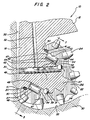
- Cone misalignment on the journal 34 happens when a rock bit typically is run in a borehole 32, as shown in FIG. 2.
- the borehole bottom 33 and the weight on the bit co-act to create an out thrust load on the cone 22 (out thrust being pressure exerted from the tip of the cone 22 towards the shirttail 20 of the leg 18).
- the loaded cone 22 tends to misalign itself with the journal 34, the load side of the journal 34, of course, being toward the bottom of the journal 34, as seen in FIG. 2. It is understandable then, that proper cone alignment with its respective journal bearing is critical and, as taught in the present invention, the tight bearing package as heretofore described, minimizes the possibility of cone misalignment.
- FIG. 3 the cross-section taken through FIG. 2, illustrates the cone 22 mounted to journal 34 with the bearings 44 confined between hardened and polished surface 42 in cone 22 and the O.D. hardened surface 54 of inner race 48.
- the preferred fit, again, between the hardened surface 54, the surface 45 of roller bearings 44, and the hardened surface 42 of cone 22 is preferably plus or minus 25 micrometers.
- the diametrical clearance between surface 56 of journal 34, and I.D. 55 of bearing race 44, is preferably about 25 micrometers.
- the ball plus hole 49 is also illustrated in this view showing the ball plus 43 and the grease passages 48 formed in the ball plus 43 to allow lubricant from the lubricant reservoir to the bearing package.
- a rotary cone 122 is mounted to a journal 134 which is cantilevered from a leg 118 adjacent shirttail portion 120.
- the leg portion 118 is shown with a lubricant reservoir system generally designated as 126.
- This type of lubricant reservoir is typical of the preferred embodiment of FIGS. 1, 2 and 3.
- the lubricant reservoir system represents the state of the art and typically includes a flexible diaphragm 130 mounted within a reservoir chamber which is held in place by a cover cap 128. The diaphragm is exposed to the exterior of the rock bit so that it may be pressure compensated between the interior cavities of the bit and the outside environment of the bit.
- Lubricant 131 is forced into a space beyond the interior of the diaphragm and is directed through lubricant passage 132 found in the leg 118 towards a ball hole plug 133.
- Groove 156 in a ball plug 155 allows the lubricant to pass into the ball race 138 in cone 122 so that the lubricant can be routed to the cone retention ball race 138, balls 139 and the roller bearing package.
- a cone mouth 140 is formed in the rotary cone 122 which leads into a bearing retention groove 141 formed in cone 122.
- a bearing package which includes an inner race 142, roller bearings 145, and outer bearing race 147, completes the bearing package.
- the outer bearing race 147 is designed to be interference fitted or press fitted within bearing grove 141, formed in cone 122.
- the diametrical clearances between the outside diameter surface 144, of inner race 142, the surface 146 of roller bearing 145 and the inner or I.D. surface 148 of outer race 147 is between a plus 100 micrometers to minus 50 micrometers. The preferred range, or clearance, is plus or minus 25 micrometers.
- roller bearings 144 may be crowned at 154 to prevent stress risers at the cylindrical ends of each of the roller bearings, thus accommodating for slight misalignments between the cone 122 an the journal 134.
- the roller bearings are prevented from binding on their ends by the length of the inner and outer bearing races 142 and 147.
- the bearing retainer ring 150 is preferably pressed within the annular bearing retainer groove 151 positioned within the cone mouth 140 of cone 122.
- the annular bearing retainer ring has formed on its inside diameter a seal gland 153 to support a resilient O-ring 152 placed between the seal gland 153, and a complementary gland formed at the base of the journal bearing 134.
- the annular bearing retaining ring is preferably metallurgically bonded to the cone 122 at the intersection of the O.D. of the ring and the annular groove 151. It would be equivalent, of course, to thread the O.D. of the bearing retainer 150 (not shown). The threaded ring would then be secured within complementary threads formed in the cone 122 (not shown).
- the clearance between the surface 135 of journal 134, and the I.D. 143 of inner bearing race 142, should be about 100 micrometers.
- roller bearings 44 would then be confined within surface 45 formed by the cone 22 and surface 35 formed by journal 34 without departing from the intent of the present invention.
Landscapes
- Engineering & Computer Science (AREA)
- General Engineering & Computer Science (AREA)
- Mechanical Engineering (AREA)
- Mining & Mineral Resources (AREA)
- Life Sciences & Earth Sciences (AREA)
- Geology (AREA)
- Fluid Mechanics (AREA)
- Environmental & Geological Engineering (AREA)
- Physics & Mathematics (AREA)
- General Life Sciences & Earth Sciences (AREA)
- Geochemistry & Mineralogy (AREA)
- Rolling Contact Bearings (AREA)
- Earth Drilling (AREA)
Applications Claiming Priority (2)
| Application Number | Priority Date | Filing Date | Title |
|---|---|---|---|
| US122156 | 1987-11-18 | ||
| US07/122,156 US4793719A (en) | 1987-11-18 | 1987-11-18 | Precision roller bearing rock bits |
Publications (3)
| Publication Number | Publication Date |
|---|---|
| EP0317089A2 true EP0317089A2 (fr) | 1989-05-24 |
| EP0317089A3 EP0317089A3 (en) | 1990-01-31 |
| EP0317089B1 EP0317089B1 (fr) | 1992-09-30 |
Family
ID=22401035
Family Applications (1)
| Application Number | Title | Priority Date | Filing Date |
|---|---|---|---|
| EP88309934A Expired - Lifetime EP0317089B1 (fr) | 1987-11-18 | 1988-10-21 | Trépan de roche avec paliers à rouleaux précises |
Country Status (4)
| Country | Link |
|---|---|
| US (1) | US4793719A (fr) |
| EP (1) | EP0317089B1 (fr) |
| DE (1) | DE3875074T2 (fr) |
| NO (1) | NO885102L (fr) |
Families Citing this family (22)
| Publication number | Priority date | Publication date | Assignee | Title |
|---|---|---|---|---|
| SE8801233L (sv) * | 1988-04-05 | 1989-10-06 | Sandvik Ab | Rullborrkrona |
| US5161898A (en) * | 1991-07-05 | 1992-11-10 | Camco International Inc. | Aluminide coated bearing elements for roller cutter drill bits |
| US6254275B1 (en) | 1995-12-19 | 2001-07-03 | Smith International, Inc. | Sealed bearing drill bit with dual-seal configuration and fluid-cleaning capability |
| US6033117A (en) * | 1995-12-19 | 2000-03-07 | Smith International, Inc. | Sealed bearing drill bit with dual-seal configuration |
| US6264367B1 (en) | 1995-12-19 | 2001-07-24 | Smith International, Inc. | Dual-seal drill bit with fluid cleaning capability |
| US6116357A (en) * | 1996-09-09 | 2000-09-12 | Smith International, Inc. | Rock drill bit with back-reaming protection |
| US6619412B2 (en) | 1996-09-09 | 2003-09-16 | Smith International, Inc. | Protected lubricant reservoir for sealed earth boring drill bit |
| CA2240023C (fr) * | 1997-07-01 | 2007-02-13 | Smith International, Inc. | Reservoir de lubrifiant protege pour trepan de forage a roulements etanches |
| ZA99430B (en) | 1998-01-23 | 1999-07-21 | Smith International | Hardfacing rock bit cones for erosion protection. |
| US6386302B1 (en) * | 1999-09-09 | 2002-05-14 | Smith International, Inc. | Polycrystaline diamond compact insert reaming tool |
| FI123802B (fi) * | 2004-09-03 | 2013-10-31 | Sandvik Mining & Constr Oy | Rikotuslaite ja menetelmä rikotuslaitteen työkalun voitelemiseksi |
| EP1717507B1 (fr) * | 2005-04-27 | 2010-07-14 | Caterpillar Inc. | Dispositif de lubrification pour outil hydraulique ou pneumatique |
| US20080011519A1 (en) * | 2006-07-17 | 2008-01-17 | Baker Hughes Incorporated | Cemented tungsten carbide rock bit cone |
| RU2332552C2 (ru) * | 2006-12-11 | 2008-08-27 | Государственное образовательное учреждение высшего профессионального образования Самарский государственный технический университет | Опора бурового шарошечного долота |
| RU2364699C1 (ru) * | 2008-03-06 | 2009-08-20 | Николай Митрофанович Панин | Буровое шарошечное долото |
| US20090229886A1 (en) * | 2008-03-11 | 2009-09-17 | Baker Hughes Incorporated | Non-Grease Type Bearing Lubricant |
| US20090308662A1 (en) * | 2008-06-11 | 2009-12-17 | Lyons Nicholas J | Method of selectively adapting material properties across a rock bit cone |
| WO2012024503A1 (fr) | 2010-08-19 | 2012-02-23 | Caterpillar Inc. | Système de lubrification pour outil de concassage |
| US9010493B2 (en) | 2012-03-13 | 2015-04-21 | Caterpillar Inc. | Lubrication arrangement |
| CN102828693B (zh) * | 2012-09-25 | 2015-03-04 | 西南石油大学 | 一种滚滑浮动套轴承的牙轮钻头 |
| US9217341B2 (en) | 2013-08-15 | 2015-12-22 | Caterpillar Inc. | Lubrication system for tool |
| CN105089508A (zh) * | 2014-05-05 | 2015-11-25 | 成都百施特金刚石钻头有限公司 | 一种旋转钻井钻头及制造方法 |
Family Cites Families (17)
| Publication number | Priority date | Publication date | Assignee | Title |
|---|---|---|---|---|
| US2030442A (en) * | 1933-10-28 | 1936-02-11 | Hughes Tool Co | Roller bearing bit |
| US2644671A (en) * | 1947-03-04 | 1953-07-07 | Martell D Ingram | Rock drilling bit |
| US2983560A (en) * | 1953-03-04 | 1961-05-09 | Roulements A Aiguilles Soc Sa | Antifriction bearing |
| US3193028A (en) * | 1962-09-26 | 1965-07-06 | Exxon Production Research Co | Rotary drill bit |
| US3178241A (en) * | 1963-03-18 | 1965-04-13 | Space Technology And Res Corp | Lubricationless high-temperature bearing |
| US3797900A (en) * | 1972-08-16 | 1974-03-19 | Chrysler Corp | Bearing assembly |
| US3923348A (en) * | 1974-03-13 | 1975-12-02 | Reed Tool Co | Friction bearing |
| US3990525A (en) * | 1975-02-27 | 1976-11-09 | Dresser Industries, Inc. | Sealing system for a rotary rock bit |
| US4136748A (en) * | 1977-11-07 | 1979-01-30 | The Timken Company | Roller-type rock bit and bearing arrangement therefor |
| DE2755591C2 (de) * | 1977-12-14 | 1985-11-07 | SKF GmbH, 8720 Schweinfurt | Rollenmeißel mit kegelig ausgebildeten Schneidrollen |
| DE2823698C2 (de) * | 1978-05-31 | 1981-09-17 | Skf Kugellagerfabriken Gmbh, 8720 Schweinfurt | Rollenmeißel mit einem Einfülloch für Lagerrollen |
| DE7828401U1 (de) * | 1978-09-23 | 1979-01-04 | Sandvik Gmbh, 4000 Duesseldorf | Rollenmeissel mit mehreren schneidrollen |
| US4263976A (en) * | 1979-05-29 | 1981-04-28 | Sandvik Ab, Fack & Aktiebolaget Skf | Rotary drill bit with rotary cutters |
| DE8007104U1 (de) * | 1980-03-15 | 1980-06-12 | Skf Kugellagerfabriken Gmbh, 8720 Schweinfurt | Rollenmeissel mit kegeligen schneidrollen |
| US4359113A (en) * | 1980-09-08 | 1982-11-16 | Hughes Tool Company | Earth boring bit with extended gage |
| US4386668A (en) * | 1980-09-19 | 1983-06-07 | Hughes Tool Company | Sealed lubricated and air cooled rock bit bearing |
| US4428687A (en) * | 1981-05-11 | 1984-01-31 | Hughes Tool Company | Floating seal for earth boring bit |
-
1987
- 1987-11-18 US US07/122,156 patent/US4793719A/en not_active Expired - Lifetime
-
1988
- 1988-10-21 EP EP88309934A patent/EP0317089B1/fr not_active Expired - Lifetime
- 1988-10-21 DE DE8888309934T patent/DE3875074T2/de not_active Expired - Fee Related
- 1988-11-16 NO NO88885102A patent/NO885102L/no unknown
Also Published As
| Publication number | Publication date |
|---|---|
| NO885102D0 (no) | 1988-11-16 |
| EP0317089A3 (en) | 1990-01-31 |
| US4793719A (en) | 1988-12-27 |
| DE3875074D1 (de) | 1992-11-05 |
| DE3875074T2 (de) | 1993-02-25 |
| EP0317089B1 (fr) | 1992-09-30 |
| NO885102L (no) | 1989-05-19 |
Similar Documents
| Publication | Publication Date | Title |
|---|---|---|
| US4793719A (en) | Precision roller bearing rock bits | |
| EP0479927B1 (fr) | Composant de colonne de forage | |
| US5715898A (en) | Stabiliser for a downhole apparatus | |
| US4572306A (en) | Journal bushing drill bit construction | |
| US7621346B1 (en) | Hydrostatic bearing | |
| US4899838A (en) | Earth boring bit with convergent cutter bearing | |
| US4903786A (en) | Earth boring bit with improved two piece bearing and seal assembly | |
| US4923020A (en) | Rock bit with rigid face seals and recessed energizers | |
| US5381868A (en) | Sealed bearing roller reamer | |
| US4381824A (en) | Drill bit lubrication system | |
| US2104819A (en) | Roller boring drill | |
| US4671368A (en) | Earth boring bit with shear compression seal | |
| US4061376A (en) | Rock bit bearing structure | |
| US4209890A (en) | Method of making a rotary rock bit with seal recess washer | |
| CA2312151C (fr) | Systeme de retention de taillant tricone | |
| US4344658A (en) | Earth boring drill bit with snap ring cutter retention | |
| US3307645A (en) | Reverse bearing bit | |
| US4261426A (en) | Reamer stabilizer | |
| US4514098A (en) | Wound wire bearing | |
| EP0415519B1 (fr) | Système d'étanchéité double pour trépan de forage rotatif | |
| US4491428A (en) | Earth boring drill bit with snap ring cutter retention | |
| US4330158A (en) | Rotary rock bit with improved thrust flange | |
| EP0678150B1 (fr) | Aleseur ameliore a rouleaux rotatifs | |
| US4161343A (en) | Cone retainer for a rotary rock bit | |
| US4236764A (en) | Earth boring drill bit with snap ring cutter retention |
Legal Events
| Date | Code | Title | Description |
|---|---|---|---|
| PUAI | Public reference made under article 153(3) epc to a published international application that has entered the european phase |
Free format text: ORIGINAL CODE: 0009012 |
|
| AK | Designated contracting states |
Kind code of ref document: A2 Designated state(s): DE FR GB IT NL |
|
| PUAL | Search report despatched |
Free format text: ORIGINAL CODE: 0009013 |
|
| AK | Designated contracting states |
Kind code of ref document: A3 Designated state(s): DE FR GB IT NL |
|
| 17P | Request for examination filed |
Effective date: 19900331 |
|
| 17Q | First examination report despatched |
Effective date: 19910404 |
|
| GRAA | (expected) grant |
Free format text: ORIGINAL CODE: 0009210 |
|
| AK | Designated contracting states |
Kind code of ref document: B1 Designated state(s): DE FR GB IT NL |
|
| ITF | It: translation for a ep patent filed | ||
| PGFP | Annual fee paid to national office [announced via postgrant information from national office to epo] |
Ref country code: NL Payment date: 19921031 Year of fee payment: 5 |
|
| REF | Corresponds to: |
Ref document number: 3875074 Country of ref document: DE Date of ref document: 19921105 |
|
| ET | Fr: translation filed | ||
| PGFP | Annual fee paid to national office [announced via postgrant information from national office to epo] |
Ref country code: FR Payment date: 19930215 Year of fee payment: 5 |
|
| PGFP | Annual fee paid to national office [announced via postgrant information from national office to epo] |
Ref country code: DE Payment date: 19930225 Year of fee payment: 5 |
|
| PLBE | No opposition filed within time limit |
Free format text: ORIGINAL CODE: 0009261 |
|
| STAA | Information on the status of an ep patent application or granted ep patent |
Free format text: STATUS: NO OPPOSITION FILED WITHIN TIME LIMIT |
|
| 26N | No opposition filed | ||
| PG25 | Lapsed in a contracting state [announced via postgrant information from national office to epo] |
Ref country code: NL Effective date: 19940501 |
|
| NLV4 | Nl: lapsed or anulled due to non-payment of the annual fee | ||
| PG25 | Lapsed in a contracting state [announced via postgrant information from national office to epo] |
Ref country code: FR Effective date: 19940630 |
|
| PG25 | Lapsed in a contracting state [announced via postgrant information from national office to epo] |
Ref country code: DE Effective date: 19940701 |
|
| REG | Reference to a national code |
Ref country code: FR Ref legal event code: ST |
|
| REG | Reference to a national code |
Ref country code: GB Ref legal event code: IF02 |
|
| PG25 | Lapsed in a contracting state [announced via postgrant information from national office to epo] |
Ref country code: IT Free format text: LAPSE BECAUSE OF NON-PAYMENT OF DUE FEES;WARNING: LAPSES OF ITALIAN PATENTS WITH EFFECTIVE DATE BEFORE 2007 MAY HAVE OCCURRED AT ANY TIME BEFORE 2007. THE CORRECT EFFECTIVE DATE MAY BE DIFFERENT FROM THE ONE RECORDED. Effective date: 20051021 |
|
| PGFP | Annual fee paid to national office [announced via postgrant information from national office to epo] |
Ref country code: GB Payment date: 20071029 Year of fee payment: 20 |
|
| REG | Reference to a national code |
Ref country code: GB Ref legal event code: PE20 Expiry date: 20081020 |
|
| PG25 | Lapsed in a contracting state [announced via postgrant information from national office to epo] |
Ref country code: GB Free format text: LAPSE BECAUSE OF EXPIRATION OF PROTECTION Effective date: 20081020 |