EP0317171A2 - Integrales Dünnschicht-Injektionssystem für einen thermischen Tintenspritzdruckkopf und Arbeitsmethoden - Google Patents
Integrales Dünnschicht-Injektionssystem für einen thermischen Tintenspritzdruckkopf und Arbeitsmethoden Download PDFInfo
- Publication number
- EP0317171A2 EP0317171A2 EP88310572A EP88310572A EP0317171A2 EP 0317171 A2 EP0317171 A2 EP 0317171A2 EP 88310572 A EP88310572 A EP 88310572A EP 88310572 A EP88310572 A EP 88310572A EP 0317171 A2 EP0317171 A2 EP 0317171A2
- Authority
- EP
- European Patent Office
- Prior art keywords
- ink
- ink jet
- jet printhead
- printhead
- flow path
- Prior art date
- Legal status (The legal status is an assumption and is not a legal conclusion. Google has not performed a legal analysis and makes no representation as to the accuracy of the status listed.)
- Withdrawn
Links
Images

Classifications
-
- B—PERFORMING OPERATIONS; TRANSPORTING
- B41—PRINTING; LINING MACHINES; TYPEWRITERS; STAMPS
- B41J—TYPEWRITERS; SELECTIVE PRINTING MECHANISMS, i.e. MECHANISMS PRINTING OTHERWISE THAN FROM A FORME; CORRECTION OF TYPOGRAPHICAL ERRORS
- B41J2/00—Typewriters or selective printing mechanisms characterised by the printing or marking process for which they are designed
- B41J2/005—Typewriters or selective printing mechanisms characterised by the printing or marking process for which they are designed characterised by bringing liquid or particles selectively into contact with a printing material
- B41J2/01—Ink jet
- B41J2/135—Nozzles
- B41J2/14—Structure thereof only for on-demand ink jet heads
- B41J2/14016—Structure of bubble jet print heads
- B41J2/14088—Structure of heating means
- B41J2/14112—Resistive element
- B41J2/14129—Layer structure
-
- B—PERFORMING OPERATIONS; TRANSPORTING
- B41—PRINTING; LINING MACHINES; TYPEWRITERS; STAMPS
- B41J—TYPEWRITERS; SELECTIVE PRINTING MECHANISMS, i.e. MECHANISMS PRINTING OTHERWISE THAN FROM A FORME; CORRECTION OF TYPOGRAPHICAL ERRORS
- B41J2/00—Typewriters or selective printing mechanisms characterised by the printing or marking process for which they are designed
- B41J2/005—Typewriters or selective printing mechanisms characterised by the printing or marking process for which they are designed characterised by bringing liquid or particles selectively into contact with a printing material
- B41J2/01—Ink jet
- B41J2/135—Nozzles
- B41J2/14—Structure thereof only for on-demand ink jet heads
- B41J2/14016—Structure of bubble jet print heads
- B41J2/14032—Structure of the pressure chamber
- B41J2/14056—Plural heating elements per ink chamber
-
- B—PERFORMING OPERATIONS; TRANSPORTING
- B41—PRINTING; LINING MACHINES; TYPEWRITERS; STAMPS
- B41J—TYPEWRITERS; SELECTIVE PRINTING MECHANISMS, i.e. MECHANISMS PRINTING OTHERWISE THAN FROM A FORME; CORRECTION OF TYPOGRAPHICAL ERRORS
- B41J2/00—Typewriters or selective printing mechanisms characterised by the printing or marking process for which they are designed
- B41J2/005—Typewriters or selective printing mechanisms characterised by the printing or marking process for which they are designed characterised by bringing liquid or particles selectively into contact with a printing material
- B41J2/01—Ink jet
- B41J2/135—Nozzles
- B41J2/14—Structure thereof only for on-demand ink jet heads
- B41J2002/14387—Front shooter
Definitions
- This invention relates generally to thermal ink jet (TIJ) printing and more particularly to such printing using multiple heater resistors to control ink drop ejection from a TIJ orifice plate
- TFR thin film resistor
- a general object of this invention is to provide a new and improved thermal ink jet printhead and method of operation which extends the upper limit of the ink ejection operational frequency, while simultaneously increasing the variability and control of drop volume of ink ejected from the printhead.
- Another object of this invention is to provide a new and improved thermal ink jet printhead of the type described which is operative to reduce hydrodynamic back pressure and cavitation wear on certain heater resistors of the printhead structure.
- Another object is to provide a new and improved thermal ink jet printhead of the type described which is operative to eject variable drop volumes of ink, thereby resulting in variable dot sizes.
- Another object is to provide a new and improved thermal ink jet printhead of the type described which allows ink to be preheated to a preselected controlled temperature in order to exert control on the viscosity of the ink. Such operation maintains a desired and controlled viscosity level in the ink.
- Another object is to provide a new and improved thermal ink jet printhead of the type described which is operative to impart controlled quantities of thermal energy to the ink, which in turn allows subsequent ejection of a drop or drops of ink with shorter duration and lower energy pulses.
- a further object of this invention is to provide a new and improved thermal ink jet printhead of the type described which may be operated to limit underdamped oscillatory fluid waves through dynamic loading, thereby resulting in an enhanced operating frequency and improved harmonic control.
- an ink jet printhead assembly which includes means providing an ink flow path between an ink supply and an ink ejection orifice, and an ink injection chamber and a drop ejection chamber are located in series between the source of ink supply and an ink ejection orifice.
- the ink injection chamber contains at least one ink injection heater resistor and the drop ejection chamber contains at least one drop ejection heater resistor.
- Electrical pulse control means are connected to both the ink injection heater resistor and to the drop ejection heater resistor for sequentially pulsing these resistors to thereby reduce hydrodynamic back pressure from the drop ejection chamber. This switching action also reduces the impact of cavitational forces from the ink ejection orifice and normal to the major surface of the drop ejection heater resistor.
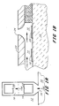
- a supporting substrate 10 of either a semiconductor or a glass material is prepared to receive a barrier layer 12 thereon which defines the ink reservoir geometry of the printhead, including an ink injection chamber 14 and a drop ejection chamber 16.
- the ink injection chamber 14 is provided with an ink injection heater resistor 18, whereas the drop ejection chamber 16 is provided with a drop ejection heater resistor 20.
- An outer or top orifice plate 22 is provided as shown in Figure 1B and has an output orifice 24 which is either precisely aligned with the drop ejection heater resistor 20 or is offset with respect thereto by a predetermined dimension or dimensions.
- the heater resistors 18 and 20 are represented only schematically and would, in their actual construction, typically include an underlying passivation and heat control layer and a covering protection layer such as SiC or Si3N4 or both in addition to the lead-in conductors. All of these materials have been omitted in Figs. 1A and 1B for sake of brevity and illustrating the basic concept underlying the present invention.
- the ink injection heater resistor 18 and the drop ejection heater resistor 20 are connected by way of conductive trace material (not shown in this figure) which has been patterned to form lead-in conductors for the heater resistors.
- lead-in conductors are shown in Figures 3, 4 and 5 below and provide an electrical connection for conducting controlled current pulses to both the ink injection heater resistor 18 and the drop ejection heater resistor 20 during a thermal ink jet printing operation.
- the utilization of the ink injection heater resistor 18 in this manner serves to decrease the time in which it takes for ink entering the opening 26 to reach the drop ejection heater resistor 20. In this manner, the operational frequency range of the thermal ink jet printhead is extended.
- the above operation further serves to reduce hydrodynamic back pressure and cavitation wear on the heater resistors of the printhead structures, and it also preheats the ink flowing to the drop ejection chamber.
- the latter feature serves to control the temperature of the ink, and thereby controls its viscosity.
- the present invention further permits the modulation of ejected drop volume by phasing the heating pulses to the injection heater resistor 18 and the ejection heater resistor 20.
- the injection heater 18 is pulsed before the ejection heater 20, a disturbance of the fluid meniscus in the orifice 24 is produced.
- the fluid in the orifice region 24 will have volume and kinetic energy controllable by the timing delay between the activation of the injection heater 18 and the ejection heater 20.
- the volume and kinetic energy of the fluid when the ejection heater 20 is subsequently activated provides a different initial condition to the drop ejection mechanism compared to the quiescent state where the ejection heater 20 is activated alone. This mechanism allows for the modulation of the drop volume both above and below the nominal value obtained when the ejection heater 20 is activated alone.
- the printhead structure shown in isometric view is also shown without the conductive trace leads connected to heater resistors 18 and 20 and without the top orifice plate applied to the barrier layer 12.
- This figure is useful to show the general position of the two heater resistors 18 and 20 with respect to the ink flow path into the ink injection chamber 14 and by way of convergent barrier wall sections 28 and 30 which define the width dimension of the ink flow input port 26.
- the convergent contours of the barrier walls 28 and 30 are utilized to constrict ink flow into the ink injection chamber and thereby provide the necessary hydraulic tuning for optimizing the ink ejection efficiency of the thermal ink jet printhead.
- this hydraulic tuning and related fluidic control techniques reference may be made to copending European application serial number 88310139.6 of Kenneth Trueba et al and assigned to the present assignee.
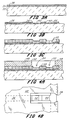
- a silicon or glass substrate 32 is typically used as the thin film resistor substrate starting material and is treated in a conventional manner, such as by etching and polishing, to receive a surface layer 34 of resistive heater material, such as tantalum-aluminum.
- the resistive heater layer 34 is in turn adapted to receive a layer 36 of conductive trace material, such as aluminum or gold.
- the conductive trace layer 36 is configured using conventional photolithographic masking and etching processes to provide openings 38 and 40 therein as shown in Figure 3B.
- the openings 38 and 40 in the conductive trace layer 36 in turn define the length and width dimensions of a pair of heater resistors 42 and 44 which, of course, correspond to the schematically represented heater resistors 20 and 18 in the schematic and abbreviated views of Figures 1 and 2.
- a resistive heater barrier layer 46 is provided as shown in Figure 3C to insulate the underlying heater resistors 42 and 44 and the conductive trace material 36 in Figure 3B from ink corrosion and cavitation wear.
- This surface barrier layer 46 will typically consist of a combination of an initial thin layer of silicon nitride on top of which an outer layer of silicon carbide is formed using known nitride and carbide deposition techniques.
- the Si3N4 portion of the barrier layer 46 provides a good materials match with the underlying layers of TaA1 and metal, and the SiC outer portion of the barrier layer 46 provides a highly inert outer protective film to insulate the underlying materials against ink corrosion.
- a second or ink reservoir-defining barrier layer 48 is provided in the geometry shown in Figures 4A and 4B.
- the second or outer surface barrier layer 48 is masked and etched using conventional state-of-the-art photolithographic masking and etching techniques in order to form an opening 50 which now defines the length and width dimensions of the ink injection chamber and the drop ejection chamber.
- These chambers are located approximately at the reference numerals 52 and 54 and above the ink injection and drop ejection resistors 44 and 42, respectively.
- top orifice plate 56 having a convergent orifice therein which terminates at an output opening 58 and includes a converging and smoothly contoured surface 60.
- the output orifice opening 58 is aligned with respect to the drop ejection heater resistor 42, and in some applications a small offset between orifice plate opening 58 and heater resistor 42 may be preferred.
- ink traversing the flow path indicated at the arrow 62 will enter the ink injection chamber 52 above the ink injection resistor 44 and then proceed to flow into the drop ejection chamber 54 atop the drop ejection heater resistor 42 in a manner previously described.
- the outer barrier layer 48 may be constructed of well known polymer materials, such as materials known as RISTON or VACREL and sold by the Dupont Co. of Wilmington, Delaware.
- the outer surface barrier layer 48 may be a metal such as nickel and electroformed using processes such as those described in the above identified Hewlett-Packard Journal.
- the orifice plate 56 may be manufactured from metal or plastic using known fabrication techniques, and when a metal such as nickel is used for forming both the barrier layer 48 and the orifice plate 56, then one may prefer to employ the electroforming processes disclosed in allowed copending European application No.87900407.5 of Chor S. Chan et al entitled "Barrier Layer and Orifice Plate For Thermal Ink Jet Printhead Assembly", assigned to the present assignee and incorporated herein by reference.
- PECVD plasma enhanced chemical vapor deposition
- LPCVD liquid phase chemical vapor deposition
Landscapes
- Particle Formation And Scattering Control In Inkjet Printers (AREA)
Applications Claiming Priority (2)
| Application Number | Priority Date | Filing Date | Title |
|---|---|---|---|
| US12030087A | 1987-11-13 | 1987-11-13 | |
| US120300 | 1993-09-13 |
Publications (2)
| Publication Number | Publication Date |
|---|---|
| EP0317171A2 true EP0317171A2 (de) | 1989-05-24 |
| EP0317171A3 EP0317171A3 (de) | 1990-07-18 |
Family
ID=22389436
Family Applications (1)
| Application Number | Title | Priority Date | Filing Date |
|---|---|---|---|
| EP88310572A Withdrawn EP0317171A3 (de) | 1987-11-13 | 1988-11-10 | Integrales Dünnschicht-Injektionssystem für einen thermischen Tintenspritzdruckkopf und Arbeitsmethoden |
Country Status (2)
| Country | Link |
|---|---|
| EP (1) | EP0317171A3 (de) |
| JP (1) | JPH01156075A (de) |
Cited By (34)
| Publication number | Priority date | Publication date | Assignee | Title |
|---|---|---|---|---|
| EP0507134A3 (en) * | 1991-04-02 | 1992-11-19 | Hewlett-Packard Company | An ink jet print head having two cured photoimaged barrier layers |
| EP0465071A3 (en) * | 1990-06-24 | 1992-12-23 | Lexmark International, Inc. | Ink jet print head |
| EP0492638A3 (en) * | 1990-12-28 | 1993-01-20 | Canon Kabushiki Kaisha | Recording system with automatic sheet supplying apparatus |
| EP0786343A3 (de) * | 1996-01-23 | 1998-05-20 | Hewlett-Packard Company | Thermischer Tintenstrahldrucker und Ansteuerungsverfahren |
| EP0863005A1 (de) * | 1997-03-04 | 1998-09-09 | Hewlett-Packard Company | Struktur zum Bewirken einer Haftung zwischen dem Substrat und der Tintensperre in einem Tintenstrahldruckkopf |
| WO1999037486A1 (en) * | 1998-01-23 | 1999-07-29 | Kim Chang Jin | Apparatus and method for using bubble as virtual valve in microinjector to eject fluid |
| EP0899109A3 (de) * | 1997-08-29 | 1999-09-15 | Hewlett-Packard Company | Druckkopf mit reduzierten Abmessungen für einen Tintenstrahldrucker |
| EP0955166A1 (de) * | 1998-04-29 | 1999-11-10 | Hewlett-Packard Company | Dünnschicht-Tintenstrahldruckkopf |
| EP0894625A3 (de) * | 1997-07-31 | 2000-08-23 | Canon Kabushiki Kaisha | Verfahren und Vorrichtng zum Ausstossen von Flüssigkeit |
| US6209991B1 (en) | 1997-03-04 | 2001-04-03 | Hewlett-Packard Company | Transition metal carbide films for applications in ink jet printheads |
| EP1149705A1 (de) | 2000-04-26 | 2001-10-31 | Samsung Electronics Co., Ltd. | Mit Bläschen angetriebener Tintenstrahldruckkopf, dazugehöriges Herstellungsverfahren, und Tintenausstossverfahren |
| EP1172212A2 (de) | 2000-07-11 | 2002-01-16 | Samsung Electronics Co., Ltd. | Tintenstrahldruckkopf des mit Bläschen angetrieben Typs |
| EP1174268A1 (de) | 2000-07-18 | 2002-01-23 | Samsung Electronics Co., Ltd. | Mit Bläschen angetriebener Tintenstrahldruckkopf und dazugehöriges Hertsellungsverfahren |
| EP1221374A2 (de) | 2001-01-08 | 2002-07-10 | Samsung Electronics Co., Ltd. | Hemisphärische Tintenstrahldruckkopffarbkammer und Herstellungsverfahren |
| EP1195253A4 (de) * | 1999-07-12 | 2002-10-09 | Copyer Co | Vorrichtung zur bilderzeugung durch ein tintenstrahldrucksystem |
| WO2002081224A1 (en) * | 2001-04-03 | 2002-10-17 | Benq Corporation | Microinjector having drive circuit and method for making the same |
| US6471338B2 (en) | 2001-01-19 | 2002-10-29 | Benq Corporation | Microinjector head having driver circuitry thereon and method for making the same |
| US6561625B2 (en) | 2000-12-15 | 2003-05-13 | Samsung Electronics Co., Ltd. | Bubble-jet type ink-jet printhead and manufacturing method thereof |
| US6652077B2 (en) | 2001-10-29 | 2003-11-25 | Samsung Electronics Co., Ltd. | High-density ink-jet printhead having a multi-arrayed structure |
| US6676244B2 (en) | 2001-08-09 | 2004-01-13 | Samsung Electronics Co., Ltd. | Bubble-jet type inkjet printhead |
| US6676844B2 (en) | 2000-12-18 | 2004-01-13 | Samsung Electronics Co. Ltd. | Method for manufacturing ink-jet printhead having hemispherical ink chamber |
| US6726308B2 (en) * | 2000-07-24 | 2004-04-27 | Samsung Electronics Co., Ltd. | Bubble-jet type ink-jet printhead |
| EP1447222A1 (de) * | 2003-01-15 | 2004-08-18 | Samsung Electronics Co., Ltd. | Tintenstrahldruckkopf |
| US6789880B2 (en) | 2001-06-28 | 2004-09-14 | Benq Corporation | Microinjector for jetting droplets of different sizes |
| KR100460244B1 (ko) * | 2001-02-23 | 2004-12-08 | 캐논 가부시끼가이샤 | 잉크 제트 헤드, 그 제조 방법 및 잉크 제트 기록 장치 |
| US6902257B2 (en) * | 2001-11-08 | 2005-06-07 | Benq Corporation | Fluid injection head structure and method for manufacturing the same |
| US7011392B2 (en) * | 2002-01-24 | 2006-03-14 | Industrial Technology Research Institute | Integrated inkjet print head with rapid ink refill mechanism and off-shooter heater |
| US7195341B2 (en) | 2004-09-30 | 2007-03-27 | Lexmark International, Inc. | Power and ground buss layout for reduced substrate size |
| US7275308B2 (en) | 2001-10-25 | 2007-10-02 | Samsung Electronics Co., Ltd. | Method for manufacturing a monolithic ink-jet printhead |
| CN100346969C (zh) * | 2003-06-20 | 2007-11-07 | 明基电通股份有限公司 | 流体喷射装置 |
| EP2598334A4 (de) * | 2010-05-21 | 2018-02-21 | Hewlett-Packard Development Company, L.P. | Flüssigkeitsausstossanordnung mit umwälzpumpe |
| CN110682683A (zh) * | 2016-01-08 | 2020-01-14 | 佳能株式会社 | 液体喷射头、液体喷射设备和供应液体的方法 |
| US11260668B2 (en) | 2010-05-21 | 2022-03-01 | Hewlett-Packard Development Company, L.P. | Fluid ejection device including recirculation system |
| US11642891B2 (en) | 2016-01-08 | 2023-05-09 | Canon Kabushiki Kaisha | Liquid ejection head, liquid ejection apparatus, and method of supplying liquid |
Families Citing this family (2)
| Publication number | Priority date | Publication date | Assignee | Title |
|---|---|---|---|---|
| JP2836749B2 (ja) * | 1989-05-09 | 1998-12-14 | 株式会社リコー | 液体噴射記録ヘッド |
| US8757783B2 (en) * | 2010-07-28 | 2014-06-24 | Hewlett-Packard Development Company, L.P. | Fluid ejection assembly with circulation pump |
Family Cites Families (3)
| Publication number | Priority date | Publication date | Assignee | Title |
|---|---|---|---|---|
| JPS55132259A (en) * | 1979-04-02 | 1980-10-14 | Canon Inc | Liquid jet recording method |
| US4646110A (en) * | 1982-12-29 | 1987-02-24 | Canon Kabushiki Kaisha | Liquid injection recording apparatus |
| JPS62240558A (ja) * | 1986-04-14 | 1987-10-21 | Canon Inc | 液体噴射記録ヘツド |
-
1988
- 1988-11-10 EP EP88310572A patent/EP0317171A3/de not_active Withdrawn
- 1988-11-11 JP JP28561488A patent/JPH01156075A/ja active Pending
Cited By (56)
| Publication number | Priority date | Publication date | Assignee | Title |
|---|---|---|---|---|
| EP0465071A3 (en) * | 1990-06-24 | 1992-12-23 | Lexmark International, Inc. | Ink jet print head |
| EP0492638A3 (en) * | 1990-12-28 | 1993-01-20 | Canon Kabushiki Kaisha | Recording system with automatic sheet supplying apparatus |
| US6249295B1 (en) | 1990-12-28 | 2001-06-19 | Canon Kabushiki Kaisha | Recording apparatus with self-standing recording unit and sheet supplying apparatus |
| EP0507134A3 (en) * | 1991-04-02 | 1992-11-19 | Hewlett-Packard Company | An ink jet print head having two cured photoimaged barrier layers |
| EP0786343A3 (de) * | 1996-01-23 | 1998-05-20 | Hewlett-Packard Company | Thermischer Tintenstrahldrucker und Ansteuerungsverfahren |
| US6209991B1 (en) | 1997-03-04 | 2001-04-03 | Hewlett-Packard Company | Transition metal carbide films for applications in ink jet printheads |
| EP0863005A1 (de) * | 1997-03-04 | 1998-09-09 | Hewlett-Packard Company | Struktur zum Bewirken einer Haftung zwischen dem Substrat und der Tintensperre in einem Tintenstrahldruckkopf |
| US6155674A (en) * | 1997-03-04 | 2000-12-05 | Hewlett-Packard Company | Structure to effect adhesion between substrate and ink barrier in ink jet printhead |
| EP1125746A1 (de) * | 1997-03-04 | 2001-08-22 | Hewlett-Packard Company | Struktur zum Bewirken einer Haftung zwischen dem Substrat und der Tintensperre in einem Tintenstrahldruckkopf |
| EP0894625A3 (de) * | 1997-07-31 | 2000-08-23 | Canon Kabushiki Kaisha | Verfahren und Vorrichtng zum Ausstossen von Flüssigkeit |
| US6375309B1 (en) | 1997-07-31 | 2002-04-23 | Canon Kabushiki Kaisha | Liquid discharge apparatus and method for sequentially driving multiple electrothermal converting members |
| US6146915A (en) * | 1997-08-29 | 2000-11-14 | Hewlett-Packard Company | Reduced size printhead for an inkjet printer |
| EP0899109A3 (de) * | 1997-08-29 | 1999-09-15 | Hewlett-Packard Company | Druckkopf mit reduzierten Abmessungen für einen Tintenstrahldrucker |
| AU752431B2 (en) * | 1998-01-23 | 2002-09-19 | Benq Corporation | Apparatus and method for using bubble as virtual valve in microinjector to eject fluid |
| US6102530A (en) * | 1998-01-23 | 2000-08-15 | Kim; Chang-Jin | Apparatus and method for using bubble as virtual valve in microinjector to eject fluid |
| WO1999037486A1 (en) * | 1998-01-23 | 1999-07-29 | Kim Chang Jin | Apparatus and method for using bubble as virtual valve in microinjector to eject fluid |
| KR100563360B1 (ko) * | 1998-01-23 | 2006-03-22 | 에이서 커뮤니케이션즈 앤드 멀티미디어 인코포레이티드 | 마이크로인젝터 내에서 버블을 가상 밸브로서 이용하여 유체를 분출하는 장치 및 방법 |
| CN1299905C (zh) * | 1998-01-23 | 2007-02-14 | 明碁电通股份有限公司 | 在喷射液体的微型喷射器中用气泡作为一个实际上的阀的装置和方法 |
| US6126277A (en) * | 1998-04-29 | 2000-10-03 | Hewlett-Packard Company | Non-kogating, low turn on energy thin film structure for very low drop volume thermal ink jet pens |
| EP0955166A1 (de) * | 1998-04-29 | 1999-11-10 | Hewlett-Packard Company | Dünnschicht-Tintenstrahldruckkopf |
| EP1195253A4 (de) * | 1999-07-12 | 2002-10-09 | Copyer Co | Vorrichtung zur bilderzeugung durch ein tintenstrahldrucksystem |
| US6499832B2 (en) | 2000-04-26 | 2002-12-31 | Samsung Electronics Co., Ltd. | Bubble-jet type ink-jet printhead capable of preventing a backflow of ink |
| US6685846B2 (en) | 2000-04-26 | 2004-02-03 | Samsung Electronics Co., Ltd. | Bubble-jet type ink-jet printhead, manufacturing method thereof, and ink ejection method |
| EP1149705A1 (de) | 2000-04-26 | 2001-10-31 | Samsung Electronics Co., Ltd. | Mit Bläschen angetriebener Tintenstrahldruckkopf, dazugehöriges Herstellungsverfahren, und Tintenausstossverfahren |
| EP1172212A2 (de) | 2000-07-11 | 2002-01-16 | Samsung Electronics Co., Ltd. | Tintenstrahldruckkopf des mit Bläschen angetrieben Typs |
| EP1174268A1 (de) | 2000-07-18 | 2002-01-23 | Samsung Electronics Co., Ltd. | Mit Bläschen angetriebener Tintenstrahldruckkopf und dazugehöriges Hertsellungsverfahren |
| US6749762B2 (en) | 2000-07-18 | 2004-06-15 | Samsung Electronics Co., Ltd. | Bubble-jet type ink-jet printhead and manufacturing method thereof |
| US6533399B2 (en) | 2000-07-18 | 2003-03-18 | Samsung Electronics Co., Ltd. | Bubble-jet type ink-jet printhead and manufacturing method thereof |
| US7263773B2 (en) | 2000-07-24 | 2007-09-04 | Samsung Electronics Co., Ltd. | Method of manufacturing a bubble-jet type ink-jet printhead |
| US6726308B2 (en) * | 2000-07-24 | 2004-04-27 | Samsung Electronics Co., Ltd. | Bubble-jet type ink-jet printhead |
| US6561625B2 (en) | 2000-12-15 | 2003-05-13 | Samsung Electronics Co., Ltd. | Bubble-jet type ink-jet printhead and manufacturing method thereof |
| US6868605B2 (en) | 2000-12-15 | 2005-03-22 | Samsung Electronics Co., Ltd. | Method of manufacturing a bubble-jet type ink-jet printhead |
| US6676844B2 (en) | 2000-12-18 | 2004-01-13 | Samsung Electronics Co. Ltd. | Method for manufacturing ink-jet printhead having hemispherical ink chamber |
| EP1221374A2 (de) | 2001-01-08 | 2002-07-10 | Samsung Electronics Co., Ltd. | Hemisphärische Tintenstrahldruckkopffarbkammer und Herstellungsverfahren |
| US6585355B2 (en) | 2001-01-08 | 2003-07-01 | Samsung Electronics Co., Ltd. | Ink-jet printhead having hemispherical ink chamber and method for manufacturing the same |
| US6478408B2 (en) | 2001-01-08 | 2002-11-12 | Samsung Electronics Co., Ltd. | Ink-jet printhead having hemispherical ink chamber and method for manufacturing the same |
| US6471338B2 (en) | 2001-01-19 | 2002-10-29 | Benq Corporation | Microinjector head having driver circuitry thereon and method for making the same |
| KR100460244B1 (ko) * | 2001-02-23 | 2004-12-08 | 캐논 가부시끼가이샤 | 잉크 제트 헤드, 그 제조 방법 및 잉크 제트 기록 장치 |
| WO2002081224A1 (en) * | 2001-04-03 | 2002-10-17 | Benq Corporation | Microinjector having drive circuit and method for making the same |
| US6789880B2 (en) | 2001-06-28 | 2004-09-14 | Benq Corporation | Microinjector for jetting droplets of different sizes |
| US6676244B2 (en) | 2001-08-09 | 2004-01-13 | Samsung Electronics Co., Ltd. | Bubble-jet type inkjet printhead |
| US7275308B2 (en) | 2001-10-25 | 2007-10-02 | Samsung Electronics Co., Ltd. | Method for manufacturing a monolithic ink-jet printhead |
| US6652077B2 (en) | 2001-10-29 | 2003-11-25 | Samsung Electronics Co., Ltd. | High-density ink-jet printhead having a multi-arrayed structure |
| US6902257B2 (en) * | 2001-11-08 | 2005-06-07 | Benq Corporation | Fluid injection head structure and method for manufacturing the same |
| US7011392B2 (en) * | 2002-01-24 | 2006-03-14 | Industrial Technology Research Institute | Integrated inkjet print head with rapid ink refill mechanism and off-shooter heater |
| US7252776B2 (en) | 2002-01-24 | 2007-08-07 | Industrial Technology Research Institute | Method for fabricating a thermal bubble inkjet print head with rapid ink refill mechanism and off-shooter heater |
| US7101024B2 (en) | 2003-01-15 | 2006-09-05 | Samsung Electronics Co., Ltd. | Ink-jet printhead |
| EP1447222A1 (de) * | 2003-01-15 | 2004-08-18 | Samsung Electronics Co., Ltd. | Tintenstrahldruckkopf |
| CN100346969C (zh) * | 2003-06-20 | 2007-11-07 | 明基电通股份有限公司 | 流体喷射装置 |
| US7195341B2 (en) | 2004-09-30 | 2007-03-27 | Lexmark International, Inc. | Power and ground buss layout for reduced substrate size |
| US7344227B2 (en) | 2004-09-30 | 2008-03-18 | Lexmark International, Inc. | Power and ground buss layout for reduced substrate size |
| EP2598334A4 (de) * | 2010-05-21 | 2018-02-21 | Hewlett-Packard Development Company, L.P. | Flüssigkeitsausstossanordnung mit umwälzpumpe |
| US11260668B2 (en) | 2010-05-21 | 2022-03-01 | Hewlett-Packard Development Company, L.P. | Fluid ejection device including recirculation system |
| CN110682683A (zh) * | 2016-01-08 | 2020-01-14 | 佳能株式会社 | 液体喷射头、液体喷射设备和供应液体的方法 |
| US11642891B2 (en) | 2016-01-08 | 2023-05-09 | Canon Kabushiki Kaisha | Liquid ejection head, liquid ejection apparatus, and method of supplying liquid |
| US12319064B2 (en) | 2016-01-08 | 2025-06-03 | Canon Kabushiki Kaisha | Liquid ejection head, liquid ejection apparatus, and method of supplying liquid |
Also Published As
| Publication number | Publication date |
|---|---|
| JPH01156075A (ja) | 1989-06-19 |
| EP0317171A3 (de) | 1990-07-18 |
Similar Documents
| Publication | Publication Date | Title |
|---|---|---|
| EP0317171A2 (de) | Integrales Dünnschicht-Injektionssystem für einen thermischen Tintenspritzdruckkopf und Arbeitsmethoden | |
| EP0244214B1 (de) | Thermischer Tintenstrahldruckkopf | |
| US6070969A (en) | Thermal inkjet printhead having a preferred nucleation site | |
| KR100563360B1 (ko) | 마이크로인젝터 내에서 버블을 가상 밸브로서 이용하여 유체를 분출하는 장치 및 방법 | |
| US4490728A (en) | Thermal ink jet printer | |
| EP1563999B1 (de) | Tropfenerzeugungsdruckkopf mit hoher Auflösung | |
| JP3917677B2 (ja) | インクジェットプリントヘッド | |
| US5912685A (en) | Reduced crosstalk inkjet printer printhead | |
| KR100554807B1 (ko) | 유체액적을분사하기위한프린트헤드및유체액적형성방법 | |
| US5371527A (en) | Orificeless printhead for an ink jet printer | |
| EP0390346B1 (de) | Wärmeanwendende Tintenstrahlvorrichtung | |
| US6276775B1 (en) | Variable drop mass inkjet drop generator | |
| US4922265A (en) | Ink jet printhead with self-aligned orifice plate and method of manufacture | |
| CA2048277C (en) | Control of energy to thermal inkjet heating elements | |
| US5760804A (en) | Ink-jet printing head for a liquid-jet printing device operating on the heat converter principle and process for making it | |
| US6443564B1 (en) | Asymmetric fluidic techniques for ink-jet printheads | |
| US7263773B2 (en) | Method of manufacturing a bubble-jet type ink-jet printhead | |
| JPH06238904A (ja) | インクジェットプリントヘッドにおけるインク充填スロットの形成方法 | |
| JPH06996A (ja) | 液滴吐出器 | |
| US6460961B2 (en) | Heater of bubble-jet type ink-jet printhead for gray scale printing and manufacturing method thereof | |
| US5208606A (en) | Directionality of thermal ink jet transducers by front face metalization | |
| WO2001072429A2 (en) | Apparatus for using bubbles as virtual valve in microinjector to eject fluid | |
| EP2313276B1 (de) | Druckkopf mit isolierter heizvorrichtung | |
| EP0750991B1 (de) | Tintenstrahlaufzeichnungskopf und Tintenstrahlaufzeichnungsapparat | |
| US6142611A (en) | Oxide island structure for flexible inkjet printhead and method of manufacture thereof |
Legal Events
| Date | Code | Title | Description |
|---|---|---|---|
| PUAI | Public reference made under article 153(3) epc to a published international application that has entered the european phase |
Free format text: ORIGINAL CODE: 0009012 |
|
| AK | Designated contracting states |
Kind code of ref document: A2 Designated state(s): DE FR GB IT |
|
| PUAL | Search report despatched |
Free format text: ORIGINAL CODE: 0009013 |
|
| AK | Designated contracting states |
Kind code of ref document: A3 Designated state(s): DE FR GB IT |
|
| STAA | Information on the status of an ep patent application or granted ep patent |
Free format text: STATUS: THE APPLICATION IS DEEMED TO BE WITHDRAWN |
|
| 18D | Application deemed to be withdrawn |
Effective date: 19910119 |