EP0317248A2 - Procédé et dispositif pour serrer et déserrer, à faible moment de torsion, des écrous de boulons traversant un corps statorique - Google Patents
Procédé et dispositif pour serrer et déserrer, à faible moment de torsion, des écrous de boulons traversant un corps statorique Download PDFInfo
- Publication number
- EP0317248A2 EP0317248A2 EP88310746A EP88310746A EP0317248A2 EP 0317248 A2 EP0317248 A2 EP 0317248A2 EP 88310746 A EP88310746 A EP 88310746A EP 88310746 A EP88310746 A EP 88310746A EP 0317248 A2 EP0317248 A2 EP 0317248A2
- Authority
- EP
- European Patent Office
- Prior art keywords
- bolt
- nut
- thrust
- compression
- set screws
- Prior art date
- Legal status (The legal status is an assumption and is not a legal conclusion. Google has not performed a legal analysis and makes no representation as to the accuracy of the status listed.)
- Withdrawn
Links
Images

Classifications
-
- F—MECHANICAL ENGINEERING; LIGHTING; HEATING; WEAPONS; BLASTING
- F16—ENGINEERING ELEMENTS AND UNITS; GENERAL MEASURES FOR PRODUCING AND MAINTAINING EFFECTIVE FUNCTIONING OF MACHINES OR INSTALLATIONS; THERMAL INSULATION IN GENERAL
- F16B—DEVICES FOR FASTENING OR SECURING CONSTRUCTIONAL ELEMENTS OR MACHINE PARTS TOGETHER, e.g. NAILS, BOLTS, CIRCLIPS, CLAMPS, CLIPS OR WEDGES; JOINTS OR JOINTING
- F16B15/00—Nails; Staples
-
- H—ELECTRICITY
- H02—GENERATION; CONVERSION OR DISTRIBUTION OF ELECTRIC POWER
- H02K—DYNAMO-ELECTRIC MACHINES
- H02K15/00—Processes or apparatus specially adapted for manufacturing, assembling, maintaining or repairing of dynamo-electric machines
- H02K15/02—Processes or apparatus specially adapted for manufacturing, assembling, maintaining or repairing of dynamo-electric machines of stator or rotor bodies
- H02K15/021—Magnetic cores
-
- Y—GENERAL TAGGING OF NEW TECHNOLOGICAL DEVELOPMENTS; GENERAL TAGGING OF CROSS-SECTIONAL TECHNOLOGIES SPANNING OVER SEVERAL SECTIONS OF THE IPC; TECHNICAL SUBJECTS COVERED BY FORMER USPC CROSS-REFERENCE ART COLLECTIONS [XRACs] AND DIGESTS
- Y10—TECHNICAL SUBJECTS COVERED BY FORMER USPC
- Y10T—TECHNICAL SUBJECTS COVERED BY FORMER US CLASSIFICATION
- Y10T29/00—Metal working
- Y10T29/49—Method of mechanical manufacture
- Y10T29/49002—Electrical device making
- Y10T29/49009—Dynamoelectric machine
Definitions
- This invention relates to electric power generators, and, more particularly, to an improved assembly for retensioning through-bolts used to compress stator core punchings.
- the generator comprises a rotor journaled in a stator, the rotor containing copper coil windings which carry a direct current for producing a magnetic flux.
- the power source spins the rotor at high speeds, causing the magnetic flux to sweep across copper coil windings in the stator and generate an electric current.
- the generator stator comprises a cylindrical core having longitudinal slots along an inner surface, each slot containing a pair of top and bottom half turn coils.
- the top and bottom half turn coils emerge from the longitudinal slots at each end of the stator core and turn in order to connect with other half turn coils, thus forming a coil winding.
- the plurality of emerging end coils at each end of a stator core form an end winding basket.
- This basket arrangement of individual end coils must be consolidated into a unified structure in order to restrain radial and tangential coil movements which result from large electro-magnetic forces, thermal expansion and coil vibration.
- Bracing assemblies are commonly used to secure end coils and reduce coil wear which results from coil movement during generator operation.
- end coil bracing assemblies In order to provide sufficient mass and stiffness for reducing steady state coil vibration and other sources of coil movement, the end coil bracing assemblies must be relatively large. As a result there are very limited clearances about the end winding basket and portions of the stator core are not readily accessible for maintenance and repair.
- bracing assemblies which further reduce coil movement in the end winding baskets of an electrical generator have used bracing systems in which a non-metallic segmented ring is positioned against upper surfaces of top end coils and a non-metallic cone shaped support ring is positioned against lower surfaces of bottom end coils to provide a continuous rigid support about the end winding basket.
- These rings are formed of a relatively rigid, baked fiber glass/epoxy resin composite. In order to minimize coil movement, such support rings may be substantially larger than other bracing systems which have been used to secure end coils against movement.
- the cylindrical stator core which may exceed 762 cm in length, is formed from a plurality of stacked punchings.
- a series of longitudinal through-bolts extending through the entire length of stacked punchings are used to compress the punchings between a pair of end plates and consolidate them into a unified structure. This arrangement minimizes vibration and stator core deformation which result from the large electromagnetic forces present during generator operation.
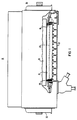
- FIG. 1 illustrates, in partial cutaway, a generator 11 have a rotor 13 journaled within a stator core 15 within a support frame 17.
- the stator punchings 19 are sandwiched between a pair of insulation washers 21,22 and a pair of steel compression plates 23, 24 to distribute the compression forces.
- Through-bolts 25 having first and second threaded ends 27 and 29 are positioned to extend outward through the punchings 19 and the compression plates 23,24 on both the exciter end 33 and the turbine end 35 of the generator 11.
- Procedures for stressing a stator core through-bolt 25 during generator assembly have involved first installing insulation washers 21,22, compression plates 23,24, insulation bushings 45,46, washers 43,44 and tensioning nuts 41,42 on the first and second bolt ends 27 and 29. The nuts are hand tightened against the stacked punchings 19 and the steel compression plates 23,24. Next, a tensioning nut 41,42 on one bolt end, e.g. the first end 27, is locked to the through-bolt 25 by deforming the bolt threads in order to prevent the nut from backing out. Then a hydraulic tensioning tool (not illustrated) is threaded onto the other bolt end, e.g. the second end 29, over the other tensioning nut 42.
- the through-bolt 25 is stressed with the tensioning tool to provide a desired compressive force against the stacked punchings 19. This creates a gap between the adjacent tensioning nut 42 and compression plate 24.
- the nut 42 is then threaded onto the bolt 25 to remove the gap and is locked in place by deforming the bolt threads.
- the tensioning tool is released so that the locked tension nuts 41,42 hold the through-bolt 25 in a stressed position to retain a compressive force against the stacked punchings 19.
- half turn coils are placed int he longitudinal slots of the stator core and the end coils are interconnected to form a coil winding. With the winding in place, a bracing assembly is installed at each end of the turbine to secure the end coils into a unified structure.
- tensioning nuts have been locked in place by deforming the nut threads as well as the bolt threads during factory assembly in order to prevent backing out of the nuts 41,42.
- deformities in the nut threads and bolt threads adjacent the nuts must be machined in order to thread the nuts 41,42 inward for retensioning. Therefore, it has become a common practice to not deform the nut threads and to only deform the bolt threads up to one revolution in front of the nuts 41,42.
- This technique alleviates having to machine the nut and bolt threads when retensioning the through-bolts 25.
- a disadvantage of the technique is that it allows the nuts 41,42 to back out up to one revolution of threading when they are installed.
- the present invention comprises a through-bolt extending through stacked punchings of a stator core, a tensioning nut threaded onto a first through-bolt end and a thrust nut having a central threaded bore for positioning on a second bolt end.
- the thrust nut comprises a plurality of set screws positioned about the central bore and extending through the nut parallel to the central bore. The set screws are positionable against a thrust washer in order to retension the through-bolt.
- the method for retensioning a stator core through-bolt with the thrust nut involves torquing the individual set screws against the thrust washer until a desired level of through-bolt tension is attained.
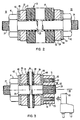
- a low-torque thrust nut 51 having a central threaded bore 53 positioned about a central axis 55 of a stator core through bolt 25 for tensioning and retensioning the through-bolt 25.
- the tensioned through-bolt 25 extends through the stator core 15 (partially illustrated in Fig. 3) to compress a plurality of stacked punchings 19.
- the punchings 19 are sandwiched between first and second insulation washers 21 and first and second steel compression plates 23.
- First and second threaded ends 27 and 29 both the bolt 25 extend outward through the insulation washers 21,22 and compression plates 23,24 for bolt tensioning.
- a tensioning nut 41 of the above described type utilized in the prior art, is threaded onto the first end 27 of the through-bolt 25 for stressing the bolt 25 with a tension tool (not illustrated).
- a first insulated bushing 45 and a steel washer 43 are interposed between the tensioning nut 41 and the first compression plate 23.
- the thrust nut 51 is threaded on the second end 29 of the through-bolt 25 against a steel thrust washer 44.
- a second insulated bushing 46 is positioned between the second compression plate and the second washer 44.
- the thrust nut 51 includes a plurality of set screws 57, each positioned in a partially threaded set screw bore 59 for torquing against the second steel washer 44. Torquing the set screws stresses the through-bolt without requiring that the thrust nut be turned.
- the set screw bores 59 are disposed about the central bore 53, each bore 59 extending the entire length of the thrust nut 51.
- An inner end 61 of each set screw bore 59, facing the thrust washer 44, is threaded for passing a one of the set screws 57.
- Each threaded bore 59 may include a nylon or other type plastic insert (not illustrated) to prevent the set screws from backing out after they are torqued in place.
- An outer end 63 of each set screw 57 is adapted to receive a hex-wrench 65 for torquing the set screws 57 against the second washer 44.
- Each set screw bore 59 includes an unthreaded outer end 67 which is diametrically smaller than the second set screw end 63.
- the set screws 57 are positionable in the bores 59 only through the inner bore ends 61 so that the set screws 57 are prevented from backing out through the second bore ends 67 after the thrust nut 51 is installed on the through-bolt 25. This assures confinement of the set screws 57 when the thrust nut 51 is subjected to large electromagnetic forces experienced during generator operation.
- the method for tensioning the through-bolt 25 with the low-torque thrust nut during factory assembly is similar to the method for tensioning the through-bolt 25 with tensioning nuts 41,42 positioned at each end of the bolt 25.
- a tension tool (not illustrated) is threaded onto the first end 27 of the through-bolt 25 to stress the bolt 25.
- the tensioning nut 41 is then threaded inward and locked in place in order to remove any gaps between the tensioning nut 41 and the near end of stator core 15.
- the tension tool is removed so that the resulting through-bolt tension forces between the tension nut 41 and the low-torque thrust nut 51 compress the stator core punchings 19.
- the through-bolt 25 may be retensioned with the low-torque thrust nut 51 according to a novel method.
- the through-bolt 25 is retensioned by merely torquing down the set screws 57 against the thrust washer 44 until a desired level of through-bolt tension is attained.
- the nylon inserts help to prevent the set screws 57 from backing out after being torqued in place. This method of retensioning the through-bolt 25 does not require turning of either the tension nut 41 or the novel low-torque thrust nut 51.
- the nuts 51 and 41 may be permanently locked in place during factory installation by deforming the threads on the nuts 51 and 41 as well as on the first and second bolt ends 27 and 29. With the low-torque thrust nut 51, this permanent nut locking prevents losses in compression forces on the punchings 19 during the installation process and does not affect through-bolt retensioning.
- a further advantage of the present method for retensioning the through-bolts 25 is that it overcomes many of the problems of limited access prevalent in many electric generators by allowing retensioning to be accomplished by tightening the relatively small, e.g. 1.27 cm, set screws with a hand tool such as a hex-wrench 65.
Landscapes
- Engineering & Computer Science (AREA)
- Manufacturing & Machinery (AREA)
- Power Engineering (AREA)
- General Engineering & Computer Science (AREA)
- Mechanical Engineering (AREA)
- Iron Core Of Rotating Electric Machines (AREA)
- Manufacture Of Motors, Generators (AREA)
Applications Claiming Priority (2)
| Application Number | Priority Date | Filing Date | Title |
|---|---|---|---|
| US07/121,815 US4810919A (en) | 1987-11-16 | 1987-11-16 | Low-torque nuts for stator core through-bolts |
| US121815 | 1987-11-16 |
Publications (2)
| Publication Number | Publication Date |
|---|---|
| EP0317248A2 true EP0317248A2 (fr) | 1989-05-24 |
| EP0317248A3 EP0317248A3 (fr) | 1989-10-18 |
Family
ID=22398978
Family Applications (1)
| Application Number | Title | Priority Date | Filing Date |
|---|---|---|---|
| EP88310746A Withdrawn EP0317248A3 (fr) | 1987-11-16 | 1988-11-14 | Procédé et dispositif pour serrer et déserrer, à faible moment de torsion, des écrous de boulons traversant un corps statorique |
Country Status (6)
| Country | Link |
|---|---|
| US (1) | US4810919A (fr) |
| EP (1) | EP0317248A3 (fr) |
| JP (1) | JPH01160334A (fr) |
| KR (1) | KR890008466A (fr) |
| CN (1) | CN1033911A (fr) |
| YU (1) | YU207188A (fr) |
Cited By (4)
| Publication number | Priority date | Publication date | Assignee | Title |
|---|---|---|---|---|
| WO1999019970A1 (fr) * | 1997-10-13 | 1999-04-22 | Abb Ab | Stator et procede de production d'un stator |
| US6891303B2 (en) | 1996-05-29 | 2005-05-10 | Abb Ab | High voltage AC machine winding with grounded neutral circuit |
| EP2453561A3 (fr) * | 2010-11-12 | 2017-12-13 | General Electric Company | Procédé et appareil de compression d'un paquet de tôles pour machine dynamo-électrique |
| DE102019110951B4 (de) | 2019-04-29 | 2024-05-02 | Dr. Ing. H.C. F. Porsche Aktiengesellschaft | Verfahren und Vorrichtung zur Montage und/oder Demontage eines Permanentmagnet-Motors |
Families Citing this family (50)
| Publication number | Priority date | Publication date | Assignee | Title |
|---|---|---|---|---|
| US5069587A (en) * | 1990-06-13 | 1991-12-03 | Dresser Industries, Inc. | Securing nut apparatus |
| US5083889A (en) * | 1990-10-04 | 1992-01-28 | Steinbock Rolf H | Structure for preventing escape of jack bolts in apparatus to mechanically stress a bolt-type fastener |
| US5066882A (en) * | 1991-01-07 | 1991-11-19 | Westinghouse Electric Corp. | Stator core assembly |
| JP2000511338A (ja) | 1996-05-29 | 2000-08-29 | アセア ブラウン ボヴェリ エービー | 高圧巻線用導体および前記導体を含む巻線を備える回転電気機械 |
| CZ385998A3 (cs) | 1996-05-29 | 1999-06-16 | Abb Ab | Izolovaný vodič pro velmi vysoké napětí a způsob jeho výroby |
| SE9602079D0 (sv) | 1996-05-29 | 1996-05-29 | Asea Brown Boveri | Roterande elektriska maskiner med magnetkrets för hög spänning och ett förfarande för tillverkning av densamma |
| US6972505B1 (en) | 1996-05-29 | 2005-12-06 | Abb | Rotating electrical machine having high-voltage stator winding and elongated support devices supporting the winding and method for manufacturing the same |
| AU718706B2 (en) | 1996-05-29 | 2000-04-20 | Abb Ab | A DC transformer/reactor |
| SE510192C2 (sv) | 1996-05-29 | 1999-04-26 | Asea Brown Boveri | Förfarande och kopplingsarrangemang för att minska problem med tredjetonsströmmar som kan uppstå vid generator - och motordrift av växelströmsmaskiner kopplade till trefas distributions- eller transmissionsnät |
| SE515843C2 (sv) | 1996-11-04 | 2001-10-15 | Abb Ab | Axiell kylning av rotor |
| SE510422C2 (sv) | 1996-11-04 | 1999-05-25 | Asea Brown Boveri | Magnetplåtkärna för elektriska maskiner |
| SE512917C2 (sv) | 1996-11-04 | 2000-06-05 | Abb Ab | Förfarande, anordning och kabelförare för lindning av en elektrisk maskin |
| SE509072C2 (sv) | 1996-11-04 | 1998-11-30 | Asea Brown Boveri | Anod, anodiseringsprocess, anodiserad tråd och användning av sådan tråd i en elektrisk anordning |
| SE9704427D0 (sv) | 1997-02-03 | 1997-11-28 | Asea Brown Boveri | Infästningsanordning för elektriska roterande maskiner |
| SE9704422D0 (sv) | 1997-02-03 | 1997-11-28 | Asea Brown Boveri | Ändplatta |
| SE508544C2 (sv) | 1997-02-03 | 1998-10-12 | Asea Brown Boveri | Förfarande och anordning för montering av en stator -lindning bestående av en kabel. |
| SE9704412D0 (sv) | 1997-02-03 | 1997-11-28 | Asea Brown Boveri | Krafttransformator/reaktor |
| SE508543C2 (sv) | 1997-02-03 | 1998-10-12 | Asea Brown Boveri | Hasplingsanordning |
| SE510452C2 (sv) | 1997-02-03 | 1999-05-25 | Asea Brown Boveri | Transformator med spänningsregleringsorgan |
| SE9704421D0 (sv) | 1997-02-03 | 1997-11-28 | Asea Brown Boveri | Seriekompensering av elektrisk växelströmsmaskin |
| SE9704431D0 (sv) | 1997-02-03 | 1997-11-28 | Asea Brown Boveri | Effektreglering av synkronmaskin |
| SE9704423D0 (sv) | 1997-02-03 | 1997-11-28 | Asea Brown Boveri | Roterande elektrisk maskin med spolstöd |
| SE9704413D0 (sv) | 1997-02-03 | 1997-11-28 | Asea Brown Boveri | Krafttransformator/reaktor |
| SE513083C2 (sv) | 1997-09-30 | 2000-07-03 | Abb Ab | Synkronkompensatoranläggning jämte användning av dylik samt förfarande för faskompensation i ett högspänt kraftfält |
| US5934853A (en) * | 1997-10-24 | 1999-08-10 | Junkers; John K. | Nut and device for tightening provided with the same |
| SE513555C2 (sv) | 1997-11-27 | 2000-10-02 | Abb Ab | Förfarande för applicering av ett rörorgan i ett utrymme i en roterande elektrisk maskin och roterande elektrisk maskin enligt förfarandet |
| BR9815420A (pt) | 1997-11-28 | 2001-07-17 | Abb Ab | Método e dispositivo para controlar o fluxo magnético com um enrolamento auxiliar em uma máquina rotativa de alta voltagem de corrente alternada |
| GB2331853A (en) | 1997-11-28 | 1999-06-02 | Asea Brown Boveri | Transformer |
| GB2331867A (en) | 1997-11-28 | 1999-06-02 | Asea Brown Boveri | Power cable termination |
| GB2331858A (en) | 1997-11-28 | 1999-06-02 | Asea Brown Boveri | A wind power plant |
| US6801421B1 (en) | 1998-09-29 | 2004-10-05 | Abb Ab | Switchable flux control for high power static electromagnetic devices |
| US6067000A (en) * | 1999-01-21 | 2000-05-23 | Siemens Automotive Corporation | Electromagnetic actuator upper spring assembly |
| US6104116A (en) * | 1999-04-16 | 2000-08-15 | Siemens Westinghouse Power Corporation | Generator stator keybar compliant clamp and current shunt |
| SE516002C2 (sv) | 2000-03-01 | 2001-11-05 | Abb Ab | Roterande elektrisk maskin samt förfarande för framställning av en statorlindning |
| US6885273B2 (en) | 2000-03-30 | 2005-04-26 | Abb Ab | Induction devices with distributed air gaps |
| SE516442C2 (sv) | 2000-04-28 | 2002-01-15 | Abb Ab | Stationär induktionsmaskin och kabel därför |
| US6346760B1 (en) * | 2000-12-14 | 2002-02-12 | General Electric Company | Axial bolt-in cage stator frame assembly and method for assembling a stator |
| US6685406B2 (en) * | 2001-10-30 | 2004-02-03 | Riverhawk Company | Perforated nut tensioning system |
| CN101317006A (zh) * | 2005-11-24 | 2008-12-03 | 维斯塔斯风力系统有限公司 | 风轮机塔架、用于装配风轮机塔架的连接装置及其方法 |
| US7696661B2 (en) * | 2006-04-12 | 2010-04-13 | Gm Global Technology Operations, Inc. | Stator for an electric motor and assembly method |
| ES2386519T3 (es) * | 2008-11-27 | 2012-08-22 | Vestas Wind Systems A/S | Torre para una turbina eólica y método para montar la torre |
| US8138654B2 (en) * | 2009-05-19 | 2012-03-20 | General Electric Company | System and method for generator stator mounting |
| US8154168B2 (en) * | 2009-11-04 | 2012-04-10 | Hiwin Mikrosystem Corp. | Fixing enhancement mechanism for large iron core |
| EP2893615B8 (fr) * | 2012-08-31 | 2019-07-17 | Lappeenranta-Lahti University of Technology LUT | Machine électrique |
| WO2014190064A1 (fr) * | 2013-05-21 | 2014-11-27 | Davis John D | Tête d'écrou et/ou boulon de vérin à vis à double actionnement ayant une rondelle de charge verrouillée et un empilement de rondelles de blocage à actionnement par vérin à vis |
| CN104702001B (zh) * | 2013-12-09 | 2017-05-10 | 深圳东明机电股份有限公司 | 小型或微型电机 |
| US9475172B2 (en) | 2014-07-15 | 2016-10-25 | Milwaukee Electric Tool Corporation | Adjustable guard for power tool |
| CN104389881B (zh) * | 2014-11-12 | 2016-08-17 | 上海马拉松·革新电气有限公司 | 消除励磁机定子变形的定子螺栓及其使用方法 |
| US11359739B2 (en) * | 2018-09-11 | 2022-06-14 | Gd Energy Products, Llc | Hydraulic fluid pump and retainer assembly for same |
| CN110441720B (zh) * | 2019-09-12 | 2024-05-24 | 河北工业大学 | 一种在叠置方向施加应力的改进爱泼斯坦方圈 |
Family Cites Families (6)
| Publication number | Priority date | Publication date | Assignee | Title |
|---|---|---|---|---|
| CH251720A (de) * | 1945-06-13 | 1947-11-15 | Skf Svenska Kullagerfab Ab | Einrichtung zur Erleichterung des Anziehens und Lösens von Muttern. |
| US3618994A (en) * | 1969-05-14 | 1971-11-09 | Loopco Industries | Arbor nut |
| DE2101007A1 (de) * | 1971-01-11 | 1972-09-07 | Glider E | Ständer einer elektrischen Maschine |
| DD222667A1 (de) * | 1984-03-26 | 1985-05-22 | Werkzeugmaschinenbau Fz | Anordnung fuer das vorspannen von schraubenverbindungen |
| US4622730A (en) * | 1984-03-30 | 1986-11-18 | Rolf Steinbock | Apparatus to mechanically stress a bolt-type fastener |
| GB8500693D0 (en) * | 1985-01-11 | 1985-02-13 | Oleo Int Holdings Ltd | Energy absorbers |
-
1987
- 1987-11-16 US US07/121,815 patent/US4810919A/en not_active Expired - Fee Related
-
1988
- 1988-11-08 YU YU02071/88A patent/YU207188A/xx unknown
- 1988-11-14 EP EP88310746A patent/EP0317248A3/fr not_active Withdrawn
- 1988-11-15 CN CN88107831A patent/CN1033911A/zh active Pending
- 1988-11-16 JP JP63291062A patent/JPH01160334A/ja active Pending
- 1988-11-16 KR KR1019880015081A patent/KR890008466A/ko not_active Withdrawn
Cited By (4)
| Publication number | Priority date | Publication date | Assignee | Title |
|---|---|---|---|---|
| US6891303B2 (en) | 1996-05-29 | 2005-05-10 | Abb Ab | High voltage AC machine winding with grounded neutral circuit |
| WO1999019970A1 (fr) * | 1997-10-13 | 1999-04-22 | Abb Ab | Stator et procede de production d'un stator |
| EP2453561A3 (fr) * | 2010-11-12 | 2017-12-13 | General Electric Company | Procédé et appareil de compression d'un paquet de tôles pour machine dynamo-électrique |
| DE102019110951B4 (de) | 2019-04-29 | 2024-05-02 | Dr. Ing. H.C. F. Porsche Aktiengesellschaft | Verfahren und Vorrichtung zur Montage und/oder Demontage eines Permanentmagnet-Motors |
Also Published As
| Publication number | Publication date |
|---|---|
| JPH01160334A (ja) | 1989-06-23 |
| CN1033911A (zh) | 1989-07-12 |
| EP0317248A3 (fr) | 1989-10-18 |
| US4810919A (en) | 1989-03-07 |
| KR890008466A (ko) | 1989-07-10 |
| YU207188A (en) | 1991-04-30 |
Similar Documents
| Publication | Publication Date | Title |
|---|---|---|
| US4810919A (en) | Low-torque nuts for stator core through-bolts | |
| US4891540A (en) | Generator core support system | |
| US20110080068A1 (en) | Laminated generator rotor structure and related method | |
| US5285563A (en) | Method of making a static electromagnetic inductor | |
| US4572980A (en) | Stator core for large electric generator with dual dovetail slots for engaging wedges | |
| WO2003085804A1 (fr) | Systeme et procede de retenue de bobine dans les enroulements rotoriques d'un generateur a grande vitesse | |
| US6054790A (en) | V-block arrangement for a dynamo-electric machine | |
| US5436520A (en) | Structure for mounting the winding ends of a stator winding in a dynamoelectric machine | |
| US20020047488A1 (en) | Powder coated insulated bolts | |
| JPH0126401B2 (fr) | ||
| US5693996A (en) | Device for holding the bar ends of a stator winding in a dynamoelectric machine | |
| US20110109187A1 (en) | Key bar compression apparatus | |
| EP2884628A2 (fr) | Ensembles à ressort pour supporter un noyau de stator dans une carcasse de stator | |
| EP2642646B1 (fr) | Procédé de fabrication d'un stator | |
| US4710663A (en) | Dynamoelectric machine coil slot wedge mounting arrangement | |
| US6054792A (en) | Apparatus and method for clamping turbine generator coil windings | |
| US6373165B1 (en) | Apparatus and method for clamping turbine generator coil windings using bolted clamp | |
| US4074161A (en) | Pole assembly of a dynamoelectric machine | |
| EP3540249B1 (fr) | Arbre creux de rotor de machine électrique rotative, rotor et procédé associés | |
| SU1363380A1 (ru) | Полюс ротора синхронного генератора | |
| JPS63240343A (ja) | 回転電機の回転子 | |
| JP2025181664A (ja) | ロータ磁石アセンブリ | |
| CN208734846U (zh) | 一种高速主轴安装结构 | |
| US20240154506A1 (en) | Method for producing a rotor for an electric machine | |
| EP0441043A1 (fr) | Bloc de contrainte reserrable pour les bobines d'extrémités d'un générateur et méthode de son montage |
Legal Events
| Date | Code | Title | Description |
|---|---|---|---|
| PUAI | Public reference made under article 153(3) epc to a published international application that has entered the european phase |
Free format text: ORIGINAL CODE: 0009012 |
|
| AK | Designated contracting states |
Kind code of ref document: A2 Designated state(s): BE ES FR IT |
|
| PUAL | Search report despatched |
Free format text: ORIGINAL CODE: 0009013 |
|
| AK | Designated contracting states |
Kind code of ref document: A3 Designated state(s): BE ES FR IT |
|
| 17P | Request for examination filed |
Effective date: 19900215 |
|
| 17Q | First examination report despatched |
Effective date: 19920117 |
|
| STAA | Information on the status of an ep patent application or granted ep patent |
Free format text: STATUS: THE APPLICATION IS DEEMED TO BE WITHDRAWN |
|
| 18D | Application deemed to be withdrawn |
Effective date: 19920528 |