EP0317386A2 - Gehäuse für ein Bohrlochmessgerät mit akustischer Verzögerung - Google Patents
Gehäuse für ein Bohrlochmessgerät mit akustischer Verzögerung Download PDFInfo
- Publication number
- EP0317386A2 EP0317386A2 EP88402704A EP88402704A EP0317386A2 EP 0317386 A2 EP0317386 A2 EP 0317386A2 EP 88402704 A EP88402704 A EP 88402704A EP 88402704 A EP88402704 A EP 88402704A EP 0317386 A2 EP0317386 A2 EP 0317386A2
- Authority
- EP
- European Patent Office
- Prior art keywords
- housing
- acoustic
- interruptions
- pattern
- receivers
- Prior art date
- Legal status (The legal status is an assumption and is not a legal conclusion. Google has not performed a legal analysis and makes no representation as to the accuracy of the status listed.)
- Granted
Links
Images

Classifications
-
- G—PHYSICS
- G01—MEASURING; TESTING
- G01V—GEOPHYSICS; GRAVITATIONAL MEASUREMENTS; DETECTING MASSES OR OBJECTS; TAGS
- G01V1/00—Seismology; Seismic or acoustic prospecting or detecting
- G01V1/40—Seismology; Seismic or acoustic prospecting or detecting specially adapted for well-logging
- G01V1/52—Structural details
- G01V1/523—Damping devices
-
- Y—GENERAL TAGGING OF NEW TECHNOLOGICAL DEVELOPMENTS; GENERAL TAGGING OF CROSS-SECTIONAL TECHNOLOGIES SPANNING OVER SEVERAL SECTIONS OF THE IPC; TECHNICAL SUBJECTS COVERED BY FORMER USPC CROSS-REFERENCE ART COLLECTIONS [XRACs] AND DIGESTS
- Y10—TECHNICAL SUBJECTS COVERED BY FORMER USPC
- Y10S—TECHNICAL SUBJECTS COVERED BY FORMER USPC CROSS-REFERENCE ART COLLECTIONS [XRACs] AND DIGESTS
- Y10S181/00—Acoustics
- Y10S181/40—Wave coupling
Definitions
- the present invention relates to exploratory tools for use in well bores and, more particularly, to acoustic well logging tools which probe the media surrounding a well bore with pulses of acoustic energy.
- An acoustic well logging tool is generally cylindrically shaped and suitably sized for passage through a fluid filled well bore. Normally, the tool carries two or more transducers which are disposed and secured at a fixed distance from one another. In a typical acoustic tool having three transducers, one of the transducers serves as a transmitter of sound waves while the remaining transducers serve as receivers of sound waves. The receivers are spaced from one another at a predetermined distance and are disposed to one side of the transmitter along the longitudinal axis of the tool.
- the transmitter in the tool is electrically actuated periodically to emit pulses of acoustic energy (or pressure waves) which propagate outwardly from the transmitter with a velocity dependent upon the media traversed by the energy.
- the arrival of the acoustic energy at the successively positioned receivers is detected to trigger electrical circuits in the tool which function to ascertain a characteristic of the formation from the pulse of acoustic energy traveling the predetermined distance between the two receivers.
- Acoustic energy as discussed above can be generated or intercepted by piezoelectric, magnetostrictive or other transducers in a well known manner.
- an acoustic tool In a typical well bore, an acoustic tool is commonly spaced from the wall of the well bore so that the emitted acoustic wave energy or pressure pulses are first omnidirectionally transmitted through fluid (usually mud) in the well bore and, after traveling through the fluid over the distance from the tool to the wall of the well bore, a portion of the traveling wave energy is transmitted to adjacent media surrounding the well bore.
- the characteristic velocity of wave motion or the wave energy through the fluids in the well is generally in the neighborhood of 5000 feet per second, while the characteristic velocity of wave motion through the adjacent media may vary from 5000 feet per second to 25,000 feet per second for compressional waves depending upon the type of media encountered. Other wave types have similar properties.
- the portion of the acoustic wave energy transmitted into the media generally travels at a higher velocity than the corresponding portion of the wave energy traveling in the well bore fluid. Because of this, the portion of the wave energy traveling through media reaches a receiver prior to the time that the portion of the acoustic wave energy traveling through the fluids does. It is this feature of higher media velocity which permits measurement of the velocity of acoustic energy in the media surrounding a well bore.
- each pulse of acoustic energy upon intercepting a receiver transducer generates an electrical signal containing a number of undulations, cycles or vibrations.
- the parameter measurement is generally based upon the detection of a given portion or characteristic of an electrical signal developed at the respective receivers for a given traveling pulse of acoustic energy.
- a commonly used characteristic of a corresponding electrical signal for detecting purposes is a voltage amplitude value.
- the undulations, cycles or vibrations of a typical electrical signal as developed from a typical pulse of accoustic energy generally include, in the first cycle, a first peak of a given polarity followed by a second peak of an opposite polarity and approximately three times the magnitude of the first peak and, in the second cycle, a third peak with a polarity similar to the first peak and about ten times the magnitude of the first peak.
- a detection signal for operating the electrical circuits can be developed.
- the characteristic voltage amplitude value selected for detection purposes is generally such that detection will occur during the first cycle of a signal.
- the selection of a voltage amplitude characteristic of a first cycle of the signal to detect the first arrival of the acoustic signal is desirable because the voltage amplitude values of subsequent cycles are generally distorted due to acoustic reflections in the borehole.
- acoustic tools have been designed to measure and record high fidelity full acoustic waveforms, including compressional, shear and Stoneley waves from the first cycle for a preselected time.
- This type of full waveform logging demands even greater precision in the measurement circuits and greater isolation of the desired acoustic signal from sources of extraneous noise.
- a suitable supporting means for the transducers must be capable of preventing passage of detectable acoustic energy longitudinally between the transducers at a velocity higher than that of the adjacent media surrounding the well bore.
- the receiver circuit would be triggered prematurely by the acoustic energy traveling through the support means thereby preventing the electrical circuit from obtaining a parameter measurement accurately related to the velocity of the adjacent media.
- the newer demands for acoustic logging tools for the receiving and recording of entire sonic waveforms during a logging run which may be provided for each of a series (or array) of acoustic receivers on the acoustic logging tool, require that not only must the housing provide a desired acoustic delay time between the transmitter and receivers but the housing must also minimize any undesirable secondary acoustic energy (noise) produced by the housing about the receivers.
- the housing provided for supporting and spacing the transducers from one another have had low strength characteristics and either a low velocity characteristic or an attenuating characteristic to suppress the amplitude of the energy.
- prior art housings have acoustically inhibited detectable acoustic energy from triggering the receiver circuitry prior to the earliest arrival of the desired acoustic signal (from the earth formations).
- these housings designed to meet acoustical inhibiting conditions for acoustically blocking the direct sound path have been complex and expensive to manufacture. Furthermore they have also been expensive to maintain and have had inadequate strength qualities for repeated, general field use.
- Improvements to the housing or support means have increased both the housing strength and acoustic signal delay time. Such improvements include those shown in U.S. Pats. 3,191,141 issued to Schuster; 3,191,142 issued to Levier; and 3,191,143 issued to Pardue all on June 22, 1965. These patents are assigned to the assignee of this invention and incorporated herein by reference.
- prior art housing are generally referred to as slotted sleeves.
- the region from the transmitter to the receiver includes discontinuous circumferential slots which create a tortuous path for acoustic energy travelling longitudinally in the housing. Rectangular open rigs are also created in the housing adjacent the transmitters and receivers.
- the prior slotted sleeve housings succeeded in providing acoustic delays between the transmitter and receiver elements, they simultaneously provide detrimental acoustic reflections and other undesirable secondary acoustic energy or noise in the vicinity of the receivers.
- the undesirable secondary acoustic energy, or noise, is developed primarily due to the discontinuous pattern formed in the housing section surrounding the receivers. Sound waves traveling along the tortuous path of the slotted sleeve housings develop reflected scatter patterns when interfacing with the change in pattern from the discontinuous slots to the open rectangular windows about or in the vicinity of the receivers. Additional noise is developed in the prior housings due to the "ringing" of the short cylindrical elements that make up the slotted sleeve. The noise produced inherently by the design of the prior slotted sleeve housings limits their effectiveness especially in full wave form logging operations.
- Another object is to provide a housing having a continuous pattern about the receivers that minimizes ringing noise.
- the invention contemplates a new and improved housing for an acoustic logging tool used for protecting the transmitter(s) and receiver(s) of the logging tool.
- the housing has a plurality of interruptions in the longitudinal dimension of its wall to delay the acustic energy coupled from the transmitter(s) to the receiver(s) along the housing.
- the housing further includes means in the vicinity of the receiver(s) for reducing secondary acoustic noise produced by acoustic scattering in the vicinity of the receiver(s). Preferred details and structures are hereinafter more particularly described.
- a first requirement for reducing the characteristic velocity of a length of a tubular support constructed of steel is to substantially eliminate any direct linear path longitudinally of the tubular support and to provide an acoustic interference pattern lengthwise of the housing.
- the longitudinal continuity of the tubular support must be substantially interrupted or disrupted so that tortuous acoustic paths are formed.
- the interruption is such that there are remaining longitudinal interconnecting ties which prevent substantial longitudinal and lateral flexing of the tubular member.
- the tortuous path effectively lengthens the distance that acoustic energy must follow and also affects the mechanical characteristics of a support by decreasing the longitudinal unit spring rate of the support and its weight per unit length.
- a second requirement for present invention is to provide a housing that does not have substantial undesirable secondary acoustic energy (noise) emitted by the housing in the vicinity of the receivers in response to a transmitter firing. Such noise is produced by acoustic scattering in the housing.
- the pattern or configuration of cuts in the housing between the transmitter and each receiver therefore, must be designed to delay the acoustic signal traveling along the housing from the transmitter to the receiver so that the first acoustic arrival will be based on characteristics of the borehole formation rather than the housing. This is useful for standard "first motion" acoustic logging operations.
- the concern for reduction fo housing noise in the vicinity of the receivers, the design requirement, is more important when full waveforms are measured, since the noise will create errors in the measured waveforms.
- the use of full waveforms is well known, as disclosed in U.S. Pats. 4,210,964; 4,210,966; and 4,210,967 issued to Ingram on July 1, 1980.
- the first property is a preselected delay time for the housing conveyed, transmitter generated signal to reach each receiver.
- the second property is the minimization of the undesirable secondary acoustic signals or noise generated in and by the housing in the vicinity of the receivers.
- the first property has been the subject of prior patents.
- Various tortuous path patterns may be and have been developed in accordance with the present invention based on the signal frequency and minimum or preselected signal delay desired.
- the second required property, minimizing housing noise in the vicinity of the receivers provides for very different considerations.
- the present invention involves an elongated and generally cylindrical housing for an acoustic or "sonic" logging tool which is to be used in a well bore containing a well fluid.
- the tool is adapted to be passed through the well bore by means of an armored electrical cable spooled on a surface-located winch and is electrically coupled to surface indicating and recording units.
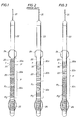
- Fig. 1 shows a preferred mode of the present invention
- Fig. 2 shows a standard prior tool
- Fig. 3 shows an alternative mode of the present invention.
- Prior to an analysis of the noise suppression design characteristics of a housing of the present invention specific examples of preferred modes are shown.
- Fig. 1 there is illustrated an elongated but rigidly constructed acoustic logging tool 20 adapted for passage through a well bore (not shown) by means of an armored electrical cable 21 and winch (not shown) which is situated at the earth's surface.
- the tool 20 includes an upper, tubular cartridge 22 and a lower, tubular housing 23 , both of which are preferably constructed of steel.
- a single centralizer support device 24 disposed at the center of gravity of the tool 20 may be employed if the tool is to be centered in a well bore. Alternatively, two or more centralized supports disposed along the length of the tool may be employed if so desired.
- a caliper device 25 for measuring the diameter of the well bore, or other similar secondary devices may be coupled to the tool 20 , for example, at its lower end as shown in the drawing.
- a coaxially disposed mandrel (not shown) supports transmitter and receiver transducers mounted thereon in a preselected fixed spaced relationship.
- the housing 23 surrounds the mandrel and the transducers mounted on the mandrel.
- the transmitter T and receivers R1 and R2 are generally mounted in a fixed spaced relationship on a rigid mandrel with the transmitter T , receivers R1 and R2 and supporting mandrel all surrounded by the protective housing 23 .
- the protective housing 23 For simplicity, one transmitter and two receivers are indicated. However acoustic tools often use multiple transmitters and receivers, and such arrays of transducers are, as such, contemplated.
- the electronic circuits of cartridge 22 are coupled via cable 21 to conventional surface indicating and recorder instruments (not shown).
- the time measuring function may be accomplished by circuits as well known in the art such as shown in U.S. Patent 3,191,141 wherein a keying circuit periodically triggers the transmitter T to emit a pulse of acoustic energy.
- the keying circuit also determines the period during which each receiver R1 and R2 are activated to receive acoustic signals. This has been used to provide first arrival time determinations. Permitting the receivers R1 and R2 to continue receiving acoustic signals after the first arrival permits sensing of full acoustic wave forms. Such received signals are transmitted up the cable 22 for recording as acoustic logs.
- the lower, tubular housing 23 includes three illustrative housing sections identified by the number 30 and differentiated from one another by the letters a, b, and c .
- Housing sections 30 a (transmitter), 30 b (intermediate) and 30 c (receiver) acoustically separate the transducers (transmitter T and receivers R1 and R2 ) from each other by the acoustic transmission response of the housing sections identified.
- the receiver housing section 30c extends above the receiver R1 and below the receiver R2 to fully extend in the entire vicinity of the receivers. More clearly described, the pattern of the receiver section extends from a longitudinal point (P or P1 ) between the transmitting area and the receiving area (such as at the beginning point of the receiving area.
- each housing section 30 is constructed and arranged to permit and to facilitate the travel of acoustic energy in a generally radial pattern between a transducer within the tubular housing and the drilling fluids or muds (not shown) in the well bore which are exterior of the transducers. Also, in general, each housing section 30 is constructed and arranged so as to increase the apparent time required for detectable energy to travel over the portions of the housing between the transducers.
- Each housing section 30 is constructed and arranged to provide void spaces about the periphery and along the length of the housing 23 which form a generally tortuous longitudinal path from transmitter to receiver.
- intermediate housing section 30 b located between the transmitter T and the receiver section 30 c may involve another acoustic delay or suppression means, as by a cable with or without additional acoustic suppression or damping means.
- the acoustic signal transmitted from the transmitter, along the cable to and along the receiver section housing is therefore defined as being for this invention simply another tortuous path between the transmitter and receivers. Therefore it simply is treated under this invention as an intermediate housing with an acoustic delay pattern.
- acoustic wave transmission lengthwise of the housing occurs by traveling tortuous paths which extend longitudinally along the housing 23 and which are greater than the straight line distance between a successive pair of points. This arrangement provides the desired acoustic delay for the housing 23 .
- the tool housing 23 is also constructed to minimize secondary acoustic noise generation in the vicinity of the receivers R1 and R2 . More specifically, as shown in Figs. 1 and 3, the receiver housing section 30 c exhibits a characteristic pattern which prevails over the entire length of the lower housing in the vicinity of or about the receivers R1 and R2 .
- a preferred pattern, shown in Fig. 1, shows a single continuous pattern extending from the transmitter T to a point past the end of the last receiver.
- This pattern on the housing sections 30 a , b and c provides both a delay in arrival time of the acoustic signal generated by transmitter T that is conveyed along the housing 23 as well as minimization of acoustic static or noise produced by the housing in the vicinity of the receivers that would distort the full acoustic waveforms.
- an intermediate housing section 30 b with an excellent acoustic delay pattern may separate the transmitter T from the receiver section 30 c , while a continuous pattern is provided on receiver housing section 30 c with an acoustically transparent or non-static forming configuration.
- prior tools as shown in Fig. 2 provide acoustic sections 30 a , 30 b and 30 c respectively about the transmitter T between the transmitter T and the receiver R1 and between the receivers R1 and R2 .
- a discontinuous open slotted pattern surrounds the receivers R1 and R2 and the transmitter T .
- the discontinuity in the pattern of the acoustic inhibiting section 30 c around the receivers R1 and R2 created by the window-slot-window pattern provides an undesirable acoustic noise signal that may be received by the receivers R1 and R2 especially during full acoustic waveform logging. More specifically, the discontinuous pattern or pattern change from the intermediate section 30b to the receiver section 30 c and the discontinuities within the receiver section 30 c produce an acoustic scattering that is received as acoustic noise in the vicinity of the receivers.
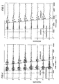
- FIG. 4 shows a section of an acoustic logging run using a prior housing of the type shown in Fig. 2.
- the logging tool having an array of eight spaced receivers was tested at a borehole depth of 3100 feet.
- the waveforms contain the expected compressional, shear and Stoneley waves.
- the shape of the Stoneley arrival varies widely from receiver to receiver. This variation is due in large part to the noise produced by the housing in the vicinity of the receivers.
- a phantom "secondary Stoneley" wave appears to be received (not shown), arriving between the compressional and Stoneley wavelets. This "secondary Stoneley" is believed to be the result of coherent scattering of the compressional wave form the discontinuous pattern of the prior tool housing.
- FIG. 5 For comparison, an array of waveforms from an eight receiver array tool having the housing of Fig. 1 at the same depth and in the same hole is shown in Fig. 5.
- the coherence of the waveform is far superior across each of the receivers in the array showing only amplitude degradation over distance as expected. Additionally, no phantom signals are developed in soft formations by the tool housing.
- the housing shown in Fig. 1 therefore substantially eliminates the noise that is produced by the prior art housing designs.
- a characteristic feature of this novel housing according to the present invention must have a receiver section having a continuous pattern.
- the preferred housings shown in Fig. 1 and 3 meet this requirement as they have receiver sections 30 c that have a single continuous pattern longitudinally about the tool.
- the prior tools (as Fig. 2) have discontinuous patterns (such as provided by the "windows" over the receivers R1 and R2 separated by a standard slotted section) in the receiver sections, thus producing secondary noise.
- Fig. 6 shows the outer surface of a portion of the housing of Fig. 1 in the vicinity of the receivers ( 30 c ) developed in the plane of the drawing. For simplicity, this is referred to as the "unwrapped" pattern of the housing of Fig. 1.
- Fig. 6 shows an interleaved or "brick work” pattern of slots (holes) cut into the wall of the housing.
- the pattern of the receiver section 30 c of the housing 23 is subject to suitable design criteria depending on the five above noted functional variables.
- the first two relate to general acoustic logging tool housings. The latter six become apparent from comparison testing. Although a housing of the present invention should maintain the first two design criteria, as will be seen, some of the latter criteria may be ignored. However, it is a requirement of the invention to have a continuous pattern in the vicinity of the receivers, with the most preferred sonde housing generally meeting all of the following design requirements:
- Figs. 7-9 show various other unwrapped patterns of receiver area housing sections, although other patterns including continuous patterns of circles, ovals and other repeated patterns of holes cut out or otherwise embossed into the housing are contemplated. Modern metalworking and cutting techniques, including the use of high energy cutting lasers has permitted the cutting of holes in the metal housings to provide almost any pattern of holes.
- Fig. 7 shows a preferred pattern, specifically a double-helix diamond pattern, as shown about the receivers R1 and R2 in Fig. 3, which may be cut by a laser. As previously noted, this diamond pattern may extend over any portion, including the entirety, of the housing 23 so long as the pattern extends continuously over the housing in the vicinity of the receivers.
- the double-helix diamond pattern is so named due to the formation of two opposing sets of three helixes on the tube axis, shown by lines h1 through h6. Such helixes form a set of interleaved holes in the housing. Specific physical measurements for a housing laser cut from 3.625 O.D. X 3.03 I.D.
- the axial uniformity of the helix pattern minimizes acoustic reflections along the housing, helping to maximize acoustic waveform coherence.
- the 3.0 inch axial period causes waveform frequency distortion to occur at twice the frequency of prior housings having the usual 6.0 inch periods.
- the absence of periodic ring like elements (found in both the Figs. 1 and 2 housings and noted at "c” in Figs. 6, 8, and 9) reduces waveform distortion caused by the resonant vibration (ringing) of such elements.
- the high average openness (less metal coverage) over the receiver array is beneficial because borehole modes are suppressed and attenuated; i.e. providing better transmission from the borehole of acoustic signals.
- FIG. 8 Another configuration of the housing can be seen in Fig. 8.
- This pattern is referred to as the "minimum metal” pattern as it has a very high average openness and reduces therefore the amount of metal in the sleeve between the formation and the receivers. Additionally, as the holes are linearly patterned, not interleaved, no acoustically delaying tortuous paths are created. Proper sizing of the holes or slots, however, according to the remaining design parameters provides an excellent housing for acoustical tools.
- FIG. 9 An optional minimum metal pattern is shown in Fig. 9. The difference in pattern being in the size of the holes along the circumferential alternating wide and narrow holes. Larger holes being useful, for example,, to provide a greater openness about the receivers.Nearly any ratio of widths for large to narrow holes may be used subject to the noted design criteria. Thusly various sized holes can be placed in the pattern (there is no requirement that all holes or metal remaining be of a single size) as long as the pattern is longitudinally continuous in the vicinity of the receivers.
- any particular housing may not follow all of the noted design criteria.
- Table Design Criteria Rectangular (Fig. 6) Diamond (Fig. 7) Minimum Metal (Fig. 8 & 9) 1. Slowness: Yes Acceptable No 2. Structural Strength: Yes Yes Yes 3. Periodicity (1/2A min ) for scattering: Yes Acceptable Yes 4. Periodicity (A min ) for Powder: Yes Yes Yes 5. Open as much as possible: Acceptable Yes Yes 6. Periodicity ( «A min ) for Stoneley mode coupling: Yes Yes Yes 7.
Landscapes
- Physics & Mathematics (AREA)
- Life Sciences & Earth Sciences (AREA)
- Engineering & Computer Science (AREA)
- Acoustics & Sound (AREA)
- Environmental & Geological Engineering (AREA)
- Geology (AREA)
- Remote Sensing (AREA)
- General Life Sciences & Earth Sciences (AREA)
- General Physics & Mathematics (AREA)
- Geophysics (AREA)
- Geophysics And Detection Of Objects (AREA)
- Artificial Fish Reefs (AREA)
Applications Claiming Priority (2)
| Application Number | Priority Date | Filing Date | Title |
|---|---|---|---|
| US07/122,978 US4850450A (en) | 1987-11-19 | 1987-11-19 | Logging tool housing with acoustic delay |
| US122978 | 2002-04-15 |
Publications (3)
| Publication Number | Publication Date |
|---|---|
| EP0317386A2 true EP0317386A2 (de) | 1989-05-24 |
| EP0317386A3 EP0317386A3 (en) | 1990-05-16 |
| EP0317386B1 EP0317386B1 (de) | 1993-01-13 |
Family
ID=22406019
Family Applications (1)
| Application Number | Title | Priority Date | Filing Date |
|---|---|---|---|
| EP88402704A Expired - Lifetime EP0317386B1 (de) | 1987-11-19 | 1988-10-27 | Gehäuse für ein Bohrlochmessgerät mit akustischer Verzögerung |
Country Status (6)
| Country | Link |
|---|---|
| US (1) | US4850450A (de) |
| EP (1) | EP0317386B1 (de) |
| BR (1) | BR8806060A (de) |
| DE (1) | DE3877532D1 (de) |
| NO (1) | NO173473C (de) |
| OA (1) | OA08929A (de) |
Cited By (7)
| Publication number | Priority date | Publication date | Assignee | Title |
|---|---|---|---|---|
| FR2698967A1 (fr) * | 1992-12-04 | 1994-06-10 | Inst Francais Du Petrole | Outil de diagraphie à balayage circulaire. |
| WO2000017673A3 (en) * | 1998-09-24 | 2000-09-21 | Dresser Ind | Method and apparatus for absorbing acoustic energy |
| US6213250B1 (en) | 1998-09-25 | 2001-04-10 | Dresser Industries, Inc. | Transducer for acoustic logging |
| EP0900918A3 (de) * | 1997-08-09 | 2001-09-12 | Anadrill International SA | Verfahren und Anordnung zur Unterdrukkung von Schwingungen einer Bohrgestänge |
| US6366531B1 (en) | 1998-09-22 | 2002-04-02 | Dresser Industries, Inc. | Method and apparatus for acoustic logging |
| US6693554B2 (en) | 1999-02-19 | 2004-02-17 | Halliburton Energy Services, Inc. | Casing mounted sensors, actuators and generators |
| CN104712324A (zh) * | 2014-12-11 | 2015-06-17 | 杭州丰禾石油科技有限公司 | 用于声波测井仪的新型隔声体测井装置及最优化设计方法 |
Families Citing this family (27)
| Publication number | Priority date | Publication date | Assignee | Title |
|---|---|---|---|---|
| US5852587A (en) * | 1988-12-22 | 1998-12-22 | Schlumberger Technology Corporation | Method of and apparatus for sonic logging while drilling a borehole traversing an earth formation |
| US5796677A (en) * | 1988-12-22 | 1998-08-18 | Schlumberger Technology Corporation | Method of sonic logging while drilling a borehole traversing an earth formation |
| US5687138A (en) * | 1995-10-03 | 1997-11-11 | Schlumberger Technology Corporation | Methods of analyzing stoneley waveforms and characterizing underground formations |
| US5753812A (en) * | 1995-12-07 | 1998-05-19 | Schlumberger Technology Corporation | Transducer for sonic logging-while-drilling |
| US6135234A (en) * | 1997-01-02 | 2000-10-24 | Gas Research Institute | Dual mode multiple-element resonant cavity piezoceramic borehole energy source |
| US5838633A (en) * | 1997-01-27 | 1998-11-17 | Schlumberger Technology Corporation | Method for estimating formation in-situ stress magnitudes using a sonic borehole tool |
| GB2352295B (en) * | 1998-04-28 | 2002-12-24 | Schlumberger Ltd | Acoustic logging tool |
| US6988566B2 (en) * | 2002-02-19 | 2006-01-24 | Cdx Gas, Llc | Acoustic position measurement system for well bore formation |
| US6615949B1 (en) * | 1999-06-03 | 2003-09-09 | Baker Hughes Incorporated | Acoustic isolator for downhole applications |
| MXPA03003723A (es) | 2000-11-16 | 2003-07-28 | Schlumberger Technology Bv | Herramienta de sondeo sonica que incluye una estructura de separacion y recepcion. |
| US6800987B2 (en) * | 2002-01-22 | 2004-10-05 | Measurement Specialties, Inc. | Protective housing for ultrasonic transducer apparatus |
| US6588267B1 (en) * | 2002-03-12 | 2003-07-08 | Titan Specialties, Ltd. | Isolator bar for acoustic instruments used in downhole formations |
| US7334661B2 (en) * | 2004-02-05 | 2008-02-26 | Schlumberger Technology Corporation | Acoustic logging tool sleeve |
| USD568123S1 (en) * | 2004-06-30 | 2008-05-06 | Bantle Kevin E | Logging tool |
| DE102006035038A1 (de) * | 2006-07-28 | 2008-01-31 | Epcos Ag | Federelement sowie Piezoaktor mit dem Federelement |
| US9080425B2 (en) * | 2008-10-17 | 2015-07-14 | Foro Energy, Inc. | High power laser photo-conversion assemblies, apparatuses and methods of use |
| US9557435B2 (en) * | 2012-12-20 | 2017-01-31 | Schlumberger Technology Corporation | Acoustic isolators |
| US9453405B2 (en) * | 2013-02-25 | 2016-09-27 | Fmc Technologies, Inc. | Noise isolation tool |
| RU2530435C1 (ru) * | 2013-04-09 | 2014-10-10 | Российская Федерация, от имени которой выступает Государственная корпорация по атомной энергии "Росатом" | Устройство защиты первичного преобразователя ускорения |
| AU2013403956A1 (en) * | 2013-10-31 | 2016-03-10 | Halliburton Energy Services, Inc. | Acoustic signal attenuator for LWD/MWD logging systems |
| WO2016022826A1 (en) | 2014-08-08 | 2016-02-11 | Halliburton Energy Services, Inc. | Structural element for sonic tools and acoustic isolators |
| FR3026569B1 (fr) * | 2014-09-26 | 2017-12-08 | Thales Sa | Antenne omnidirectionnelle |
| CN105275451B (zh) * | 2015-09-25 | 2019-05-07 | 武汉力博物探有限公司 | 一种钻孔径向三维成像系统 |
| US11513249B2 (en) | 2019-10-11 | 2022-11-29 | Scientific Drilling International, Inc. | Downhole acoustic device |
| US11506809B2 (en) | 2020-05-29 | 2022-11-22 | Saudi Arabian Oil Company | System and method for acoustically imaging wellbore during drilling |
| US11434747B2 (en) | 2020-07-24 | 2022-09-06 | Baker Hughes Oilfield Operations Llc | Down-hole tools comprising layers of materials and related methods |
| US11512586B2 (en) | 2020-10-06 | 2022-11-29 | Halliburton Energy Services, Inc. | Logging while drilling tool |
Family Cites Families (7)
| Publication number | Priority date | Publication date | Assignee | Title |
|---|---|---|---|---|
| US3191142A (en) * | 1961-05-16 | 1965-06-22 | Schlumberger Well Surv Corp | Low acoustic velocity support member for logging tools |
| US3191143A (en) * | 1961-05-16 | 1965-06-22 | Schlumberger Well Surv Corp | Acoustic delay member for well logging tools |
| US3191141A (en) * | 1961-05-16 | 1965-06-22 | Schlumberger Well Surv Corp | Logging tool housing with acoustic delay |
| US3191144A (en) * | 1961-08-08 | 1965-06-22 | Schlumberger Well Surv Corp | Stand off apparatus for logging tool |
| FR1349958A (fr) * | 1962-10-26 | 1964-01-24 | Schlumberger Well Surv Corp | Appareil pour l'exploration des sondages, notamment par procédés acoustiques |
| US3271733A (en) * | 1964-07-08 | 1966-09-06 | Schlumberger Well Surv Corp | Acoustic well logging device |
| US4020452A (en) * | 1971-05-24 | 1977-04-26 | Schlumberger Technology Corporation | Apparatus for use in investigating earth formations |
-
1987
- 1987-11-19 US US07/122,978 patent/US4850450A/en not_active Expired - Lifetime
-
1988
- 1988-10-27 EP EP88402704A patent/EP0317386B1/de not_active Expired - Lifetime
- 1988-10-27 DE DE8888402704T patent/DE3877532D1/de not_active Expired - Lifetime
- 1988-10-31 NO NO884839A patent/NO173473C/no unknown
- 1988-11-18 BR BR888806060A patent/BR8806060A/pt not_active IP Right Cessation
- 1988-11-18 OA OA59476A patent/OA08929A/xx unknown
Cited By (16)
| Publication number | Priority date | Publication date | Assignee | Title |
|---|---|---|---|---|
| FR2698967A1 (fr) * | 1992-12-04 | 1994-06-10 | Inst Francais Du Petrole | Outil de diagraphie à balayage circulaire. |
| EP0900918A3 (de) * | 1997-08-09 | 2001-09-12 | Anadrill International SA | Verfahren und Anordnung zur Unterdrukkung von Schwingungen einer Bohrgestänge |
| US6535458B2 (en) | 1997-08-09 | 2003-03-18 | Schlumberger Technology Corporation | Method and apparatus for suppressing drillstring vibrations |
| US6366531B1 (en) | 1998-09-22 | 2002-04-02 | Dresser Industries, Inc. | Method and apparatus for acoustic logging |
| US6552962B1 (en) | 1998-09-22 | 2003-04-22 | Dresser Industries, Inc. | Method and apparatus for acoustic logging |
| WO2000017673A3 (en) * | 1998-09-24 | 2000-09-21 | Dresser Ind | Method and apparatus for absorbing acoustic energy |
| US6564899B1 (en) | 1998-09-24 | 2003-05-20 | Dresser Industries, Inc. | Method and apparatus for absorbing acoustic energy |
| US6213250B1 (en) | 1998-09-25 | 2001-04-10 | Dresser Industries, Inc. | Transducer for acoustic logging |
| US6693554B2 (en) | 1999-02-19 | 2004-02-17 | Halliburton Energy Services, Inc. | Casing mounted sensors, actuators and generators |
| US6747570B2 (en) | 1999-02-19 | 2004-06-08 | Halliburton Energy Services, Inc. | Method for preventing fracturing of a formation proximal to a casing shoe of well bore during drilling operations |
| US6987463B2 (en) | 1999-02-19 | 2006-01-17 | Halliburton Energy Services, Inc. | Method for collecting geological data from a well bore using casing mounted sensors |
| US7046165B2 (en) | 1999-02-19 | 2006-05-16 | Halliburton Energy Services, Inc. | Method for collecting geological data ahead of a drill bit |
| US7173542B2 (en) | 1999-02-19 | 2007-02-06 | Halliburton Energy Services, Inc. | Data relay for casing mounted sensors, actuators and generators |
| US7932834B2 (en) | 1999-02-19 | 2011-04-26 | Halliburton Energy Services. Inc. | Data relay system for instrument and controller attached to a drill string |
| CN104712324A (zh) * | 2014-12-11 | 2015-06-17 | 杭州丰禾石油科技有限公司 | 用于声波测井仪的新型隔声体测井装置及最优化设计方法 |
| CN104712324B (zh) * | 2014-12-11 | 2018-01-19 | 杭州丰禾石油科技有限公司 | 用于声波测井仪的新型隔声体测井装置及最优化设计方法 |
Also Published As
| Publication number | Publication date |
|---|---|
| EP0317386A3 (en) | 1990-05-16 |
| EP0317386B1 (de) | 1993-01-13 |
| NO884839D0 (no) | 1988-10-31 |
| NO173473C (no) | 1993-12-15 |
| BR8806060A (pt) | 1989-08-08 |
| US4850450A (en) | 1989-07-25 |
| NO884839L (no) | 1989-05-22 |
| OA08929A (en) | 1989-10-31 |
| NO173473B (no) | 1993-09-06 |
| DE3877532D1 (de) | 1993-02-25 |
Similar Documents
| Publication | Publication Date | Title |
|---|---|---|
| EP0317386B1 (de) | Gehäuse für ein Bohrlochmessgerät mit akustischer Verzögerung | |
| US5852587A (en) | Method of and apparatus for sonic logging while drilling a borehole traversing an earth formation | |
| US4649525A (en) | Shear wave acoustic logging system | |
| AU721408B2 (en) | Transducer for sonic logging-while-drilling | |
| US4571693A (en) | Acoustic device for measuring fluid properties | |
| US7032707B2 (en) | Acoustic isolator downhole applications | |
| US4641724A (en) | Fracture detection using circumferential offset acoustic paths | |
| US5796677A (en) | Method of sonic logging while drilling a borehole traversing an earth formation | |
| US3376950A (en) | Acoustical well logging methods and apparatus for determining the dip and other characteristics of earth formations traversed by a borehole | |
| CA1152201A (en) | Shear wave acoustic logging system | |
| US3191141A (en) | Logging tool housing with acoustic delay | |
| US6915875B2 (en) | Acoustic isolator for downhole applications | |
| EP0375549B1 (de) | Verfahren und Vorrichtung zur Durchführung akustischer Untersuchungen in einem Bohrloch | |
| US7028806B2 (en) | Acoustic isolator for downhole applications | |
| US3363719A (en) | Acoustic velocity logging method and apparatus having lateral and longitudinal receiovers | |
| US6739423B2 (en) | Acoustic logging tool | |
| US6494288B1 (en) | Acoustic logging tool | |
| US20090242317A1 (en) | Expandable downhole tool | |
| US3191142A (en) | Low acoustic velocity support member for logging tools | |
| EP0717272B1 (de) | Verfahren zum Feststellen der Laufzeitsgeschwindigkeit von Ultraschallwellen durch Steinfragmente | |
| GB2308190A (en) | Acoustic reflection borehole logging apparatus | |
| US9329294B2 (en) | Sonic borehole caliper and related methods | |
| CA1249050A (en) | Acoustic device for measuring rock permeability | |
| CA3247801C (en) | Near field ultrasonic logging | |
| Stripling | Velocity Log Characteristics |
Legal Events
| Date | Code | Title | Description |
|---|---|---|---|
| PUAI | Public reference made under article 153(3) epc to a published international application that has entered the european phase |
Free format text: ORIGINAL CODE: 0009012 |
|
| AK | Designated contracting states |
Kind code of ref document: A2 Designated state(s): DE FR GB IT NL |
|
| PUAL | Search report despatched |
Free format text: ORIGINAL CODE: 0009013 |
|
| AK | Designated contracting states |
Kind code of ref document: A3 Designated state(s): DE FR GB IT NL |
|
| 17P | Request for examination filed |
Effective date: 19901019 |
|
| 17Q | First examination report despatched |
Effective date: 19910917 |
|
| GRAA | (expected) grant |
Free format text: ORIGINAL CODE: 0009210 |
|
| AK | Designated contracting states |
Kind code of ref document: B1 Designated state(s): DE FR GB IT NL |
|
| PG25 | Lapsed in a contracting state [announced via postgrant information from national office to epo] |
Ref country code: IT Free format text: LAPSE BECAUSE OF FAILURE TO SUBMIT A TRANSLATION OF THE DESCRIPTION OR TO PAY THE FEE WITHIN THE PRE;WARNING: LAPSES OF ITALIAN PATENTS WITH EFFECTIVE DATE BEFORE 2007 MAY HAVE OCCURRED AT ANY TIME BEFORE 2007. THE CORRECT EFFECTIVE DATE MAY BE DIFFERENT FROM THE ONE RECORDED.SCRIBED TIME-LIMIT Effective date: 19930113 Ref country code: NL Effective date: 19930113 Ref country code: DE Effective date: 19930113 |
|
| REF | Corresponds to: |
Ref document number: 3877532 Country of ref document: DE Date of ref document: 19930225 |
|
| ET | Fr: translation filed | ||
| NLV1 | Nl: lapsed or annulled due to failure to fulfill the requirements of art. 29p and 29m of the patents act | ||
| PLBE | No opposition filed within time limit |
Free format text: ORIGINAL CODE: 0009261 |
|
| STAA | Information on the status of an ep patent application or granted ep patent |
Free format text: STATUS: NO OPPOSITION FILED WITHIN TIME LIMIT |
|
| 26N | No opposition filed | ||
| PGFP | Annual fee paid to national office [announced via postgrant information from national office to epo] |
Ref country code: FR Payment date: 19961021 Year of fee payment: 9 |
|
| PG25 | Lapsed in a contracting state [announced via postgrant information from national office to epo] |
Ref country code: FR Free format text: THE PATENT HAS BEEN ANNULLED BY A DECISION OF A NATIONAL AUTHORITY Effective date: 19971031 |
|
| REG | Reference to a national code |
Ref country code: FR Ref legal event code: ST |
|
| REG | Reference to a national code |
Ref country code: GB Ref legal event code: IF02 |
|
| PGFP | Annual fee paid to national office [announced via postgrant information from national office to epo] |
Ref country code: GB Payment date: 20051026 Year of fee payment: 18 |
|
| GBPC | Gb: european patent ceased through non-payment of renewal fee |
Effective date: 20061027 |
|
| PG25 | Lapsed in a contracting state [announced via postgrant information from national office to epo] |
Ref country code: GB Free format text: LAPSE BECAUSE OF NON-PAYMENT OF DUE FEES Effective date: 20061027 |